mru 500GD User manual

HC40X
RM400
HM400
IR400
RF400
CO400
CD400
500GD
USER MANUAL
6822EN

User manual 500GD
2 / 52 MRU GmbH, D-74172 Neckarsulm
Manufacturer:
Legal notices / Intellectual property rights comments
Original user manual
© 2022 by MRU
No part of this manual may be published in any form (print, photocopy, electronic
media or any other publication form) without a written approval by the publisher.
All user trademarks and name mark descriptions, even those which are not marked as
such, are properties of the respective owners.
Edition: 2022-02-23, V1.01.EN

User manual 500GD
MRU GmbH, D-74172 Neckarsulm 3 / 52
Table of content
1Information for product and safety .............................................. 6
1.1. Safety manual .................................................................................................6
1.2. Safety precautions.........................................................................................6
2Introduction...................................................................................... 7
2.1. Intended use ...................................................................................................7
2.2. About us ...........................................................................................................8
3Description...................................................................................... 10
3.1. Purpose .......................................................................................................... 10
3.2. The Analyser................................................................................................. 11
3.3. User interface............................................................................................... 12
3.4.
Menu structure
......................................................................................... 13
4Operation ........................................................................................ 14
4.1. Commissioning............................................................................................ 14
4.2. Charging the battery................................................................................. 14
4.3. Switching on the analyser ....................................................................... 14
4.4. Make settings on the basic unit............................................................ 15
Setting options for QR code .......................................................................... 15
Setting language ................................................................................................ 16
Setting brightness.............................................................................................. 16
Setting volume.................................................................................................... 17
Setting Off time .................................................................................................. 17
4.5. Switching off the analyser ......................................................................... 18
5Measuring ....................................................................................... 19
5.1. Inserting interchangeable sensor ......................................................... 19
Use interchangeable sensor without probe tube................................... 19
Use interchangeable sensor with probe tube.......................................... 20
Set alarm mode................................................................................................... 20
5.2. Detection with interchangeable sensor HC40X............................... 21
Starting detection .............................................................................................. 21
Configuring detection ...................................................................................... 23
Setting Zeropoint............................................................................................... 23
Selecting gas........................................................................................................ 23
Setting alarm threshold ................................................................................... 24
Setting unit........................................................................................................... 24
5.3. Measuring with interchangeable sensor RM400 ............................ 25
Starting measurement...................................................................................... 25
Configuring measurement.............................................................................. 26
User manual 500GD
4 / 52 MRU GmbH, D-74172 Neckarsulm
Setting Zeropoint ...............................................................................................26
5.4. Measuring with interchangeable sensor HM400............................26
Starting measurement......................................................................................27
Configuring measurement..............................................................................27
Selecting measured values..............................................................................27
Setting unit ...........................................................................................................28
5.5. Measuring with interchangeable sensor IR400 ...............................29
Starting measurement......................................................................................29
Configuring measurement..............................................................................30
Setting emissivity................................................................................................30
Setting alarm threshold.................................................................................... 31
Setting unit ...........................................................................................................31
5.6. Detection with interchangeable sensor RF400 ................................32
Starting detection............................................................................................... 32
Configuring detection....................................................................................... 33
Setting Zeropoint ...............................................................................................33
Selecting refrigerant..........................................................................................33
Setting alarm threshold....................................................................................34
5.7. Measuring with interchangeable sensor CO400 .............................35
Starting measurement......................................................................................35
Configuring measurement..............................................................................35
Setting Zeropoint ...............................................................................................36
Setting alarm threshold....................................................................................36
Setting unit ...........................................................................................................37
5.8. Measuring with interchangeable sensor CD400 .............................38
Starting measurement......................................................................................38
Configuring measurement..............................................................................38
Setting Zeropoint ...............................................................................................39
Setting alarm threshold....................................................................................39
5.9. Exporting the measurement protocol via QR code........................40
6Display device information ...........................................................41
6.1. Display device information of the basic unit....................................41
6.2. Display sensor information .....................................................................41
7Maintenance and care....................................................................42
7.1. Maintenance.................................................................................................42
7.2. Care..................................................................................................................42
7.3. Sensor-specific care instructions ..........................................................42

User manual 500GD
MRU GmbH, D-74172 Neckarsulm 5 / 52
8Appendix ......................................................................................... 43
8.1. Technical data 500 GD.............................................................................. 43
8.2. Interchangeable Sensors ......................................................................... 44
Interchangeable Sensor HC400 (Nr.11138) .............................................. 44
Interchangeable Sensor HC401 (Nr.11591) .............................................. 44
Interchangeable Sensor HC402 (Nr.11733) .............................................. 45
Interchangeable Sensor RM400 (Nr.11191).............................................. 46
Interchangeable Sensor IR400 (Nr.12121) ................................................ 46
Interchangeable Sensor HM400 (Nr.11922)............................................. 47
Interchangeable Sensor RF400 (Nr.11900) ............................................... 48
Interchangeable sensor CO400 (Nr.12130)............................................... 49
Interchangeable sensor CD400 (Nr.12623)............................................... 49
8.3. Service menu................................................................................................ 50
9Declaration of conformity............................................................. 51

User manual 500GD
6 / 52 MRU GmbH, D-74172 Neckarsulm
1Information for product and safety
1.1. Safety manual
All general information and safety precautions of MRU products are
listed in the supplied separate safety manual.
Therefore, this manual must be read and observed before the first use
of the analyser.
All information and safety precautions for the analyser 400GD in the
Safety Manual also apply to the analyser 500GD.
Instrument-specific safety and warning requirements in this manual are
prefixed before dangerous actions.
1.2. Safety precautions
The used categories of safety precautions are here explained once
more.
DANGER
Identifies an immediate, impending hazard that, if
ignored, will result in severe bodily injuries or death.
WARNING
Identifies an immediate, impending hazard that, if
ignored, may result in severe bodily injuries, material
damage or death.
CAUTION
Identifies a possibly dangerous situation that, if
ignored, may result in minor injuries.
ATTENTION
Identifies a possibly harmful situation that, if ignored,
may result in damages to the device or its
surroundings.
NOTE
Identifies user tips and other especially important infor-
mation.
The explanation of safety notices:
CAUTION
HOT –danger of burns and fire hazards from gas
extraction probe.
Physical harm and property damage can be caused.
►Cool down the probe tube.

User manual 500GD
MRU GmbH, D-74172 Neckarsulm 7 / 52
2Introduction
•Read and observe the safety manual supplied separately.
•This user manual enables you to operate the analyser safely.
•Read this user manual carefully.
•Make yourself familiar with the analyser, before using it.
•The analyser may only be used by skilled personnel and may only be
used for its intended purpose.
•Pay special attention to the security and warning precautions, in
order to prevent injuries and product damages.
•MRU can’t be held responsible for damages or injuries, by not
following the instructions in this manual.
•Always keep this user manual near you, when working with the
analyser, to be able to read instructions as needed.
•Ensure to hand over all documents to when handing the analyser
over to other.
2.1. Intended use
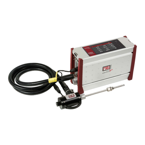
The analyser is a multidetector. Due to interchangeable sensors, the
analyser can be used for a wide range of applications:
•Usable with interchangeable sensor RM400 for leak detection on ex-
haust pipes.
•Usable with interchangeable sensor HC400, HC401 and HC402 for
leak detection on gas lines in non-explosive environments.
•Usable with interchangeable sensor RF400 for leak detection on
refrigeration systems.
•Usable with interchangeable sensor HM400 to measure environmen-
tal parameters (air pressure, humidity, air temperature and dew
point).
•Usable with interchangeable sensor CO400 for monitoring the CO-
concentration in the ambient air.
•Usable with interchangeable sensor CD400 for monitoring the CO2-
concentration in the ambient air.
Note that all interchangeable sensors are developed for indoor use only.
►Do not use the interchangeable sensors outdoor.
The analyser records and stores measured values. The measured
values can be exported by QR code.
The analyser was manufactured according to relevant standards and
regulations. The analyser must be used according to the instructions
for the intended used.

User manual 500GD
8 / 52 MRU GmbH, D-74172 Neckarsulm
WARNING
Risk from manipulations to the measuring device
Operational safety hazard
Modifications or changes to the measuring device
are not allowed.
2.2. About us
The analyser is produced by the MRU GmbH in Neckarsulm, Germany
(Founded in 1984), a medium sized company that specializes in devel-
oping, producing and marketing high quality emission monitoring
analysers.
MRU GmbH produces a wide range of instruments, from standard
analysers up to tailor made industrial analysers.
Plant 1: Sales, Service, R&D
Plant 2: Production

User manual 500GD
MRU GmbH, D-74172 Neckarsulm 9 / 52
MRU GmbH
Fuchshalde 8 + 12
74172 Neckarsulm - Obereisesheim
GERMANY
Tel +49 71 32 99 62 0 (Front office)
Tel +49 71 32 99 62 61 (Service)
Fax +49 71 32 99 62 20
Email: [email protected]
Site: www.mru.eu

User manual 500GD
10 / 52 MRU GmbH, D-74172 Neckarsulm
3Description
3.1. Purpose
The main purpose of the analyser in combination with various inter-
changeable sensors is the detection of gases and exhaust gases in gas
and heating installations.
For example, checking of:
•freely laid gas pipelines
•ambient air for combustible gases
•manholes and cavities
•Installations for external tightness
•newly laid gas pipelines for leaks.
In addition, the range of application of the analyser can be extended by
further interchangeable sensors.
The following interchangeable sensors are available:
•Gas sensor H40x for detecting leaks in gas pipes.
•Humidity sensor RM400 for detecting leaks in flue pipes.
•Condensing humidity sensor RM400 for spillage tests on flue gas
•Systems
•Infrared temperature sensor IR400 for contactless measurement of
surface temperature
•Hygrometer sensor HM400 for the check of indoor climate.
•Refrigerant detector RF400 for leak detection on refrigeration
Systems
•Gas sensor CO400 for monitoring the CO-concentration in the
ambient air.
Visit our webpage www.mru.eu to see available options or talk to your
MRU representative.

User manual 500GD
MRU GmbH, D-74172 Neckarsulm 11 / 52
3.2. The Analyser
The analyser consists of a compact and robust glass-fibre reinforced
plastic housing.
No.
Description
No.
Description
1
Unscrewable filter grid
2
Flexible arm
3
Interchangeable Sensor
4
Sensor connector
5
Display
6
Keypad
7
Mini USB interface

User manual 500GD
12 / 52 MRU GmbH, D-74172 Neckarsulm
3.3. User interface
All functions are selected from the analyser display.
Operation and navigation are carried out via a keypad.
In the individual menus and windows additional submenus are available.
Keypad Start screen Measurement

User manual 500GD
MRU GmbH, D-74172 Neckarsulm 13 / 52
3.4.
Menu structure
All functions are available in the menu EXTRAS. The menu structure is
dynamic. The menu structure changes depending on the inserted
interchangeable sensor.
Without inserted interchangeable sensor the menu structure of the
basic unit contains the following basic menu items:
Menu item
Explanation
Start
Start a measurement
Off
Switching off Analyzer
Settings
Setting QR-code
Setting language
Setting brightness
Setting volume
Setting Off time
Service
Status vales (Battery, USB
...)
Info
Information about the
analyser
Sensor-specific menu items are explained in the corresponding
explanation of the respective interchangeable sensor.

User manual 500GD
14 / 52 MRU GmbH, D-74172 Neckarsulm
4Operation
4.1. Commissioning
The analyser leaves the factory assembled. The analyser has been
calibrated and is ready for use.
►Check the analyser for completeness and integrity.
►Charge the internal battery for at least 8 hours.
4.2. Charging the battery
The analyser has an integrated rechargeable battery.
The battery can be charged as follows:
With optional mains plug via the USB socket.
With a USB cable on the PC via the USB socket
The battery symbol displays the capacity
of the battery. The indicator changes its
colour from green to orange to red.
4.3. Switching on the analyser
Press and hold the OK key for at least 3 seconds.
The MRU start screen appears.
A display for inserting an interchangeable sensor
appears.
NOTE
If you switch on the analyser for the first time,
a screen for setting the language appears.
►Choose the desired language.
►Press “OK”.

User manual 500GD
MRU GmbH, D-74172 Neckarsulm 15 / 52
Insert an interchangeable sensor.
If necessary, a warm-up countdown appears (e. g. with HC400)
The measurement menu is being displayed after warmup.
The analyser is ready to measure.
4.4. Make settings on the basic unit
The menu structure is dynamic. The menu structure changes depending
on the inserted interchangeable sensor. In the following, only settings
are shown that can be carried out on the basic unit without am inserted
interchangeable sensor. The settings shown here can also be made with
an inserted interchangeable sensor.
Sensor-specific menu items are explained in the corresponding
explanation of the respective interchangeable sensor.
►Switch on the analyser.
The analyser indicates that an interchangeable sensor is missing.
►Press "OK".
►Choose "Settings".
A selection list appears.
►Choose the desired setting.
Setting options for QR code
The analyser uses the QR code to transmit a simple "measurement pro-
tocol".
The analyser supports QR code from firmware version V1.00.20.
If an older firmware version is installed, the firmware can be updated.
The following options are available:
•Text mode:
the protocol is transmitted in the form of a text module that can be
pasted or saved in a document.
•E-mail mode:
the protocol is transmitted in the form of a text module. The text

User manual 500GD
16 / 52 MRU GmbH, D-74172 Neckarsulm
module is marked as an email, so a smartphone/PC automatically
makes an e-mail draft.
•Off:
The measurement is not protocolled.
►Choose "QR Code".
►Press "OK".
►Choose the desired option.
►Press “OK”.
The option is saved.
Setting language
►Choose “Language”.
►Press “OK”.
►Choose the desired option.
►Press “OK”.
The desired language is saved.
Setting brightness

User manual 500GD
MRU GmbH, D-74172 Neckarsulm 17 / 52
►Choose “Display”.
►Press “OK”.
►Select the desired brightness level.
The desired brightness level is saved.
Setting volume
►Choose “Volume”.
►Press “OK”.
►Select the desired volume level.
The desired volume is saved.
Setting Off time
►Choose “Off time”.
►Press ”OK”.
►Select the desired time period.
The desired time period is saved.
If no input command is received within the desired time period,
the analyser switches off automatically.
10 seconds before the desired time period expires, a countdown
appears in the display.
Press a button before the countdown expires.
The analyser remains switched on.

User manual 500GD
18 / 52 MRU GmbH, D-74172 Neckarsulm
4.5. Switching off the analyser
There are two possibilities to switch off the analyser.
►Select „Off“.
►Press „OK“.
The analyser switches off.
Alternatively, you can switch off the analyser as follows:
►Press and hold the OK key for at least 3 seconds.
The analyser switches off.

User manual 500GD
MRU GmbH, D-74172 Neckarsulm 19 / 52
5Measuring
DANGER
Danger when used improperly
Deadly accidents can be the result if the rules are not
obeyed.
The analyzer may only be used for its intended
purpose.
DANGER
Explosion danger in EX zones
There is a possibility of explosion in an EX-zone.
The analyzer may only be used in explosion free
zones.
5.1. Inserting interchangeable sensor
Please note that there are two different ways of plugging in the inter-
changeable sensors. Some interchangeable sensors do not require a
screwed-on probe tube. The analyser automatically detects whether a
probe tube needs to be screwed on. The analyser will display a
corresponding message.
Use interchangeable sensor without probe tube
►Insert the desired interchangeable sensor into the sensor con-
nector.
►Make sure that the interchangeable sensor clicks into place audibly.
►Switch on the analyser.
See also Chapter 4.3 Switching on the analyser, Page 14.
The analyser automatically identifies the inserted
interchangeable sensor.
An information window appears in the display for approx. 5
seconds.
Depending on the interchangeable sensor, a warm-up phase
appears.

User manual 500GD
20 / 52 MRU GmbH, D-74172 Neckarsulm
Use interchangeable sensor with probe tube
►Insert the desired interchangeable sensor into the
sensor connector.
►Make sure that the interchangeable sensor clicks into place audibly.
►Switch on the analyser.
See also Chapter 4.3 Switching on the analyser, Page 14.
The analyser automatically identifies the inserted
interchangeable sensor.
An information window appears in the display for approx. 5
Seconds.
A message “Attach the probe tube” appears.
Depending on the interchangeable sensor, a warm-up phase
appears.
An animation for attaching the probe tube appears.
►Screw the probe tube onto the base unit.
A fan symbol appears in the display.
Set alarm mode
The analyser can indicate an exceeding of the set alarm thresholds by
an acoustic signal as well as by vibration
You can set how the analyser should react when the set alarm thresh-
old is exceeded.
NOTE
Note that a interchangeable sensor must be plugged in
to set the alarm mode.
Note that the setting of the alarm mode is carried out in
the measurement window.
Table of contents
Other mru Measuring Instrument manuals

mru
mru SWG100 CEM User manual

mru
mru DM 9600 CHP User manual

mru
mru NOVAplus User manual

mru
mru OPTIMA7 biogas User manual

mru
mru OPTIMA 7 BIOGAS User manual

mru
mru AIR fair SWG 100 biogas User manual

mru
mru NOVAplus BIOGAS User manual

mru
mru AMPRO 2000 GOLD User manual

mru
mru VARIOluxx User manual

mru
mru AirFair OPTIMA 7 NDIR User manual