mru SWG 100 User manual

MRU GmbH SWG 100 User Manual
Page 1of143

MRU GmbH SWG 100 User Manual
Page 2of143

MRU GmbH SWG 100 User Manual
Page 3of143
Content
1. General Information.......................................................................................................... 7
1.1. Weather and environmental conditions..................................................................7
1.2. Installation instructions..................................................................................................7
1.3. General important instructions for theplant operator.......................................7
1.4. ..............................8
1.5. General warning................................................................................................................8
1.6. Safety Information............................................................................................................9
1.7. Packing..............................................................................................................................11
1.8. Return of hazardouswaste.........................................................................................11
1.9. Return of analyzer..........................................................................................................11
1.10. MRU guarantee conditions........................................................................................12
2. Analyzer Description...................................................................................................... 13
2.1. Intendeduse....................................................................................................................13
2.1. Position of thegas in andoutlets ............................................................................13
2.2. Principleof operation...................................................................................................15
2.3. Marking and range of application...........................................................................17
2.4. Possible applications andanalyzer options.........................................................17
2.5. Features.............................................................................................................................17
3. Scope of supply and delivery ........................................................................................ 18
3.1. Material required for the installation (not scope ofsupply)...........................19
4. Installation manual ......................................................................................................... 20
4.1. Content of yourorder ..................................................................................................20
4.2. Installation rules to guarantee explosion protection.......................................20
4.3. Prerequisitesfor installation......................................................................................20
4.4. Stepsfor the mechanical mounting and installation.......................................21
4.5. Mounting theanalyser on a wallor steel rack.....................................................22
4.6. Installation of the power supply...............................................................................27
4.7. Installation of the external switch-off circuit.......................................................28
4.8. Connectionof the I/O module..................................................................................30
5. Operation of the analyzer (HMI)..................................................................................... 32
5.1. Operating unit: Display and keypad.......................................................................32
6.1. Display and keypad.......................................................................................................33
7. Analyzer commissioning manual.................................................................................. 34
7.1. Check country and language....................................................................................34
7.2. Check date and timeof the instrument.................................................................34
7.3. Configuration of the alarm relays............................................................................35
7.4. Configuration of the Modbus....................................................................................37
7.5. Configuration of the external control (Option: IO module) ...........................39
7.6. Configuration of the analogoutputs at theI/O module.................................43
7.7. Configure alarm output of I/O module..................................................................44
7.8. Configure theAUX-input on software-side:.........................................................46
7.9. Configuration of the ethernetmodule...................................................................47
9.1. Mounting and installation of the gas cylinders for the auto calibration
function............................................................................................................................................54

MRU GmbH SWG 100 User Manual
Page 4of143
10.1. Cycle configuration.......................................................................................................57
Administrator PIN code..............................................................................................................63
10.2. Power-Onof analyzer...................................................................................................63
11. Operating the analyzer.............................................................................................. 65
11.1. General process ofthe measurement cycle.........................................................65
11.2. Data Storage Menu.......................................................................................................68
11.3. Extra menu: Overview..................................................................................................71
12. Power up and commissioning the analyser................................................................. 81
12.1. Power up the analyser.................................................................................................82
12.2. Check country and language....................................................................................83
12.3. Check date and timeof the instrument.................................................................83
12.4. Configure sampling points.........................................................................................83
12.5. Configuration of the alarm relays............................................................................84
12.6. Configuration of the Modbus....................................................................................86
12.7. Configuration of the external control (Option: IO module) ...........................88
12.8. Configuration of the analog outputs at theI/O module.................................92
12.9. Configure alarm output of I/O module..................................................................93
12.10. Configure the AUX-inputon software-side:....................................................95
13. Operating the analyser................................................................................................... 97
13.1. Administrator PIN code...............................................................................................97
13.2. Power-Onof analyser...................................................................................................97
13.3. Self-Test.............................................................................................................................97
13.4. Mainmenumeasurement..........................................................................................98
13.5. Data Storage..................................................................................................................101
13.6. Power-Downof analyzer...........................................................................................102
13.7. Backup/restoreall individual user-settings........................................................105
13.8. Defaultconfiguration.................................................................................................105
13.9. Update thefirmware..................................................................................................107
14. Service and maintenance............................................................................................. 110
14.1. Preparingand informationabout themaintenance.......................................110
14.2. Regular maintenance worksby the operator....................................................111
14.3. Position andoverview of the service-parts........................................................112
14.4. Cleaningthe surfaceof SWG100............................................................................117
14.5. Maintenance of the switch-off relay (K2) and the solenoid valve for CH4
supervision...................................................................................................................................117
15. Exchange of electrochemical sensors........................................................................ 119
15.1. Analyzer calibration....................................................................................................125
16. Technical specification ................................................................................................ 127
17. Declaration of conformity ............................................................................................ 131
18. APPENDIX ..................................................................................................................... 133
18.1. General information....................................................................................................133
18.2. Special informationen about the Modbus Slavefunction............................133
18.3. Special informationen about the Profibus Slave function............................134
19. Defined registers to be read by the master................................................................ 135
19.1. Analyser Status (address0 and some mirror addresses)...............................139
19.2. Analyser System Alarm (address 2 and some mirroraddresses)................140
19.3. Spare parts list...............................................................................................................141
MRU GmbH SWG 100 User Manual
Page 5of143

MRU GmbH SWG 100 User Manual
Page 6of143
Inspect Shipment for Damage
agent, removing packaging material if necessary. Note any damage to packaging
priorto
acceptingthe shipment. Submitdamage claimto MRU immediately.
NOTE: Damage claims not received by MRUwithin 3days of receiptof shipmentwill
not be accepted.
The products describedin this manual aresubject tocontinuous developmentand
improvementand it is therefore acknowledged that this manual may contain errors
or omissions. MRU encourages customer feedback and welcomes anycomments or
suggestions relating to the product or documentation.
Please forward all comments or suggestions to the Customer Feedback
Department atthe following address:
MRUGmbH
Fuchshalde 8+ 12
74172 Neckarsulm / Obereisesheim
GERMANY
Fon (+49) 71 32 99 62 0 (Reception)
Fon (+49) 71 32 99 62 61 (Service)
Fax (+49) 71 32 99 62 20
Email: [email protected]
Homepage: www.mru.eu
This manualis intended solely asa guide to the useof the product.
MRU shall not beliable forany loss or damage whatsoever arising from content
errorsormisinterpretation ofinforma -use
resulting from theuse of this manual.
FOR MORE INFORMATIONS ABOUT COMPANY MRU PLEASE VISIT OUR WEBSITE
www.mru.eu

MRU GmbH SWG 100 User Manual
Page 7of143
1. General Information
1.1. Weather and environmental conditions
The SWG100SYNGAS analyser is designed for operating ambient temperatures of
+5°C to +45°C (without cabinet heater) resp. -20°C to +45°C (withcabinet heater).
The SWG100SYNGAS is for designed for use in hazardous Zone 2, see the
conformity marking in thecorresponding section.
In case of outdoor mounting it is important that the analyser is protected against
rain and sun.
For extreme environmental conditions like high humidity, salty sea air, etc. further
protective measures are necessary. These should be clarified with the manufacturer
(MRU).
Any additional protective measures for outdoor mounting have to be provided by
the plant operator. The manufacturer (MRU) is supporting the plant operator in
choosing appropriate protective measures.
1.2. Installation instructions
Installation instructions, which are described in chapter 4 of the operation manual,
must be strictly carried out.
WARNING
Please check correct installation before powering up the analyzer!
Please operate the analyzer only in upright position!
1.3. General important instructions for the plant operator
To guarantee continuousoperation of the SWG100 SYNGAS analyser, the functions,
processes and operation of the analyser must be monitored regularly by the plant
operator especially in case of any initial installation. Thus, it will be possible to
take suitable measures to improvethe availability and life time of the analyser.
As the plant operator gains more experience concerning the maintenance
requirements of the analyser, the monitoring frequency may be reduced to more
extendedperiods of time.
It is important that the filter-units, listed in chapter 10 of the operation manual, are
checked regularly and,if necessary, service parts are changed.
ATTENTION
In case of not intended use the guarantee will void. Regular controls,
inspections and the exchange from polluted andexhausted filters by

MRU GmbH SWG 100 User Manual
Page 8of143
1.4. Important operation manual
The users/operation manual is an important part of this delivery. It will explain how
to use this analyzer properly and sets forth safety and environmentally friendly
procedures.
It is the responsibility of all users to read and familiarize themselves with this
manual, paying particularattention to the safetyinstructions.
The most important safety details are clearly marked with anattention sign.
Safety declarations
In this document the safety hints will be declared as follow:
DANGER
Identifies an immediate, impending hazard that, if ignored, will
result in severe bodily injuries or death.
WARNING
Identifies an immediate, impending hazard that, if ignored, may
result in severe bodily injuries, material damage or death.
CAUTION
Identifies a possibly dangerous situation that, if ignored, may result
in minor injuries.
ATTENTION
Identifies a possibly harmful situation that, if ignored, mayresult in
damages to the device or its surroundings.
NOTE
Identifies user tips and other especially important information.
DANGER
Any maintenance action must be done only, when the atmosphere is
verified to be not explosive.
1.5. General warning
DANGER
Any maintenance action must be done only, when the atmosphere is
verified to be not explosive.

MRU GmbH SWG 100 User Manual
Page 9of143
1.6. Safety Information
The following safety procedures must be followed at all times. They are significant
and essential part of this manual. Failure to follow safety procedures can result in
the loss of yourwarranty claims.
Syngas or other similar gases (landfill gas, bio-methane, coal seam gas etc) is
containing flammable gas component CH4 and toxic gas component as well (H2S
and CO2).
Analyzers is continuously sampling a certain volume (approx 50l/h) of the sample
gas and is ventingit to ambient air.
For this reason, there are two aspects whichmust be considered:
1) toxicity dangerof sample gas
2) flammable (explosion) danger of samplegas
1) Inhaling toxic gases is harmful to healthand can even causedeath in somecases.
It is the responsibilityof analyzer user to ensure that person is skilledand
trained in safety aspects of gases being analyzed and procedures to follow
whileusingthis
instrument.
Local regulations for possible exposition to toxicgases have tobe known
and obeyed by theuser of the analyzer
Using a personal gas detector inside the syngas plantis highly
recommended since
H2S in higher(very dangerous) concentration cannotbe detectedby
human nose. Onlysmall concentrationsaround few ppm can be detected
by human nose
CO2 gas is heavier than air and therefore operator shall avoid working at
undergroundor confined spaces. Beside of that CO2is also odorless!
It is not allowed using the syngas analyzer in confined space or rooms
without forcedventilation.
Sample gas exiting the analyzer will flowin the ambient air and only
outdooruse
or forced ventilation rooms are suitable for using the syngas analyzer
2) Regarding flammable gases (e.g. CH4 methane) and hazardous area of operating
the instruments, user must also be able to recognize the area classification and be
aware of using the instrument there. This area classification is country specific,
please observe and notice it.
Stationary analyzers are allowed to be mountedin hazardous areazone 2
only if they have the certificate of compliance.These instruments shall
never be locatedin confined places or rooms without forced ventilation.
Only trained personnel should carryout installation of stationary instrument and/or
maintenance, service and repair. Opening the stationary analyzer cabinet can
expose personnel to injuries and shocks frommains voltage!


MRU GmbH SWG 100 User Manual
Page 11of 143
Safety regulations
The analyzer may only be used as indicated in this manual. Our analyzers are
checked accordingto the following regulations:
VDE 0411 (EN61010)and DIN VDE 0701 before theyleave the MRU GmbH factory.
MRU technical products are designed and manufactured according to DIN 31000/
VDE 1000 and UVV = VBG 4 of the professional guilds for fine mechanics and
electrical engineering.
MRU GmbH assures that the analyzer complies to the essential requirements of the
legal regulations of the member states of the electro-magnetic compatibility
(89/336/EWG) and to thelow-voltage regulations (3/23/EWG).
Specific safety regulations
No part of the analyzer, or any other metal parts & accessories shall be used as
electric conductors.
The analyzer shall not be used inor under water.
The analyzershall not beplaced nearor directly exposed to openfire or heat.
The analyzershall avoiddropping.
CAUTION
Moisture or condensate, being pumped out of the condensate outlet port can
be slightly acidic.
In case of skin contact IMMEDIATELY: clean affected parts of the body.
Avoid getting liquidin eyes.
Please carefullyclean all parts that come into contact withthe condensate.
1.7. Packing
Packing regulationof 12.07.1991
If your local waste facility does not accept MRU packing materials for disposal, you
may return it to MRUor our local sales representative. Packing materials returned to
MRU must bereturned prepaid.
1.8. Return of hazardous waste
Waste Disposal/Returns/Warranty -
MRU GmbH is required to accept the return of hazardous waste such as electro-
chemical sensors that cannot be disposed of locally. Hazardous waste must be
returned toMRU prepaid.
1.9. Return of analyzer
MRU GmbH is required to accept the return, for proper disposal, of all analyzers
delivered after13th of August2005. Analyzersmust be returned toMRU prepaid.

MRU GmbH SWG 100 User Manual
Page 12 of143
1.10. MRU guarantee conditions
MRU granted ofthe analyzer SWG100 SYNGAS a guarantee of 12 month.
1. 6 month on MRU spare parts.
2. The termof theguarantee conditions starts as of the invoice date.
3. Excluded from the guarantee conditions are damages, which occurred by:
•Improperuse.
•Improperapplication.
•Impropermounting.
•Deliberate or negligentdestructions.
•External influence for example fall,hits, solvents, acids, gases, by normal
wear or transport damages. This applies also for defects, which are caused
from high pollution and/or moisture (condensate) inthe gas routeor on the
sensors.
4. As well excluded from the guarantee conditions are typical consumable- and
spare parts.
5. The guarantee condition denatured immediately,if no original consumable parts
are installed. The guarantee is only for original MRU consumable parts and sensors.
6. With the replacement of the type plate or the serial- number of the devices all
guarantee conditions willbe invalid.
7. The service of a guarantee conditions will not enlarge the guarantee time.
Demands becauseof consequential damages are excluded.
8. The transport costs for round trip takes the consignor or thewarrantee.
9. MRU reserves the right, to determine individual conditions or exceptions. These
will be separated informed.

MRU GmbH SWG 100 User Manual
Page 13of 143
2. Analyzer Description
2.1. Intended use
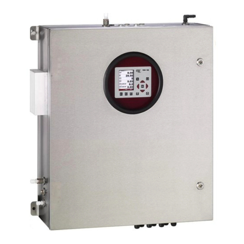
The instrument is intended for analyzing the composition of syngases and
determine the concentration of several components like CH4, CO2, O2 and H2. The
instrument may optionally be equipped to monitor several sites in time sharing
technique (cyclical one by one sampling).
In particular, the instrument is not foreseen to serve as a gas detector or as a safety
device.
In case of not intended use the guarantee will void. Regular controls, inspections
and the exchange from polluted and exhausted filters by the operator are also an
import - see chapter 9 regular
maintenancework.
The analyzer is an extractive measuring system. It has maximal 4 sample gas inlets,
to measure the gas concentration from 4 differentsample points, one by one. It has
an internal gas pump to suck the sample gas from the sampling points. After the
measurement, the samplegas is vented throughthe sample gasoutlet (Vent).
All sample points are equipped with a flow restrictor orifice, which allows also
sampling the gas from the higher-pressure gas pipe of the engine, while limiting
the maximum amountof gas in caseof internal cabinet pipingleakage.
2.1. Position of the gas in and outlets
1
2
3
4
4
5
6
7
11
8
9
10

MRU GmbH SWG 100 User Manual
Page 14 of143
1
Display (color, with backlight)
2
Keypad
3
Sample syngas inlet ports (1 to max 4 ), female G1/8” threads
4
Cabinet lock
5
Inlet cable glands M16 for I/O modules
6
Inlet cable gland M16 for mains power supply
7
Heat sink for gas cooler unit
8
Condensate outlet port, female G1/8” thread
9
Zero gas inlet port, female G1/8” thread
10
Calibration gas inlet port, female G1/8” thread
11
Vent outlet port, female G1/4”thread

MRU GmbH SWG 100 User Manual
Page 15of 143
2.2. Principle of operation
•Sample gas from one or more sampling points is fed into the analyzer by
dedicated ports. Internally mounted electric valves select one point at a
time tofeed sample gasto the analysisunit.
•The instrument is equipped with a non-dispersive infrared (NDIR) bench for
analysis of CO2 and CH4. Two separate infrared detectors for each CO2 and
CH4 are included, each operating with a different optical path length and
stabilized by referring to a reference detector. The IR source is a highly
efficient and stable IR emitter, pulsed at a frequency of several Hertz. By
design NDIR technique offers good stability and selectivity together with
long life time of sensor (only limited by corrosion or dust, which can be
prevented or removed byregular servicing the instrument).
•The instrument is optionally equipped with a number of electro-chemical
sensors ECS in order to detect gas components like oxygen O2 or. Those
sensors offer a reliable and effective way to detect the target gases. They
are typically of limited life time (several years) but may be easily replaced
once the end-of-lifeis reached.
•In regular time intervals (user settable), the instrument automatically
switches to purge the sensors with fresh (ambient) air for re-adjust the zero
point.


MRU GmbH SWG 100 User Manual
Page 17of 143
2.3. Marking and range of application
The analyzer is operating in a temperature range of - +45°C with intern
cabinet heater.
The specifications of the analyzer are:
Main power supply:
230 VAC / 50 Hz
Power consumption:
36 VA
Protection class:
IP65
Fuses:
230 VAC/ 50Hz / 6 A
Data output interface:
20 mA / analogoutputs
RS485 ModbusRTU
2.4. Possible applications and analyzer options
The syngas analyzer SWG100 is the industrial measuring solution to be used at all
hazardous zone 2areas of:
biogas (anaerobicdigestion) plants
cogeneration heat andpower engines (CHP)
municipal or industrial waste water treatment sites
coal seam gas sites (coal bed methane)
food and animalwaste processing plants
biomethane (gas togrid) plants
landfill sites
2.5. Features
This analyzer can be equipped with additional options and/or additional
accessories tofull fill multiple other measuring tasks such as
H2Slow measurement withprotected EC cell using cutoff solenoid valve and
air
purge pump
H2Shigh measurement with EC cell
H2 measurement with ECcell
CO measurement with ECcell
Multiple sampling point switchover from 2x up to maximum 4x sites
Module with 4 channel analog outputs/inputs 4-
alarm
relays
Converter moduleof RS485 into Profibus
Cabinet heater forfreeze protection
Ask our sales representatives for available options and accessories or check out our
MRUwebsite.

MRU GmbH SWG 100 User Manual
Page 18 of143
3. Scope of supply and delivery
The deliverycontains thefollow components:
•Analyzer, with a stainless steel case.
•A stainless-steel thread filter for the zero gas inlet, with a G1/8 inch male
thread.
•Flow restrictor orifices for the sample gas inlets, with a G1/8 inch female
thread. The number of flow restrictors is depended from the numberof gas
sample inlets.
•A fitting for the gasoutlet (vent), with a G1/4 inch male thread.
•Mountingmaterial.
•Optional: Flame arresters for the sample gas inlets, with a G1/4 inch male
thread.
Quantity
Description
Position
1 piece
1/8 G outlet thread
for DN4/6mm
Condensate outlet (4)
1 piece
¼ G outlet thread
90°
Sample gas outlet (VENT)
(5)
2 pieces + 1
for every
extra sample
gas inlet
1/8 G outlet thread
/ DN 4/6mm
Sample gas inlet (1)
Calibration gas inlet (2)
1 piece
Filter 1/8 G outlet
thread
Zero gas inlet (3)
1 piece
Cabinet key
Cabinet locks
2 pieces + 1
for every
extra sample
gas inlet
Copper seals for
the restrictor
orifice.
Sample gas inlet (1)
Calibration gas inlet (2)

MRU GmbH SWG 100 User Manual
Page 19of 143
3.1. Material required for the installation (not scope of supply)
Material for tubing or hosing the sample gas inlets and outlet.
•
For the sample gas inlets:
Flexible PTFE tube or stainless steel tubing with
a diameter of 4/6 mm. It could be necessary to install a heated sample line
on the tubes, toprotect the sample gas from freezing.
•
For the sample gas outlet (Vent):
Flexible PTFE tube with a diameter of
8/10 mm. It could be necessary to install a heated sample line on the
flexible tube, to protect the vent gas pipefor freezing.
•
For the condensate outlet:
Flexible tube with a diameter of 4/6 mm. It
could be necessary to heat the condensate tube to prevent that the
condensate forfreezing.
Power supply lines and signal lines
•Cable for power supply: Cable type: H 07 RN-F 5 G0,75 mm²
•
•Signal linesfor ModbusRTU digitaltransfer.

MRU GmbH SWG 100 User Manual
Page 20 of143
4. Installation manual
4.1. Content of your order
Your analyzer is delivered in a carton box and is protected with special edged
protectors. Please do preserve the packing of your analyzer, for possible back
shipment.
4.2. Installation rules to guarantee explosion protection
The analyzer has an ATEX Class 2 certification. To guarantee, that the analyser can
be operated safely in this area, please follow the rules during the mounting and the
operationof the analyser.
4.3. Prerequisites for installation
DANGER
Explosion hazard
Before start the mounting and installation work, detect the atmosphere with a
certificate gasdetector.
CAUTION
Only educated staff should mounting the analyzer on the stack.
NOTE
Important
The mountingshould be done in pairs.
A measurement point mustconform some criterions:
•The measurement place mustbe safeguarding andeasily accessible.
•The measurement place musthave enough space forinstallation and
maintenance works.
•The place should be protected for direct sunlight, rain and squalls.
•The area around theanalyzer must have enough space.
Other manuals for SWG 100
1
Table of contents
Other mru Measuring Instrument manuals

mru
mru AIR fair SWG 100 biogas User manual

mru
mru Vario Luxx User manual

mru
mru SPECTRA plus User manual

mru
mru OPTIMA Biogas User manual

mru
mru SWG100 BIOGAS User manual

mru
mru SWG100 CEM User manual

mru
mru OPTIMA7 biogas User manual

mru
mru NOVA compact User manual

mru
mru 400GD User manual

mru
mru AIR fair OPTIMA 7 User manual