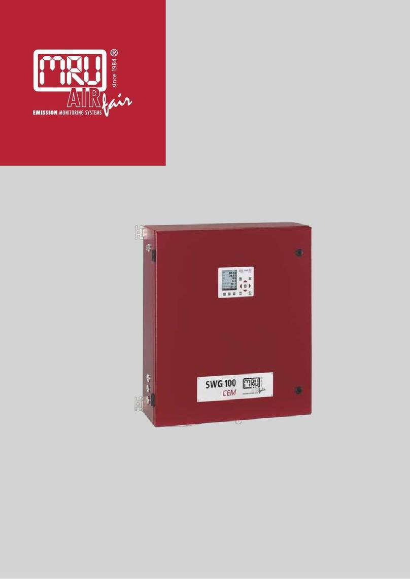
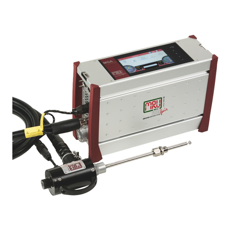
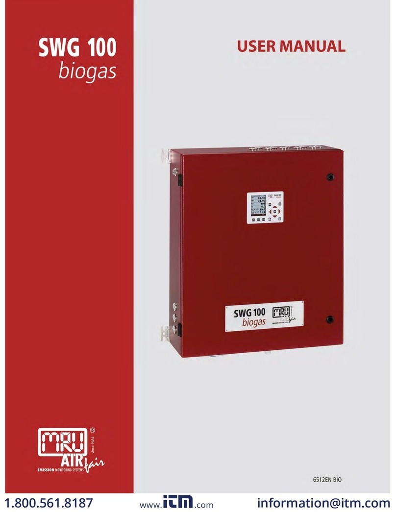
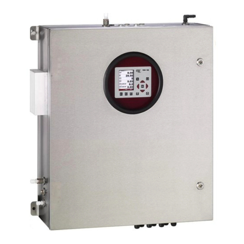
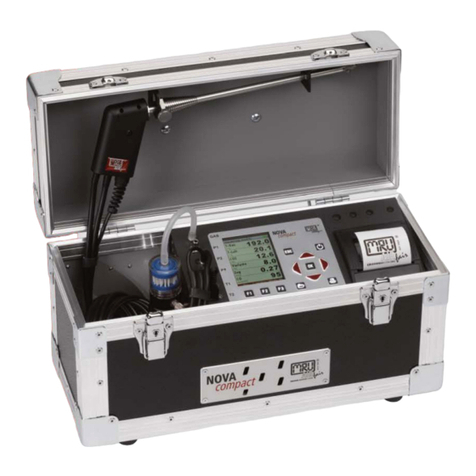
mru SWG100 BIOGAS User manual

9512EN- BIO
SWG100 BIOGAS
USER MANUAL

USER MANUAL SWG100
Page 2of 158

USER MANUAL SWG100
Page 3of 158
Content
1General Information....................................................................................................6
1.1. Weather and environmental conditions.....................................................6
1.2. Installation instructions ....................................................................................6
1.3. General important instructions for the plant operator ..........................6
1.4. Important information about the user’s operation manual.................8
1.5. Safety Information ..............................................................................................8
1.6. Packing ................................................................................................................ 13
1.7. Return of hazardous waste ........................................................................... 13
1.8. Return of analyzer............................................................................................ 13
1.9. MRU Warranty conditions ............................................................................. 13
2Analyzer Description................................................................................................ 15
2.1. Intended use...................................................................................................... 15
2.2. Type plate ........................................................................................................... 15
2.3. Possible applications and analyzer options............................................ 17
2.4. Principle of operation..................................................................................... 17
2.5. Special functions of the analyzer................................................................ 19
2.6. Physical characteristic of the gas analyzer .............................................. 20
3Scope of supply and delivery................................................................................ 23
3.1. SD-card content................................................................................................ 24
4Installation manual................................................................................................... 25
4.1. Overview............................................................................................................. 25
4.2. Select measurement point............................................................................ 27
4.3. Installation of the analyzer............................................................................ 28
4.4. Installation: Sample gas outlet (VENT) ...................................................... 32
4.5. Installation: Calibration gas / zero gas and condensate outlet ........ 33
4.6. Option: Autocalibration by using several gas cylinders...................... 34
4.7. Connection of main power supply............................................................. 35
4.8. I/O modules: Installation and setting........................................................ 37
5Operation of the analyzer (HMI) .......................................................................... 39
5.1. Display and keypad ......................................................................................... 39
6Analyzer commissioning manual ........................................................................ 41
6.1. Check country and language....................................................................... 41
6.2. Check date and time of the instrument.................................................... 41
6.3. Configuration of the alarm relays............................................................... 42
6.4. Configuration of the Modbus ...................................................................... 44
6.5. Autocalibration: Explanation of the software operation.................... 45
7Binding to a process control system: I/O modules........................................ 47
7.1. Position of the IO module inside the analyzer ....................................... 47
7.2. Pin assignment.................................................................................................. 48
7.3. Analog outputs 4-20 mA ............................................................................... 50
7.4. Alarm outputs ................................................................................................... 56
7.5. Analog inputs (4-20 mA)................................................................................ 61
7.6. Configuration of the external control (Option: IO module)............... 66
7.7. Analyser states .................................................................................................. 73
7.8. Cycle configuration ......................................................................................... 74
7.10. Administrator PIN code ............................................................................. 81
USER MANUAL SWG100
Page 4of 158
7.11. Power-On of analyzer..................................................................................81
8Operating the analyzer............................................................................................82
8.1. General process of the measurement cycle.............................................82
8.2. Protective measures for electrochemical H2S sensors.........................85
8.3. Data Storage Menu...........................................................................................87
8.4. Extra menu: Overview .....................................................................................91
8.5. Update the firmware.....................................................................................101
9Service and maintenance.....................................................................................105
9.1. Preparing and information about the maintenance.......................... 105
9.2. Regular maintenance work by the operator.........................................105
9.3. Position and overview of the service-parts........................................... 106
9.4. Cleaning and decontamination ................................................................ 113
9.5. Troubleshooting.............................................................................................113
10 Technical specification .....................................................................................114
10.1. Technical specification: Electrochemical sensors........................... 117
10.2. Technical specification: NDIR-benches ..............................................118
11 APPENDIX..............................................................................................................119
11.1. Spare parts list ............................................................................................119
11.2. Mechanical dimensions...........................................................................122
12 Purchase options of the analyzer.................................................................. 123
12.1. Option: Electric sample gas cooler ...................................................... 123
12.2. Option: Cabinet heater ............................................................................ 124
12.3. Option: Flame arrester .............................................................................125
12.4. Option: Multiple sample point switching and monitoring (time
sharing) 127
12.5. Option: Gas detector (%LEL CH4) to monitor air inside analyzer
cabinet 128
12.6. Option: Extra IO module with 4 channel 4-20 mA.......................... 132
12.7. Option: H2S electrochemical cell measurement 0-
2000ppm/4000ppm...................................................................................................133
12.8. Option: RS485 Profi-Bus converter ......................................................134
12.9. Option: RS485 to Ethernet converter..................................................135
12.10. Configuration of the Ethernet module...............................................136
12.11. Option: NDIR-bench for CH4/CO2 analysis, 0-100% / 0-100% ...144
12.12. Option: H2 thermal conductivity detector measurement 0-100%
150
12.13. Option: NDIR-bench for 0-3.000ppm CO2/0-3.000…30.000ppm
CH4 151
12.14. Option: Dilution-unit for H2S and CO electrochemical sensors.152
13 Declaration of conformity ...............................................................................158

USER MANUAL SWG100
Page 5of 158
Inspect Shipment for Damage
Carefully inspect the entire shipment for damage in the presence of the
shipper’s agent, removing packaging material if necessary. Note any
damage to packaging and/or goods on Packing List and have it signed by
the shipper’s agent prior to accepting the shipment. Submit damage claim
to MRU immediately.
NOTE: Damage claims not received by MRU within 3 days of receipt of
shipment will not be accepted.
The products described in this manual are subject to continuous
development and improvement and it is therefore acknowledged that this
manual may contain errors or omissions. MRU encourages customer
feedback and welcomes any comments or suggestions relating to the
product or documentation.
Please forward all comments or suggestions to the Customer Feedback
Department at the following address:
MRU GmbH
Fuchshalde 8 + 12
74172 Neckarsulm / Obereisesheim
GERMANY
Fon (+49) 71 32 99 62 0 (Reception)
Fon (+49) 71 32 99 62 61 (Service)
Fax (+49) 71 32 99 62 20
Email: info@mru.de
Homepage: www.mru.eu
This manual is intended solely as a guide to the use of the product.
MRU shall not be liable for any loss or damage whatsoever arising from
content errors or misinterpretation of information’s from this manual or any
mis-use resulting from the use of this manual.
FOR MORE INFORMATIONS ABOUT COMPANY MRU PLEASE VISIT OUR
WEBSITE www.mru.eu

USER MANUAL SWG100
Page 6of 158
1General Information
1.1.Weather and environmental conditions
The SWG100 BIOGAS analyser is designed for ambient temperatures of +5°C
to +45°C (without cabinet heater) resp. -10°C to +45°C (with cabinet heater).
The analyser is designed for indoor mounting. In case of outdoor mounting
it is important that the analyser is sufficiently protected against rain, sun and
wind. In case of outdoor mounting under extreme environmental conditions
like high humidity, salty sea air, etc. further protective measures are
necessary. These should be clarified with the manufacturer (MRU).
Any additional protective measures for outdoor mounting have to be
provided by the plant operator. The manufacturer (MRU) consults the plant
operator in choosing appropriate protective measures.
NOTE
The SWG100Biogas analyser is designed for sampling biogas
with condensate of max. 14ml/min.
If the sample biogas will be very wet (high condensate of more
than 14ml/min), then – to protect the SWG100-Biogas analyser
–
please consider special precautions to remove the
condensate.
If you not have your own feasible solution for this topic, please
ask MRU.
1.2.Installation instructions
Installation instructions, which are described in chapter 3 of the operation
manual, have to be strictly adhered to.
WARNING
Please check correct installation before powering up the
analyzer!
Please operate the analyzer only in upright position!
1.3.General important instructions for the plant operator
To guarantee continuous operation of the SWG100 BIOGAS analyser, the
functions, processes and operation of the analyser have to be monitored
regularly by the plant operator – especially in case of any initial installation.
Thus, it will be possible to take suitable measures to improve the availability
and life time of the analyser.
As the plant operator gains more experience concerning the maintenance
requirements of the analyser, the monitoring frequency may be reduced to
more extended periods of time.

USER MANUAL SWG100
Page 7of 158
It is important that the filter-units, listed in chapter 9.1 of the operation
manual, are checked regularly and, if necessary, service parts are changed.

USER MANUAL SWG100
Page 8of 158
NOTE
In case of
not intended
use the guarantee will void. Regular
controls, inspections and the exchange from
polluted and
exhausted filters by the operator are also an important part of
the determinations “not determined use”- see chapter 9.1
regular maintenance work.
1.4.Important information about the user’s operation manual
The users/operation manual is an important part of this delivery. It will
explain how to use this analyzer properly and sets forth safety and
environmentally friendly procedures.
It is the responsibility of all users to read and familiarize themselves with this
manual, paying particular attention to the safety instructions.
The most important safety details are clearly marked with an attention sign.
1.5.Safety Information
The following safety procedures must be followed at all times. They are
significant and essential part of this manual. Failure to follow safety
procedures can result in the loss of your warranty claims.
Biogas or other similar gases (landfill gas, bio-methane, coal seam gas etc) is
containing flammable gas component CH4 and toxic gas component as well
(H2S and CO2).
Analyzer is continuously sampling a certain volume (approx. 50l/h) of the
sample gas, and is venting it to ambient air.
For this reason, there are two aspects which must be considered:
Toxicity danger of sample gas
WARNING
Toxic gas
Sample gas can contain toxic substances, which are harmful
for health and can even cause death.
• It is the responsibility of analyzer user to ensure that person is skilled and
trained in safety aspects of gases being analyzed and procedures to
follow while using this instrument.
• Local regulations for possible exposure to toxic gases has to be known
and obeyed by the user of the analyzer
• Using a personal gas detector inside the biogas plant is highly
recommended since
H2Sin higher (very dangerous) concentration cannot be detected by
human nose. Only small concentrations around few ppm can be detected
by human nose

USER MANUAL SWG100
Page 9of 158
• CO2gas is heavier than air and therefore operator shall avoid working at
underground levels. Beware of that CO2is also odorless!
• It is not allowed to use the biogas analyzer in confined space or
rooms
without forced ventilation.
• Sample gas exiting the analyzer will flow in to the ambient air and
only outdoor use
or forced ventilation rooms are suitable for using the biogas analyzer.
no dangerous quantities poisonous or injurious gases or substances are
liberated under NORMAL CONDITIONS
List of poisonous or injurious gases which are normally present in the
sample gas (Biogas)
Gas
liberated quantities
sample gas (total)
<100ml/day
CH4 (methane)
<75ml/day
CO2 (carbon dioxide)
<55ml/day
H2S (hydrogen sulfide)
<0,5ml/day
H2 (hydrogen)
<1ml/day
NH3 (ammonia)
<1ml/day
Flammable gas
WARNING
Flammable gas
Biogas contains Methane (CH4), which can be flammable.
Regarding flammable gases (e.g. CH4methane) and operating-instruments
in the hazardous areas, the user must also be able to recognize the area
classification and be aware of using the instrument there. This area
classification is country specific, please observe and adhere to it.
• Stationary analyzers are allowed to be mounted in hazardous area zone 2
only if they have the certificate of compliance. These instruments shall
never be located in confined places or rooms without forced ventilation.
Only trained personnel should carry out installation of stationary instrument
and/or maintenance, service and repair. Opening the stationary analyzer
cabinet can expose personnel to injuries and shocks from electrical voltage!

USER MANUAL SWG100
Page 10 of 158
Safety regulations
MRU GmbH assures that the analyzer complies to the essential requirements
of the legal regulations of the member states of the electro-magnetic
compatibility (89/336/EWG) and to the low-voltage regulations (3/23/EWG).
Specific safety regulations
No part of the analyzer, or any other metal parts & accessories shall be used
as electric conductors.
The analyzer shall not be used in or under water.
The analyzer shall not be placed near or directly exposed to open fire or
heat.
The analyzer shall avoid dropping.
WARNING
Acid substances
Moisture or condensate, being pumped out of the condensate
outlet port can be slightly acidic.
•In case of skin contact IMMEDIATELY: clean affected
parts of the body.
•Avoid getting liquid in eyes.
Please carefully clean all parts that come into contact with the
condensate.
WARNING
Hazardous Live
Power down the system and disconnect from mains to avoid
access to live parts by using a tool.

USER MANUAL SWG100
Page 11 of 158
Battery cell
The analyzer contains battery cells at the following positions:
•Main board (1).
Follow steps must be aware:
WARNING
Switch off the power of the device
Before removing the battery the device must be switched off.
WARNING
Educated staff
It is recommended that only trained staff exchange the battery
cell from the analyzer.
WARNING
Charging
Overcharging, short circuiting, reverse charging, mutilation or
incineration of the cells must be avoided to prevent one or
more of the following occurrences; release of toxic materials,
release of hydrogen and/or oxygen gas, rise in surface
temperature.
WARNING
Watch out of damage
If a cell has leaked or vented, it should be replaced immediately
using protective gloves.
1

USER MANUAL SWG100
Page 12 of 158
WARNING
Replacement of empty or damage cells
If and when necessary, these cells must be replaced with
identical new ones from the same manufacturer. If a cell to be
replaced is connected with other cells in series, it is
recommended that the other cells be replaced with new ones at
the same time.
WARNING
Watch out polarity
Reverse polarity installation of the cell in the end product must
be avoided.
WARNING
Ventilation
Cell compartments containing these cells must be provided
with means of ventilation to prevent possible accumulation of
any released gases under abnormal conditions.

USER MANUAL SWG100
Page 13 of 158
1.6.Packing
Packing regulation of 12.07.1991
If your local waste facility does not accept MRU packing materials for
disposal, you may return it to MRU or our local sales representative. Packing
materials returned to MRU must be returned prepaid.
1.7.Return of hazardous waste
Waste Disposal/Returns/Warranty -
MRU GmbH is required to accept the return of hazardous waste such as
electro-chemical sensors that cannot be disposed of locally. Hazardous
waste must be returned to MRU prepaid.
1.8.Return of analyzer
MRU GmbH is required to accept the return, for proper disposal, of all
analyzers delivered after 13th of August 2005. Analyzers must be returned to
MRU prepaid.
1.9.MRU Warranty conditions
The SWG100 BIOGAS warranty is 12 months.
1. The warranty on spare parts is 6 months.
2. The term of the warranty conditions starts as of the invoice date.
3. The warranty is void under the following conditions:
•Improper use.
•Improper application.
•Improper mounting.
•Deliberate or negligent destructions.
•External influence like droping, impact, solvents, acids, gases, or
transport damages. This includes damage, which is caused by
exposure to high pollution and/or moisture (condensate) in the gas
path.
4. As well excluded from the guarantee conditions are typical consumable-
and spare parts.
5. Use of original MRU consumable parts and sensors is required to maintain
the warranty.
6. Removal of tampering of the serial number type plate will void the
warranty.
7. The service of a guarantee conditions will not enlarge the guarantee time.
Demands because of consequential damages are excluded.
8. MRU is not responsible for the transport costs for the warranty or
replacement.
9. MRU reserves the right, to determine individual conditions or exceptions.
These will be separately communicated.
MRU GmbH
01.09.2014

USER MANUAL SWG100
Page 14 of 158

USER MANUAL SWG100
Page 15 of 158
2Analyzer Description
2.1.Intended use
The instrument is intended for analyzing the composition of biogases / landfill gases and
determine the concentration of several components like CH4, CO2, O2 and H2S. The
instrument may optionally be equipped to monitor several sites in time sharing technique
(cyclical one by one sampling).
In particular, the instrument is not foreseen to serve as a gas detector or safety device.
In case of unintended use, the warranty is void. Regular controls, inspections and the
replacement of polluted and exhausted filters by the operator are also an important part of
proper use. See chapter 9.1 regular maintenance work.
2.2.Type plate
The type plate of the analyzer contains important information about the analyzer. It can be
found:
•The serial-no.
•The power supply.
•The installed measurement options.
•Date built.
The table below shows, which kind of measurement options may be installed in the
analyzer.
1.
O2, H2S, H2,
CO
Electrochemical sensor

USER MANUAL SWG100
Page 16 of 158
2.
CH4/CO2
NDIR-bench
3.
H2
Thermal conductivity detector.

USER MANUAL SWG100
Page 17 of 158
2.3.Possible applications and analyzer options
The biogas analyzer SWG100 is the industrial measuring solution to be used
with:
• biogas (anaerobic digestion) plants
• cogeneration heat and power engines (CHP)
• municipal or industrial waste water treatment sites
• coal seam gas sites (coal bed methane)
• food and animal waste processing plants
• biomethane (gas to grid) plants
• landfill sites
This analyzer can be equipped with additional options and/or additional accessories to full
fill multiple other measuring tasks such as
• CH4 and CO2NDIR measurement
• O2measurement with long-life EC cell
• H2Slow measurement with protected EC cell using cutoff solenoid valve and air
purge pump
• H2Shigh measurement with EC cell
• H2measurement with EC cell
• CO measurement with EC cell
• Electric gas cooler (Peltier) with automatic condensate draining pump
• Multiple sampling point switchover from 2x up to a maximum of 10x sites
• Module with 4 channel analog outputs/inputs 4-20mA, with 2x “fail safe” alarm
relays
• Converter module of RS485 into Profibus
• Cabinet heater for freeze protection
Ask our sales representatives for available options and accessories or check out our MRU
website.
2.4.Principle of operation
•Sample gas from one or more sampling points is fed into the analyzer by dedicated
ports. Internally mounted electric valves select one point at a time to feed sample
gas to the analysis unit.
•The instrument is equipped with a non-dispersive infrared (NDIR) bench for analysis
of CO2 and CH4. Two separate infrared detectors for each CO2 and CH4 are
included, each operating with a different optical path length and stabilized by
referring to a reference detector. The IR source is a highly efficient and stable IR
emitter, pulsed at a frequency of several Hertz. By design NDIR technique offers
good stability and selectivity together with long life time of sensor (only limited by
corrosion or dust, which can be prevented or removed by regular servicing the
instrument).
•The instrument is optionally equipped with a number of electro-chemical sensors
ECS in order to detect gas components like oxygen O2 or H2S. Those sensors offer a
reliable and effective way to detect the target gases. They are typically of limited life
time (several years) but may be easily replaced once the end-of-life is reached.
•In regular time intervals the instrument automatically switches to purge the sensors
with fresh (ambient) air for re-adjust the zero point.

USER MANUAL SWG100
Page 18 of 158
Picture above: Sample gas flow diagram.
The picture below shows how theanalysershould be piped. A ball valve and aprefilter is
recommended.

USER MANUAL SWG100
Page 19 of 158
2.5.Special functions of the analyzer
H2Slow sensor protection (optional)
The instrument may be optionally equipped with a H2Slow sensor. As this sensor typically
shows limited life time when experiencing high H2S concentrations, some precautions are
taken to protect the sensor:
•The instrument is equipped with a cut-off solenoid valve and air purge pump to
protect the H2Slow sensor, without impacting the results of all other sensors.
•The purge unit is always activated after 3-10 minutes of active sensor measuring
time.
•The measuring time of the H2Slow sensor may be limited to less than 10 minutes by
user setting
•The H2Slow sensor may optionally not be included in all measuring cycles of
sampling points. Instead the user may configure that the H2Slow sensor is active only
added at some of the measurement cycles.

USER MANUAL SWG100
Page 20 of 158
2.6.Physical characteristic ofthe gas analyzer
Top view
Front view
Reference:
1. Gas inlet (default x1/optional max.10) 4. Suspension for wall mounting
2. Cabinet lock
1
2
3
4
Table of contents
Other mru Measuring Instrument manuals

mru
mru AMPRO 2000 GOLD User manual

mru
mru Optima 7 User manual

mru
mru VARIOluxx User manual

mru
mru MGAprime User manual

mru
mru Air Fair MGAprime User manual

mru
mru SWG100 BIOEX User manual

mru
mru SWG 100 biogas User manual

mru
mru NOVAplus BIOGAS User manual

mru
mru SYNGAS VARIOluxx User manual

mru
mru NOVAplus User manual