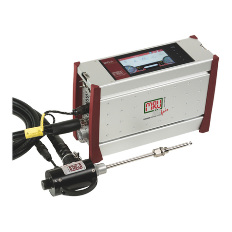
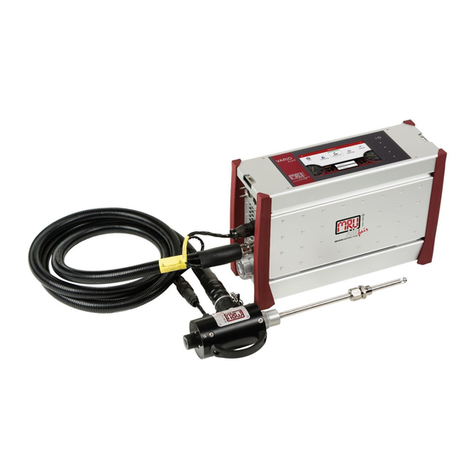
mru NOVAplus User manual

9472EN
NOVAplus
USER MANUAL

USER MANUAL NOVAplus
MRU GmbH, D-74172 Neckarsulm 2 / 95
Producer:
Legal notices / Intellectual property rights comments
Original user manual
© 2022 by MRU
No part of this manual my be published in any form (print, fotocopy, electronic media or
any other publication form) without a written approval by the publisher.
All user trade marks and name mark descriptions, even those which are not marked as
such, are properties of the respective owners.
Edition: 2022-05-17-V1.11.EN

USER MANUAL NOVAplus
MRU GmbH, D-74172 Neckarsulm 3 / 95
Table of content
1Information for product and safety .....................................................7
1.1. Safety manual .......................................................................................................7
1.2. Safety precautions...............................................................................................7
1.3. Ensure safety .........................................................................................................8
1.4. Important general information EN 50379 and VDI 4206........................9
1.5. User guideline for rechargeable batteries...................................................9
2Introduction ........................................................................................ 10
2.1. Intended use ...................................................................................................... 10
2.2. About us............................................................................................................... 12
2.3. Packaging............................................................................................................ 13
2.4. Return of hazardous materials ..................................................................... 13
2.5. Return of electronic equipment .................................................................. 13
3Description.......................................................................................... 14
3.1. Measurement principle .................................................................................. 15
Gas flow diagram with condensate separator ................................................ 15
Gas flow diagram with gas cooler....................................................................... 16
3.2. Remote control unit (RCU)............................................................................. 17
3.3. Base unit condensate separator .................................................................. 18
3.4. Base unit with condensate separator ........................................................ 19
Connectors depending on the options (condensate separator).............. 20
3.5. Base unit with gas cooler (option) .............................................................. 21
Connectors depending on the options (gas cooler)..................................... 22
Water stop (option).................................................................................................. 22
3.6. Gas sampling probes....................................................................................... 23
4Operating ............................................................................................ 24
4.1. Display.................................................................................................................. 24
4.2. Keypad.................................................................................................................. 25
4.3. Connection Remote control unit (RCU) to base unit............................ 26
Declaration of symbols ........................................................................................... 26
Connecting base unit to RCU................................................................................ 26
4.4. Reset and Blink codes...................................................................................... 28
4.5. Menu structure.................................................................................................. 28
5First usage ........................................................................................... 30
5.1. Preparatory steps.............................................................................................. 30
5.2. Analyser settings............................................................................................... 30
5.3. Measurement settings .................................................................................... 31
5.4. Switch-On protection...................................................................................... 32
5.5. Print-out settings.............................................................................................. 32
5.6. Bluetooth settings............................................................................................ 33
5.7. Setting date and time...................................................................................... 33
5.8. Configuring Measurement Programs........................................................ 34

USER MANUAL NOVAplus
MRU GmbH, D-74172 Neckarsulm 4 / 95
5.9. Setting CO limit value ......................................................................................34
5.10. Select fuel types and 02 reference...............................................................35
Adding fuels to Fuel type selection.....................................................................35
Setting 02reference...................................................................................................36
5.11. Defining user fuels type ..................................................................................36
5.12. Defining measurement window...................................................................37
5.13. Configuring zoom window ............................................................................38
5.14. Changing measurement program names.................................................39
6Preparing measurement .................................................................... 40
6.1. Ensure power supply........................................................................................40
6.2. Automatic Auto-off function .........................................................................40
6.3. Measuring with grid power supply / Battery charging.........................40
6.4. Battery charge condition ................................................................................40
6.5. Operating temperature...................................................................................41
6.6. Controlling Condensate separator (water trap)......................................41
6.7. Connections and tightness ............................................................................42
6.8. Automatic zero-point setting........................................................................42
Repeating the zeroing..............................................................................................43
6.9. Zeroing with the 3-gas-NDIR bench............................................................43
7Performing measurement.................................................................. 44
7.1. Selecting the measuring program...............................................................44
7.2. Core flow search.................................................................................................45
7.3. Measured value display...................................................................................46
7.4. CO purging (optional)......................................................................................48
7.5. CO/H2 and CO high (optional)......................................................................48
7.6. Specific measurement applications ............................................................49
30 sec. average value calculation according 1. BImSchV_2010.................49
Annular-gap measurement program..................................................................49
Test program...............................................................................................................50
Performing Ambient CO Test.................................................................................51
7.7. Temporary buffer...............................................................................................51
Store measured values in the buffer ...................................................................52
Overwrite measured values in buffer..................................................................53
7.8. Storing measured values ................................................................................53
Entering T-boiler, Soot No. and Derivative........................................................54
7.9. Printing measurement values .......................................................................55
7.10. Terminate measurement ................................................................................55
7.11. Last measurement values...............................................................................55
7.12. Pressure measurement....................................................................................56
7.13. Differential temperature measurement ....................................................57
7.14. Performing measurements on CHP units (option).................................57
8Data Storage........................................................................................ 59
USER MANUAL NOVAplus
MRU GmbH, D-74172 Neckarsulm 5 / 95
8.1. Organizing data storage................................................................................. 59
8.2. Calling up information about data storage ............................................. 59
8.3. Site administration........................................................................................... 60
Create new site .......................................................................................................... 60
View sites ..................................................................................................................... 61
Searching site............................................................................................................. 61
Changing sites ........................................................................................................... 62
Deleting sites.............................................................................................................. 63
Data transfer using SD card (option).................................................................. 63
Importing sites........................................................................................................... 64
Exporting sites ........................................................................................................... 66
Exporting combustion measurements.............................................................. 66
Exporting differential pressure measurements.............................................. 67
8.4. Measurements in Data storage.................................................................... 67
Viewing Measurements .......................................................................................... 67
Deleting measurements......................................................................................... 68
Transferring measurements to SD-Card (Option).......................................... 69
8.5. Data transfer to the PC (Sweeping district management pro-grams)
69
9Extras / Adjustments .......................................................................... 71
9.1. User definable Logo print out ...................................................................... 71
9.2. Service calibration menu ............................................................................... 73
9.3. Default settings ................................................................................................. 74
9.4. Service values RCU / Service values Base unit......................................... 74
9.5. Performing leak test......................................................................................... 76
9.6. Contents SD card.............................................................................................. 77
9.7. Contents Analyser info.................................................................................... 77
Options list remote control ................................................................................... 77
Options list base unit............................................................................................... 78
9.8. Self diagnostics.................................................................................................. 78
10 Maintenance and care .................................................................... 79
10.1. Cleaning............................................................................................................... 79
10.2. Maintenance....................................................................................................... 79
10.3. Service messages.............................................................................................. 79
11 Appendix ......................................................................................... 80
11.1. Technical data.................................................................................................... 80
General data ............................................................................................................... 80
Gas sampling and conditioning........................................................................... 81
Measurement accuracy data................................................................................. 81
11.2. Calculated values.............................................................................................. 86
Data communication............................................................................................... 88
11.3. Analysis and calculations ............................................................................... 88

USER MANUAL NOVAplus
MRU GmbH, D-74172 Neckarsulm 6 / 95
11.4. Fuel type list.......................................................................................................89
11.5. Text input .............................................................................................................90
11.6. Asking user for decision ..................................................................................90
11.7. Firmware update ...............................................................................................91
11.8. Troubleshooting ................................................................................................93
Troubleshooting the analyser ...............................................................................93
Troubleshooting condensate separator ............................................................93
12 Declaration of conformity............................................................... 94

USER MANUAL NOVAplus
MRU GmbH, D-74172 Neckarsulm 7 / 95
1Information for product and safety
1.1. Safety manual
All general information and safety precautions of MRU products are listed in
the supplied separate safety manual.
Therefore, this manual must be read and observed before the first use of the
instrument.
Instrument-specific safety and warning requirements in this manual are pre-
fixed before dangerous actions.
1.2. Safety precautions
The used categories of safety precautions are here explained once more
DANGER
Identifies an immediate, impending hazard that, if
ignored, will result in severe bodily injuries or death.
WARNING
Identifies an immediate, impending hazard that, if
ignored, may result in severe bodily injuries, material dam-
age or death.
CAUTION
Identifies a possibly dangerous situation that, if
ignored, may result in minor injuries.
ATTENTION
Identifies a possibly harmful situation that, if ignored, may
result in damages to the device or its
surroundings.
NOTE
Identifies user tips and other especially important infor-
mation.
The explanation of safety notices:
CAUTION
HOT – danger of burns and fire hazards from gas ex-
traction probe.
Physical harm and property damage can be caused.
►Cool down the probe tube.

USER MANUAL NOVAplus
MRU GmbH, D-74172 Neckarsulm 8 / 95
1.3. Ensure safety
►Please read the user manual completely before the first use.
►Only use the analyser for the intended use and within the parameters
specified in the technical data.
►Do not use any violence.
►Avoid falls.
►Do not put the analyser into use, if the housing, power supply unit or sup-
ply leads are damaged.
►Do not store the analyser together with solvents. Do not use
desiccants.
►Only carry out maintenance and service work on this analyser as de-
scribed in the User Manual. Observe the prescribed action steps.
►Operate the analyser only in closed, dry rooms and protect it from rain
and moisture.
►When operating the analyser on mains power, operate it only with the
mains adapter supplied
►The analyser must not be located in the immediate vicinity of open fire or
great heat.
►Do not use the metal tube of the gas sampling probe or other metallic
parts / accessories as electrical conductors.
►Do not use the analyser in or under water.
►The specified temperature range of the gas sampling probe must not be
exceeded, otherwise the probe tube and temperature sensor will be de-
stroyed.
►Moisture, being pumped out of the condensates trap can be slightly
acidic.
In case of skin contact IMMEDIATELY: clean affected parts of the body.
Avoid getting liquid in eyes. Please carefully clean all parts that come into
contact with the condensates.
►After measurement, vent the analyser with ambient air and allow the
probe to cool. A hot probe could cause burns or ignite flammable mate-
rial.
►Electrochemical sensors are by their operating principle not only sensitive
to the gas they are intended for, but for other gases as well. This cross
sensitivity is compensated by MRU for the typical application of flue gas
analysis. However, unusual high concentration levels of single gas com-
ponents might lead to a reduced measurement accuracy of other gas
components and to a temporary change of the sensitivity of sensors,
which may require several hours recovery time.
Especially concentration levels as high as several % for single gas compo-
nents may affect the measurement of other gas components at ppm
level. Those applications need to be discussed with MRU in detail

USER MANUAL NOVAplus
MRU GmbH, D-74172 Neckarsulm 9 / 95
1.4. Important general information EN 50379 and VDI 4206
This analyser is not designed to be used for continuous measurements.
Before using the analyser verify the condition of the various parts of the ana-
lyser, such as the probe, the ambient air conditions, the condensate separa-
tor, star filter and the connectors for damage and/or blockages.
When starting up the analyser it will take between 1 – 3 minutes to set to zero
depending on the condition of the sensors and of ambient.
The minimum zeroing time of the analyser to achieve correct measurement
values can be expected by 1.5 minutes!
Caution: Exposure to acids; aggressive gases such as sulphur; vapours such
as thinners, gasoline, alcohol and paint, etc. can damage, reduce the life of,
or destroy the sensors.
The life of the sensors depends on how they are used, maintained and treated.
Typical average life expectations are: O2- 2 years; CO - 2 - 3 years and NO - 3
years.
The use of the analyser for regulatory purposes is subject to special regula-
tions (for example a periodical examination of the analyser). Please obtain the
appropriate regulations from your local responsible authority.
1.5. User guideline for rechargeable batteries
NOTE
The rechargeable batterie is installed inside the analyser
and is not accessible to the end customer. However, the
following instructions must generally be observed when
handling lithium-ion rechargeable batteries.
•This rechargeable battery can only be used in this analyser.
•Do not throw the rechargeable battery into a fire, charge it at high tem-
peratures and store it in a hot environment.
•Do not deform, short-circuit or modify the rechargeable battery.
•The rechargeable battery must not be used in or under water.
•Do not expose the rechargeable battery to strong mechanical forces and
do not throw it.
•Do not cut or squeeze the connecting cables of the rechargeable battery.
•Do not connect the (+) contact to the (-) contact or metal.
•Non-observance of the above guidelines can cause heat, fire and explo-
sions

USER MANUAL NOVAplus
MRU GmbH, D-74172 Neckarsulm 10 / 95
2Introduction
•This manual enables you to understand and safely operate this MRU Ana-
lyser.
•Please read this manual with great vigilant and get familiar with the
product before using it.
•This analyser may only be operated by competent personnel and for its
intended use.
•Please pay special attention to all safety directions and warnings to pre-
vent personal injuries and damaging of the product.
•We can’t be held responsible for any injuries and/or damages that occur
by not following the instructions in this manual.
•Always keep the manual near you when working with the analyser, to be
able to read instructions as needed. Please ensure to hand over all docu-
ments to when handing the analyser over to others.
2.1. Intended use
The main task of the analyser is in supporting the following applications:
•Precise control- and adjustment measurements for Gas-, oil or wood
fired burners
•Flue gas measurement according to 1. BImSchV and KÜO
The CO sensor is protected with the automatic purging pump.
This analyser can be equipped with additional options and/or additional ac-
cessories to full fill multiple other measuring tasks such as
•Mobile Gas detector (Option HC-sniffer)
•Anemometer (Option Flow velocity, using either a Pitot tube or a vane)
•Hygrometer/Barometer (Option ambient humidity including tempera-
ture and barometric pressure)
•Leak testing device (Option external pressure sensor)
The multiple options and multiple connections possibilities of external sen-
sors often replaces the need of additional measuring equipment(s). Ask our
sales reps. for available options and accessories or check out our MRU web-
site.
The wireless remote unit offers the user a variety of advantages while meas-
uring. Especially in small rooms only the base unit will sit next to the boiler
while the user can operate the unit from a distance. Precise ambient air tem-
perature measurements can be done with either the base unit or remote
unit (RCU). The RCU can also be used as a standalone measuring and data
logging unit for differential temperature and differential pressure (and other
optional functions). With the optional available gas cooler with automatic
condensate draining pump the unit can also be used for long term measure-
ments

USER MANUAL NOVAplus
MRU GmbH, D-74172 Neckarsulm 11 / 95
The analyser is specifically not intended as a safety device or personal pro-
tective equipment.
The analyser should not be used as a warning device to warn people against
the presence of harmful gases.
The analyser must be used according to instructions for the intended use.
Our analysers are checked according to the following regulations:
VDE 0411 (EN61010) and DIN VDE 0701 before they leave the MRU GmbH
factory.
MRU technical products are designed and manufactured according to DIN
31000/ VDE 1000 and UVV = VBG 4 of the professional guilds for fine me-
chanics and electrical engineering.
MRU GmbH assures that the analyser complies to the essential requirements
of the legal regulations of the member states of the electro-magnetic com-
patibility (89/336/EWG)
WARNING
Risk from manipulations to the measuring device
Operational safety hazard
►Modifications or changes to the measuring device are
not allowed.

USER MANUAL NOVAplus
MRU GmbH, D-74172 Neckarsulm 12 / 95
2.2. About us
The analyser is produced by the MRU GmbH in Neckarsulm, Germany
(Founded in 1984), a medium sized company that specializes in developing,
producing and marketing high quality emission monitoring
analysers. MRU GmbH produces a wide range of instruments, from standard
analysers up to tailor made industrial analysers.
Plant 1: Sales, Service, R&D
Plant 2 (Production)
Fuchshalde 8 + 12
74172 Neckarsulm - Obereisesheim
GERMANY
Tel +49 71 32 99 62 0 (Front office)
Tel +49 71 32 99 62 61 (Service)
Fax +49 71 32 99 62 20
Email: info@mru.de
Site: www.mru.eu

USER MANUAL NOVAplus
MRU GmbH, D-74172 Neckarsulm 13 / 95
2.3. Packaging
Save the original carton and packing materials to prevent damage in transit
in case you need to return the unit to the factory.
2.4. Return of hazardous materials
Waste Disposal/Returns/Warranty - MRU GmbH is required to accept the re-
turn of hazardous waste such as electro-chemical sensors that cannot be dis-
posed of locally.
Hazardous waste must be returned to MRU prepaid.
2.5. Return of electronic equipment
MRU GmbH is required to accept the return, for proper disposal, of all analys-
ers delivered after 13th of August 2005. Analysers must be returned to MRU
prepaid.

USER MANUAL NOVAplus
MRU GmbH, D-74172 Neckarsulm 14 / 95
3Description
The main task of the analyser is in supporting the following applications:
•Precise control- and adjustment measurements for Gas-, oil or wood
fired burners
•Flue gas measurement according to 1. BImSchV and KÜO
The CO sensor is protected with the automatic purging pump.
This analyser can be equipped with additional options and/or additional ac-
cessories to full fill multiple other measuring tasks such as
•Mobile Gas detector (Option HC-sniffer)
•Anemometer (Option Flow velocity, using either a Pitot tube or a vane)
•Hygrometer/Barometer (Option ambient humidity including tempera-
ture and barometric pressure)
•Leak testing device (Option external pressure sensor)
The multiple options and multiple connections possibilities of external sen-
sors often replaces the need of additional measuring equipment(s). Ask our
sales reps. for available options and accessories or check out our MRU web-
site.
The wireless remote unit offers the user a variety of advantages while meas-
uring. Especially in small rooms only the base unit will sit next to the boiler
while the user can operate the unit from a distance. Precise ambient air tem-
perature measurements can be done with either the base unit or remote
unit (RCU). The RCU can also be used as a standalone measuring and data
logging unit for differential temperature and differential pressure (and other
optional functions). With the optional available gas cooler with automatic
condensate draining pump the unit can also be used for long term measure-
ments

USER MANUAL NOVAplus
MRU GmbH, D-74172 Neckarsulm 15 / 95
3.1. Measurement principle
In The analyser draws a sample of the flue gases from the duct using a built-
in gas pump through the probe is cleaned and dried using condensate sepa-
rator with built-in filter and analyzes the extracted gas with electrochemical
sensors.
Draft and temperature are measured at the tip of the sampling probe.
Gas flow diagram with condensate separator
Position
Description
Position
Description
A
Gas temperature
6
Gas pump
B
Gas inlet
7
Filter
C
Differential pressure -
8
Nozzle
D
Differential pressure +
9
Capillary tube
E
Draft
10
Flow sensor
F
Fresh air inlet
11
NDIR bench
G
Gas outlet
12
O2 sensor
H
Not used
13
CO sensor
I
TRGI
14
NO sensor
15
NO2 sensor
16
SO2 sensor
1
Condensate separator
17
Sensor chamber
2
not used
18
Purge pump
3
not used
19
Filter
4
Non return valve
20
Pressure sensor
5
Filter
21
Pressure sensor

USER MANUAL NOVAplus
MRU GmbH, D-74172 Neckarsulm 16 / 95
Gas flow diagram with gas cooler
Position
Description
Position
Description
A
Gas temperature
6
Gas pump
B
Gas inlet
7
Filter
C
Differential pressure -
8
Nozzle
D
Differential pressure +
9
Capillary tube
E
Draft
10
Flow sensor
F
Fresh air inlet
11
NDIR bench
G
Gas outlet
12
O2 sensor
H
Condensate outlet
13
CO sensor
I
TRGI
14
NO sensor
15
NO2 sensor
16
SO2 sensor
1
Gas cooler
17
Sensor chamber
2
Star filter unit
18
Purge pump
3
Hose pump
19
Filter
4
Non return valve
20
Pressure sensor
5
Filter
21
Pressure sensor

USER MANUAL NOVAplus
MRU GmbH, D-74172 Neckarsulm 17 / 95
3.2. Remote control unit (RCU)
Position
Description
Position
Description
1
Keypad
2
Display
3
Cover
4
SD-card reader
(only by using a MRU-SD-
CARD we can assure the
compatibility of all ana-
lyser functions)
5
USB port
6
Eyes for shoulder strap
7
Analyser feet
8
Fixing magnets
9
Contactless battery charg-
ing
10
Handle strip
11
Analyser feet
12
Fixing magnets
13
Temperature connection 1
14
Temperature connection
2
15
Pressure connection 1
16
Pressure connection 2
(Diff. pressure)
17
AUX connector

USER MANUAL NOVAplus
MRU GmbH, D-74172 Neckarsulm 18 / 95
3.3. Base unit condensate separator
•CAUTION
Condensate is acidic
The condensate from the container can be slight acidic and
can cause chemical burn.
Immediately clean with plenty of water once you
have encountered acid
Disconnect the hoses at the gas entrance port (3) and the
gas exit port (1).
Lift the condensate separator upwards out of the mount-
ing bracket next to the base unit.
Liquid that is poured out of the condensate separator can
be lightly acidic.
The condensate show glass and the bottom plug are
screwed into each other and can easily be taken apart
from each other (for cleaning and drying the condensate
separator). The filter housing can also be unscrewed to re-
place the pleated filter. Please pay special attention when
reassembling the condensate separator that all the O-
Rings are in the right position and that they are not dam-
aged. After each dismounting of the condensate separa-
tor we recommend you to perform an instruments leak
proof test.
See also chapter 9.5 Performing leak test, Page 76.
There is a pleated filter mounted in the condensate sepa-
rator. This filter filters rough particles out of the flue gas.
This pleated filter is washable and can be reused up to five
times (filter must be completely dry before being used
again). The filter should be replaced or washed when it
changes its colour from to brown or grey. A frequently
washed or replaced filter will avoid dirt getting inside the
analyser will therefore avoid damage to your analyser.

USER MANUAL NOVAplus
MRU GmbH, D-74172 Neckarsulm 19 / 95
3.4. Base unit with condensate separator
Position
Description
Position
Description
6
Aerial
12
Condensate separator
7
ON-/OFF key button
13
LED condensate separa-
tor
8
Built-in speed printer
14
Star filter
9
Gas outlet
15
Gas inlet after conden-
sate separator
10
Connector T-gas
16
Connector T-Ambient
air (combustion air)
11
Charging socket
17
Charging frame for Re-
mote control unit
X
Connectors
see also chapter Con-
nectors depending on
the options (condensate
separator),Page 20

USER MANUAL NOVAplus
MRU GmbH, D-74172 Neckarsulm 20 / 95
Connectors depending on the options (condensate separator)
Connector
1
2
3
4
5
Models
1 pressure sensor
standard
gas
inlet
draft /
pres-
sure -
pressure
+
TRGI
Option pipe tests
according TRGI
gas
inlet
draft /
pres-
sure -
pressure
+
TRGI
2 pressure sensors
Option Diff. Pres-
sure measurement
with 2nd internal
pressure sensor
gas
inlet
draft
pressure -
pressure
+
Other manuals for NOVAplus
2
Table of contents
Other mru Measuring Instrument manuals

mru
mru OPTIMA7 biogas User manual

mru
mru AIR fair SWG 100 biogas User manual

mru
mru OPTIMA 7 BIOGAS User manual

mru
mru VARIOluxx User manual

mru
mru Optima 7 User manual

mru
mru AMPROplus User manual

mru
mru DM9600 User manual

mru
mru DELTAsmart User manual

mru
mru OPTIMA Biogas User manual

mru
mru SWG 100 biogas User manual
Popular Measuring Instrument manuals by other brands

Decagon
Decagon DualHead Infiltrometer Operator's manual

FRONIUS
FRONIUS TS 5kA-3 operating instructions

Vernier
Vernier Go Direct GDX-WRP quick start guide

Shortridge Instruments
Shortridge Instruments ADM-860C operating instructions

MGI
MGI MegaBOLT Advanced user's manual

PRECISION DIGITAL
PRECISION DIGITAL NOVA PD560 Series instruction manual