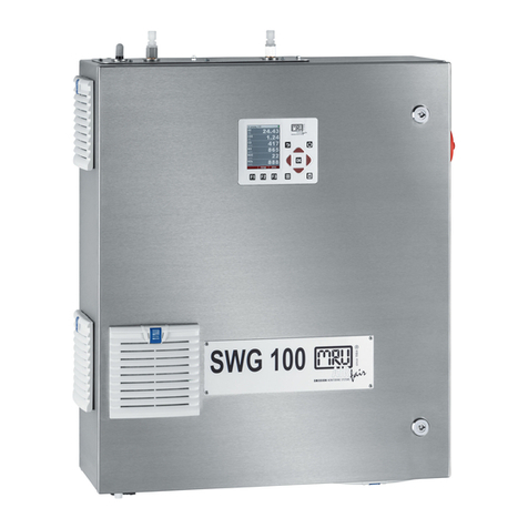
mru SWG100 BIOEX User manual

9512EN-SWG
SWG100
USER MANUAL

USER MANUAL SWG100
MRU GmbH, D-74172 Neckarsulm
2 / 158

USER MANUAL SWG100
MRU GmbH, D-74172 Neckarsulm 3/
158
Content
1. Information for product and safety ....................................................................6
1.1. Safety manual..............................................................................................................6
1.2. Safety precautions......................................................................................................6
1.3. Weather and environmental conditions............................................................8
1.4. General important instructions for theplant operator.................................9
1.5. Packing...........................................................................................................................9
1.6. Return of hazardous waste......................................................................................9
1.7. Return of analyzer......................................................................................................9
1.8. MRU Warranty conditions........................................................................................9
2. Analyser Description.............................................................................................11
2.1. Intendeduse..............................................................................................................11
2.2. Principleof operation............................................................................................11
2.3. Physical characteristic ofthe gas analyzer.....................................................13
3. Scope of supply / mounting positions.............................................................15
4. Installation manual................................................................................................17
4.1. Overview.....................................................................................................................17
4.2. Select measurement point...................................................................................18
4.3. Installation of themountingflange..................................................................20
4.4. Installation of the analyzer...................................................................................22
4.5. Connectionof main powersupply....................................................................23
4.6. I/O modules:Installation and setting...............................................................24
4.7. Installation: Samplegasoutlet (VENT).............................................................26
4.8. Installation: Calibration gas/ zero gas and condensateoutlet...............27
4.9. Installation of the sampling line andprobe...................................................28
5. Operation of the analyzer (HMI) ........................................................................33
5.1. Display and keypad.................................................................................................33
6. Analyzer commissioning manual ......................................................................34
6.1. Check country and language..............................................................................34
6.2. Check date and timeof the instrument..........................................................34
6.3. Configuration of the alarm relays......................................................................35
6.4. Configuration of the Modbus..............................................................................37
7Binding to a process control system: I/O modules .......................................39
7.1. Position of the IOmodule inside theanalyzer..............................................39
7.2. Pin assignment.........................................................................................................40
7.3. Analogoutputs4-20mA.......................................................................................42
7.4. Alarmoutputs...........................................................................................................48
7.5. Analoginputs(4-20mA).......................................................................................53
7.6. Configuration of the external control (Option: IOmodule).....................58
7.7. Mounting and installation of the gas cylinders for the auto calibration
function.....................................................................................................................................65
7.8. Cycle configuration.................................................................................................68
7.9. Administrator PIN code.........................................................................................75
7.10. Power-Onof analyser.............................................................................................75
8. Operating the analyser.........................................................................................76
USER MANUAL SWG100
MRU GmbH, D-74172 Neckarsulm 4/
158
8.1. General process ofthe measurement cycle...................................................76
8.2. Data Storage Menu.................................................................................................79
8.3. Extra menu: Overview............................................................................................83
8.4. Update thefirmware..............................................................................................93
9. Service and maintenance....................................................................................96
9.1. Preparingandinformationaboutthe maintenance...................................96
9.2. Regular maintenance works by the operator................................................96
9.3. Descriptionof the analyser..................................................................................97
9.4. Exchangeof electrochemical sensors............................................................102
10. Maintenance: HD-probe with back purge function ...................................104
10.1. Positions ofthe components ............................................................................105
10.2. Preparations.............................................................................................................106
11. Maintenance: Filter holder................................................................................107
12.Exchange the seals..............................................................................................110
14. Technical specification ......................................................................................112
15. APPENDIX..............................................................................................................115
A. Specification Modbus via RS485 specification ............................................115
15.1. Analyser Status (address 0and some mirroraddresses).........................119
15.2. Analyser System Alarm (address 2 andsome mirror addresses)..........119
15.3. Heated Sampling Line general remarks........................................................120
15.4. General Instructions forthe heated samplinglines..................................122
16. Purchase options of the analyser....................................................................126
16.1. Option: Electric sample gas cooler..................................................................126
16.2. Option: Cabinetheater........................................................................................127
16.3. Option: O2 paramagnetic cell measurement 0-25,00%..........................128
16.4. Option: Multiple sample pointswitching andmonitoring (time sharing)
129
16.5. Option: ExtraIO module with 4 channel4-20 mA.....................................130
16.6. Option: CO electrochemical cell measurement 0-2000ppm/4000ppm
131
16.7. Option: RS485 to Profi-Busconverter.............................................................132
16.8. Option: RS485 to Ethernetconverter .............................................................133
16.9. Option: NDIR-bench 334mmm........................................................................134
16.10. Configuration of the ethernetmodule ......................................................138
16.11. Option: Connection the SWG100 with RS-485 converter to MRU4Win
145
17. Declaration of conformity.................................................................................148
18. Charts .....................................................................................................................149
18.1. Gas flow chart..........................................................................................................149

USER MANUAL SWG100
MRU GmbH, D-74172 Neckarsulm 5/
158
Inspect Shipment for Damage
Carefully inspect the entire shipment for damage in the presence of the shipper’s agent,
removing packaging material if necessary. Note any damage to packaging and/or goods on
Packing List and have it signed by the shipper’s agent prior to accepting the shipment.
Submit damage claim to MRU immediately.
NOTE: Damage claims notreceived by MRU within 3 days of receipt of shipment
will not beaccepted.
The products described in this manual are subject to continuous development and
improvement and it is therefore acknowledged that this manual may contain errors or
omissions. MRU encourages customer feedback and welcomes any comments or
suggestions relating to the product or documentation.
Please forward all comments or suggestions to the Customer Feedback
Department atthe following address:
MRUGmbH
Fuchshalde 8+ 12
74172 Neckarsulm / Obereisesheim
GERMANY
Fon (+49) 71 32 99 62 0 (Reception)
Fon (+49) 71 32 99 62 61 (Service)
Fax (+49) 71 32 99 62 20
Email: [email protected]
Homepage: www.mru.eu
This manual is intended solely as a guide to the use of the product.
MRU shall not beliable for any loss or damagewhatsoever arising from content
e misuse
resulting from the use of this manual.
FOR MORE INFORMATION ABOUT COMPANY MRU PLEASE VISIT OURWEBSITE
www.mru.eu

USER MANUAL SWG100
MRU GmbH, D-74172 Neckarsulm 6/
158
1. Information for product and safety
1.1. Safety manual
All general information and safety precautions of MRU products are listed in the
supplied separate safety manual.
All information and safety precautions for the analyser in the Safety Manual also
apply to the analyser.
Therefore, this manual must be read and observed before the first use of the
instrument.
Instrument-specific safety and warning requirements in this manual are prefixed
before dangerous actions.
1.2. Safety precautions
The used categories of safety precautions are here explained once more.
DANGER
Identifies animmediate, impending hazard that, if
ignored, will result in severe bodily injuriesor death.
WARNING
Identifies animmediate, impending hazard that, if
ignored, may result in severe bodily injuries, material
damage or death.
CAUTION
Identifies a possibly dangerous situation that, if
ignored, may resultin minor injuries.
ATTENTION
Identifies a possibly harmful situation that, if ignored, may
result in damages to the device orits
surroundings.
NOTE
Identifies user tips and other especially important
information.
Thefollowingsafetyproceduresmustbefollowedatalltimes.Theyaresignificant
and essential part of thismanual. Failure to follow safety procedures can result in
the loss of yourwarranty claims.
Gases (landfill gas, bio-methane, coal seam gas etc.) can contain flammable gas
component
CH4
and toxic gas component as well (
H2S
and
CO2
).
Analyzer is continuously sampling a certain volume (approx. 50l/h) of the sample
gas and is ventingit to ambient air.
For this reason, there are two aspects which must beconsidered:

USER MANUAL SWG100
MRU GmbH, D-74172 Neckarsulm 7/
158
Toxicity danger of sample gas
WARNING
Toxic gas
Sample gas can containtoxic substances, which areharmful for
health and can even cause death.
It is the responsibility ofanalyser user to ensure that person is skilled and
trained in safety aspects of gases being analysed and procedures to
follow while usingthis instrument.
Local regulations for possible exposure to toxic gases must be known
and obeyed by theuser of the analyser
Using a personal gas detector inside the plant is highly recommended
since
H2S
in higher (verydangerous) concentration cannot bedetected
by humannose. Only small concentrations around few ppm can be
detected by humannose
CO2
gas is heavier than airand thereforeoperator shall avoid working at
underground levels. Beware of that
CO2
isalso odorless!
It is not allowed to use theanalyser in confined space or rooms
without forcedventilation.
Sample gas exiting the analyser will flow into the ambient air and only
outdooruse
or forced ventilation rooms are suitable for using the analyser.
Flammable gas
WARNING
Flammable gas
Gas can containflammable gas components.
Regarding flammablegases (e.g.
CH4
methane)andoperating-instrumentsinthe
hazardous areas, the user must also be able to recognize the area classification
and be aware of using the instrument there. This area classification is country
specific, please observe and adhere to it.
Stationary analysers are allowed to bemounted in hazardous area zone
2 only if they have the certificateof compliance. These instruments shall
never be locatedin confined placesor rooms without forced ventilation.
Only trained personnel should carry out installation of stationary instrument
and/or maintenance, service and repair. Opening the stationary analyser cabinet
can expose personnel to injuries andshocks from electrical voltage!

USER MANUAL SWG100
MRU GmbH, D-74172 Neckarsulm 8/
158
Acid condensate
WARNING
Acid substances
Moisture or condensate, being pumped out of the condensate
outlet port can be slightly acidic.
•In case ofskin contactIMMEDIATELY: clean affected parts
of the body.
•Avoid getting liquid ineyes.
Please carefully clean all parts that come into contact with the
condensate.
NOTE
Condensate
The SWG100 analyser is designed for sampling with condensate of
max.14ml/min.
If the sample will be very wet (high condensate of more than
14ml/min),then toprotecttheSWG100analyser pleaseconsider
special precautions to remove the condensate.
If you do not have your own feasible solution for this topic, please
ask MRU.
1.3. Weather and environmental conditions
The SWG100analyser is designed for ambient temperatures of +5°C to +45°C
(without cabinet heater) resp. -10°C to +45°C (with cabinet heater).
The analyser isdesigned for indoor mounting.In case of outdoor mountingit is
important that the analyser is sufficiently protected againstrain, sun and wind.
In case of outdoor mounting underextreme environmental conditions like high
humidity, salty sea air, etc.further protective measures are necessary. These
should be clarified with the manufacturer (MRU).
Any additional protective measures for outdoor mounting have to be provided
by the plantoperator. Themanufacturer (MRU) consults the plant operator in
choosing appropriate protective measures.

USER MANUAL SWG100
MRU GmbH, D-74172 Neckarsulm 9/
158
1.4. General important instructions for the plant operator
To guarantee continuous operation of the SWG100 analyser, the functions,
processes, and operation of the analyser have to be monitored regularly by the
plantoperator especiallyincaseofanyinitialinstallation.Thus,itwillbepossible
totakesuitablemeasuresto improvetheavailabilityand life timeoftheanalyser.
As the plant operator gains more experience concerning the maintenance
requirementsof theanalyser,themonitoringfrequencymay be reducedtomore
extendedperiodsof time.
NOTE
In case of not intended use the guarantee will void. Regular
controls, inspections and the exchange from polluted and
exhausted filters by the operator are also an important part of the
not determined use - see chapter
for regularmaintenancework.
1.5. Packing
Packing regulationof 12.07.1991
IfyourlocalwastefacilitydoesnotacceptMRUpackingmaterialsfordisposal,you
may return ittoMRU orour localsales representative. Packingmaterials returned
to MRUmust be returnedprepaid.
1.6. Return of hazardous waste
Waste Disposal/Returns/Warranty -
MRU GmbH is required to accept the return of hazardous waste such as electro-
chemical sensors that cannot be disposed of locally. Hazardous waste must be
returned to MRU prepaid.
1.7. Return of analyzer
MRU GmbH is required to accept the return, for proper disposal, of all analyzers
delivered after 13th ofAugust2005. Analyzers mustbe returned toMRU prepaid.
1.8. MRU Warranty conditions
The SWG100warranty is 12 months.
1. The warrantyon spare parts is 6months.
2. The term of thewarranty conditions starts as of the invoice date.
3. The warrantyis void under thefollowing conditions:
•Improperuse.
•Improperapplication.
•Impropermounting.
•Deliberate or negligent destructions.
•Externalinfluencelikedroping,impact,solvents,acids,gases,ortransport
damages. This includes damage, which is caused by exposure to high
pollution and/or moisture(condensate)in the gas path.
4. As well excluded from the guarantee conditions are typical consumable- and
spare parts.
5. Use of original MRU consumable parts and sensors is required to maintain the
warranty.

USER MANUAL SWG100
MRU GmbH, D-74172 Neckarsulm 10/
158
6. Removalof tampering of the serial number type plate will void the warranty.
7. The service of a guarantee conditions will not enlarge the guarantee time.
Demands becauseof consequential damages are excluded.
8. MRU isnot responsible for the transport costs for the warranty or replacement.
9.MRUreservestheright,todetermineindividualconditionsorexceptions.These
will be separately communicated.
MRU GmbH
01.09.2014

USER MANUAL SWG100
MRU GmbH, D-74172 Neckarsulm 11/
158
2. Analyser Description
•Read and observe the separately supplied Safety manual.
•This manual enables you to understand and safely operate this
MRU Analyzer.
•Please read this manual with great vigilant.
•Get familiar with the product before using it.
•This analyser may only be operated by competent personnel and
for its intended use.
•The analyser may only be used by qualified personnel for the
intended use.
•Please pay special attention to all safety directions and warnings to
prevent personal injuries and damaging of the product.
•We cannot be held responsible for any injuries and/or damages
that occur by not following the instructions in this manual.
•Always keep the manual near you when working with the analyser,
to be able to read instructions as needed. Please ensure to hand
over all documents to when handing the analyser over to others.
•Hand over all documents when passing on the analyser to third
parties.
2.1. Intended use
The instrument is intended for analysing the composition of biogases /
landfill gases and determine the concentration of several components
like CH4, CO2, O2andH2S. The instrument may optionally be equipped to
monitor several sites in time sharing technique (cyclical one by one
sampling).
In particular, the instrument is not foreseen to serve as a gas detector or
safety device.
In case of unintended use, the warranty is void. Regular controls,
inspections and the replacement of polluted and exhausted filters by the
operator are also an important part of proper use. See chapter
regular maintenance work.
2.2. Principle of operation
•Sample gas from one or more sampling points is fed into the
analyser by dedicated ports. Internally mounted electric valves
select one point at a time to feed sample gas to the analysis unit.
•The instrument is equipped with a non-dispersive infrared (NDIR)
bench for analysis of
CO2
and
CH4
. Two separate infrared
detectors for each
CO2
and
CH4
are included, each operating with
a different optical path length and stabilized by referring to a
reference detector. The IR source is a highly efficient and stable IR
emitter, pulsed at a frequency of several Hertz. By design NDIR
technique offers good stability and selectivity together with long

USER MANUAL SWG100
MRU GmbH, D-74172 Neckarsulm 12/
158
lifetime of sensor (only limited by corrosion or dust, which can be
prevented or removed by regular servicing the instrument).
•The instrument is optionally equipped with several electro-
chemical sensors ECS to detect gas components like oxygen
O2
or
H2S
. Those sensors offer a reliable and effective way to detect the
target gases. They are typically of limited lifetime (several years)
but may be easily replaced once the end-of-life is reached.
•In regular time intervals the instrument automatically switches to
purge the sensors with fresh (ambient) air for re-adjust the zero
point.
Picture above: Sample gas flow diagram (Picture is an example. It only shows the
principle).

USER MANUAL SWG100
MRU GmbH, D-74172 Neckarsulm 13/
158
2.3. Physical characteristic of the gas analyzer
Top view
Front view
Reference
1Sample gas inlet for f
2Cabinetlock
3Display and operation
4Cabinet mounting
5

USER MANUAL SWG100
MRU GmbH, D-74172 Neckarsulm 14/
158
Right side Left side
Bottom view
Reference:
1. Fan filter 5. Cable glandfor power supply
2. Calibration gasinlet (G1/8 inner thread) 6. Power switch
3. Zero gasinlet (G1/8 inner thread) 7. Cable glandfor IO module
4. Condensate outlet (G1/8 inner thread)

USER MANUAL SWG100
MRU GmbH, D-74172 Neckarsulm 15/
158
3. Scope of supply / mounting positions
Your analyzer is delivered in a carton box and is protected with special edge
protectors. Please dopreserve the packingof your analyzer, forpossible back
shipment.
Inside the attachments box are different fittings:
Following content are on the SD-Card:
Number
Image
Name
Description
1
Sample gas
inlet-with
restriction
Tube DN6/4mm-G1/8 outer thread
2Vent outlet Tube DN12/10mm-G1/4 outer thread
3
Calibration
gas inlet-with
restriction
Tube DN6/mm-G1/8 outer thread
4
Zero gas inlet-
filter
Filter-G1/8 outer thread
5
Condensate
outlet
Tube DN6/4mm outer thread
5Cabinet key Key for cabinet
6Copper seal
Copper seal for sample gas inlet and
calibration gas inlet
7SD-card 4GB-SD card

USER MANUAL SWG100
MRU GmbH, D-74172 Neckarsulm 16/
158
•
Ethernet-Converter manual
•
Profibus-Convertermanual
•
GSD-Files for profibus-converter
•
SWG100-Bio manual(EN/DE)
•
SWG100-Bio ModBus/Profibus specification (EN/DE)
The SD-card canbe foundin the SD-card slot in the device (see sketchbelow).

USER MANUAL SWG100
MRU GmbH, D-74172 Neckarsulm 17/
158
4. Installation manual
4.1. Overview
This manual explainshow to install theanalyzer mechanically and electrically.

USER MANUAL SWG100
MRU GmbH, D-74172 Neckarsulm 18/
158
The installer must correctly assemble these parts during installation. The
followingdiagramshowsthesequenceinwhichtheinstallationshould becarried
out:
Preparationofthemeasurementpoints
Analyzer mounting
Power supply
Connect IO module to control room
Connectsamplegas outlet
Connect adjustment,zero gas and condensate outlet.
Mounting probe and heated sampling line
Mounting pressureline for purge function (Optional)
4.2. Select measurement point
The measuring point should be in an area where the flow no longer has
any particular turbulence. Thatis:
•Not directly before orafter apipe elbow. The measuringpoint mustbe at
least 3 times the chimney diameter from a bend.
•The probe may bemounted both horizontally and vertically.
•Theopeningshouldhaveaccesstothecoreflow.Thisisusuallythecentre
of the pipe.

USER MANUAL SWG100
MRU GmbH, D-74172 Neckarsulm 19/
158
•For installations on a metal pipe,make sure thatthe wall thickness can
support theweight of the probe. For this purpose the mounting flange
is welded to the pipe.
•For installation on a brick fireplace, it is advantageous to screw a steel
plate with the correct hole diameter to the brickfireplace.
Above 3 timesof diameter
Over 3 timesof diameter
Core flow

USER MANUAL SWG100
MRU GmbH, D-74172 Neckarsulm 20/
158
4.3. Installation of the mounting flange
The mountingflange is notscope of supply.
The sketch below shows the necessary dimensions of the mounting flange. The
mounting flange has the same dimensions as a DN65/PN6flange (dimensions as
DIN2573).A steelpipeisweldedonto theflange.Thelengthof thistubedepends
on the probelength and the insulation thickness.
A: The distance should be short as possible. It must have enough distance to
install the mounting flange correctly. The planned insulation must also be taken
into account.
B: this distance takes the thickness of the insulation into account. This is the
minimal length of thepipe.
C:ThedistanceCtakesintoaccounthowfarthepipegoesintothechimney.This
is necessaryif the probe tube is larger than 1500mm to increase stability.
The mounting flange is the basic of the mechanical installation. For a correct
installationit is necessary to take some rulesinto account:
1.
Installation side:
The installation location must be safe and easily accessible. The probe
should be installed in a location where the flow is already pronounced.
Therefore, the installation location should be at least 3 times the
diameter, from the last elbow.
2.
Installation situation
The devicecan be mounted verticaland horizontal.
3.
Orientation
Itisadvantageousifthemountingflangeisinclinedatleast2°againstthe
flow, so that any moisture can drain off. The mounting flange should not
be inclined upwards. The mounting flange should also be straight in the
horizontaldirection.
Other manuals for SWG100 BIOEX
2
Table of contents
Other mru Measuring Instrument manuals

mru
mru SYNGAS VARIOluxx User manual

mru
mru VARIOluxx User manual

mru
mru AIR fair OPTIMA 7 User manual

mru
mru AirFair OPTIMA 7 NDIR User manual

mru
mru AIR fair SWG 100 biogas User manual

mru
mru DELTAsmart User manual

mru
mru DELTAsmart FFZ User manual

mru
mru Optima 7 User manual

mru
mru DM9600 User manual

mru
mru DELTAsmart User manual
Popular Measuring Instrument manuals by other brands

HTA Instrumentation
HTA Instrumentation C-223 instruction manual

LEGRAND
LEGRAND 0 435 01 Instructions for installation and use

MARTINDALE
MARTINDALE TEK100 instruction manual

PCB Piezotronics
PCB Piezotronics IMI SENSORS 607A11/075AC Installation and operating manual

MRC
MRC DI-900 Operation manual

Ditel
Ditel ALPHA-D user manual