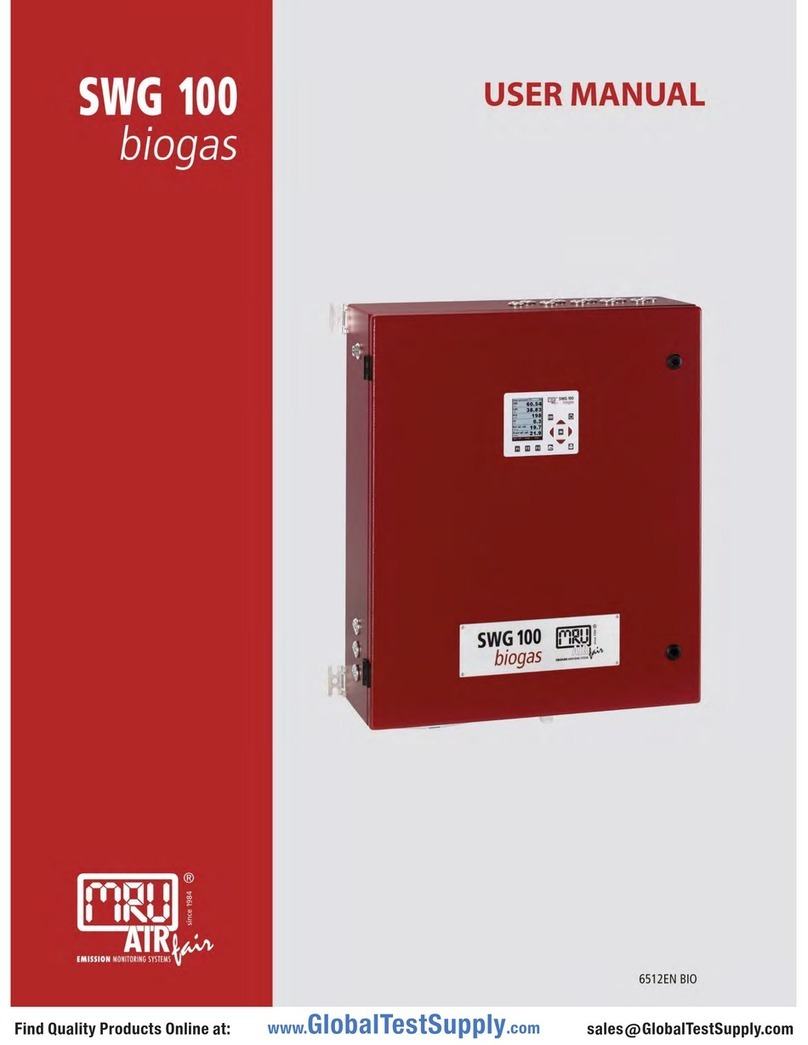
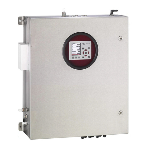
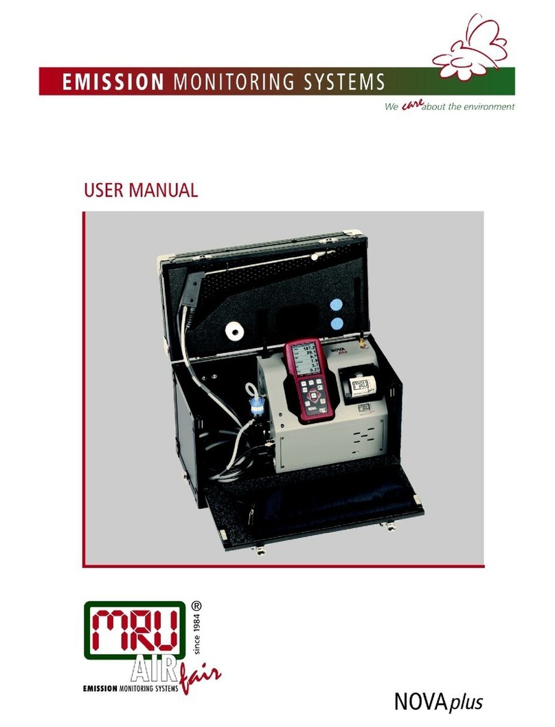
mru SWG 100 SYNGAS User manual

SWG 100 SYNGAS
USER MANUAL

Manufacturer:
Legal notices / Intellectual property rights comments
Original user manual
© 2021by MRU
No part of this manual my be published in any form (print, fotocopy, electronic media or
any other publication form) without a written approval by the publisher.
All user trade marks and name mark descriptions, even those which are not marked as
such, are properties of the respective owners.
Edition: 2021-11.05,V1.00.EN

USER MANUAL SWG
Page 3of129
Content
1. Information for product and safety............................................................................ 5
1.1. Safety manual ...................................................................................................... 5
1.2. Safety precautions................................................................................................ 5
1.3. Weather and environmental conditions ................................................................ 7
1.4. General important instructions for the plant operator ........................................... 7
1.5. Packing................................................................................................................. 8
1.6. Return of hazardous waste................................................................................... 8
1.7. Return of analyser................................................................................................ 8
1.8. MRU Warranty conditions..................................................................................... 8
2. Analyser Description 0004 ......................................................................................... 9
2.1. Intended use......................................................................................................... 9
2.2. Principle of operation............................................................................................ 9
2.3. Packing dimensions and designations 0005..................................................... 11
2.4. SD-Card: Position and content........................................................................... 14
1. Safety concept of syngas analyser 0016............................................................... 15
2.5. Fan monitoring ................................................................................................... 15
2.6. Internal LEL sensor ............................................................................................ 15
2.7. Gas reducing unit ............................................................................................... 15
2.8. External switching unit........................................................................................ 15
3. Installation manual 0006.......................................................................................... 16
3.1. Overview ............................................................................................................ 16
3.2. Select measurement point.................................................................................. 18
3.3. Installation of the analyzer.................................................................................. 18
3.4. Installation of pressure reducer unit ................................................................... 20
3.5. Connection of main power supply ...................................................................... 22
3.6. I/O modules: Installation and setting .................................................................. 25
3.7. Installation: Calibration gas / zero gas and condensate outlet ........................... 27
4. Operation of the analyser (HMI) 0007..................... Fehler! Textmarke nicht definiert.
4.1. Display and keypad........................................Fehler! Textmarke nicht definiert.
5. Binding to a process control system: I/O modules 0008...................................... 33
5.1. Position of the IO module inside the analyzer .................................................... 33
5.2. Pin assignment................................................................................................... 34
5.3. Analog outputs 4-20 mA..................................................................................... 36
5.4. Alarm outputs ..................................................................................................... 42
5.5. Analog inputs (4-20 mA)..................................................................................... 47
5.6. Configuration of the external control (Option: IO module) .................................. 52
1. Analyser commissioning manual0009................................................................... 59
5.7. Power up the analyser........................................................................................ 59
5.8. Checking list for commissioning ......................................................................... 60
5.9. Check country and language.............................................................................. 60
5.10. Check date and time of the instrument............................................................... 61
5.11. Configuration of the alarm relays........................................................................ 62
5.12. Configuration of the Modbus .............................................................................. 65
6. Cycle configuration 0010......................................................................................... 69
6.1. Path and default setting...................................................................................... 69
6.2. General information............................................................................................ 69

USER MANUAL SWG
Page 4of129
6.3. Auto configuration...............................................................................................69
6.4. Insert a phase .....................................................................................................70
6.5. Configuration of the phase details ......................................................................70
6.6. Example for a measurement cycle configuration ................................................73
7. Operating the analyser 0013....................................................................................76
7.1. General process of the measurement cycle........................................................76
7.2. Data Storage Menu.............................................................................................79
7.3. Update the firmware............................................................................................84
8. Service and maintenance 0018................................................................................88
8.1. Preparing and information about the maintenance.......................................88
8.2. Regular maintenance works by the operator .................................................88
8.3. Description of the analyser..............................................................................89
8.4. Exchange the condensate pump head unit....................................................97
9. Specification Modbus via RS485 specification 0016...........................................100
9.1. General information ..........................................................................................100
9.2. Analyser Status (address 0 and some mirror addresses) .................................104
9.3. Analyser System Alarm (address 2 and some mirror addresses).....................104
10. Adjustment: NDIR-bench (MGB-Module).......................................................105
11. Technical specification ...........................................................................................108
Appendix...........................................................................................................................108
11.1. Installation: HD probe with heated sampling line ..............................................111
11.2. Maintenance: HD-probe with back purge function ............................................115
11.3. Maintenance: Filter holder ................................................................................118
12.1. General Instructions for the heated sampling lines...........................................122

USER MANUAL SWG
1. Information for product and safety
1.1. Safety manual
All general information and safety precautions of MRU products are listedin the
supplied separate safety manual.
All information and safety precautions for the analyser in the Safety Manualalso
apply to the analyser.
Therefore, this manual must be read and observed before the first useof the
instrument.
Instrument-specific safetyand warning requirements inthis manual are prefixed
before dangerous actions.
1.2. Safety precautions
The used categories of safety precautions are here explained oncemore.
•DANGER
Identifies animmediate,impending hazard that, if
ignored, will result in severe bodily injuries or death.
•WARNING
Identifies animmediate,impending hazard that, if
ignored, may resultin severe bodilyinjuries, material
damage or death.
•CAUTION
Identifies a possibly dangerous situation that, if
ignored, may resultin minor injuries.
ATTENTION
Identifies a possibly harmful situation that, if ignored, may
result in damages to the deviceor its
surroundings.
NOTE
Identifies user tips and other especially important
information.
The following safetyproceduresmust be followed atall times. They aresignificant
and essential partof this manual.Failure to follow safety procedures can result in
the loss of yourwarranty claims.
Gases (landfill gas, bio-methane, coal seamgas etc.) can contain flammable gas
component
CH4
and toxic gas componentas well(
H2S
and
CO2
).
Analyzer is continuously sampling a certain volume (approx. 50l/h) of the sample
gas and is ventingit to ambient air.
For this reason, there are two aspects whichmust beconsidered:

USER MANUAL SWG
Toxicity danger of sample gas
•WARNING
Toxis gas
Sample gas can be contain toxic substances, whichare
harmful for health and caneven cause death.
It is the responsibility of analyser user to ensure that person is skilled and
trained in safety aspects of gases being analysed and procedures to follow
while using this instrument.
Local regulations for possible exposureto toxic gases mustbe known and
obeyed by the userof the analyser
Using a personal gasdetector inside the plantis highly recommended since
H2S in higher(very dangerous) concentration cannot be detected by
human nose. Onlysmall concentrations around fewppm can be detected
by human nose
CO2 gas is heavier than air and thereforeoperator shall avoid working at
underground levels. Beware of that CO2is also odorless!
It is not allowed to use the analyser in confined space or rooms
without forcedventilation.
Sample gas exiting the analyser will flowinto the ambient air and only
outdoor use or forced ventilation rooms aresuitable for using theanalyser.
Flammable gas
•WARNING
Flammable gas
Gas can contain flammable gas components.
Regarding flammable gases (e.g.
CH4
methane) and operating-instruments in the
hazardous areas, the usermust also be able to recognize the area classification and
be aware of using the instrument there. This area classification is country specific,
please observe and adhere to it.
Stationary analysers are allowed to be mounted in hazardous areazone 2
only if they have the certificate of compliance.Theseinstruments shall
never be locatedin confined placesor rooms without forcedventilation.
Only trainedpersonnel should carryout installation of stationaryinstrument and/or
maintenance, service and repair. Openingthe stationary analyser cabinet can
expose personnel to injuries and shocks from electrical voltage!

USER MANUAL SWG
Acid condensate
•WARNING
Acid substances
Moisture or condensate, being pumpedout of the
condensate outletport can be slightly acidid.
►In case of skin contact immediately clean affected
parts of the body.
►Avoid getting liquid in eyes.
Please carefully clean all parts that come into contact
with the condensate.
NOTE
Condensate
The SWG100 analyser is designedfor sampling with
condensate of max. 14 ml/min.
►If the sample will be very wet (high condensate of
more than 14 ml/min.), then
►To protect the SWG100 analyser please consider
special precautions to remove the condensate.
If you do not have your own feasible solution for this
topic, please ask MRU.
1.3. Weather and environmental conditions
The SWG100 analyser is designed for ambienttemperatures of +5°C to +45°C
(without cabinet heater) resp. -10°C to +45°C(with cabinet heater).
The analyser isdesigned for indoormounting. In case ofoutdoor mounting it is
important that the analyser is sufficiently protected against rain, sun and wind. In
case of outdoor mounting underextreme environmental conditionslike high
humidity, salty sea air, etc.further protective measures are necessary. These should
be clarified with the manufacturer (MRU).
Any additional protective measures for outdoor mounting have to beprovidedby
the plant operator. The manufacturer (MRU) consultsthe plant operator in
choosing appropriate protective measures.
1.4. General important instructions for the plant operator
To guarantee continuousoperation of the SWG100 analyser, the functions,
processes, and operation of theanalyser have to bemonitored regularly bythe
plant operator especially incase of any initial installation. Thus, it will be
possible to take suitable measures toimprove the availability and life time of the
analyser.

USER MANUAL SWG
Page 8of129
As the plantoperator gainsmore experienceconcerning the maintenance
requirements of the analyser, the monitoring frequency may be reduced to
more extended periods oftime.
NOTE
In case of not intended use the guarantee will void.Regular
controls, inspections and the exchange frompolluted and
exhausted filtersby the operator are also an important part
- see chapter
1.5. Packing
Packing regulationof 12.07.1991
If your local waste facilitydoes not acceptMRU packing materials for disposal,
you may returnit to MRU or our localsales representative. Packing materials
returned toMRU must bereturned prepaid.
1.6. Return of hazardous waste
Waste Disposal/Returns/Warranty -
MRU GmbHis required to accept the returnof hazardouswaste suchas electro-
chemical sensors that cannot bedisposed of locally. Hazardouswaste mustbe
returned to MRU prepaid.
1.7. Return of analyser
MRU GmbHis required to acceptthe return, for proper disposal, of all analysers
delivered after13th of August 2005. Analyzersmustbe returned to MRU
prepaid.
1.8. MRU Warranty conditions
The SWG100 warranty is 12 months.
1. The warrantyon spare parts is 6 months.
2. The term of thewarranty conditions starts as of the invoice date.
3. The warrantyis void under the following conditions:
•Improperuse.
•Improperapplication.
•Impropermounting.
•Deliberate or negligentdestructions.
•Externalinfluencelikedroping,impact,solvents,acids,gases,ortransport
damages. This includes damage, which is caused by exposure to high
pollution and/or moisture (condensate)in the gas path.
4. As well excluded from the guarantee conditions are typical consumable- and
spare parts.
5. Use of original MRU consumable parts and sensorsis required to maintain the
warranty.
6. Removalof tamperingof the serial number type plate will void thewarranty.
7. The service of a guarantee conditionswill not enlarge the guarantee time.
Demands becauseof consequential damages are excluded.
8. MRU is notresponsible for the transport costs for the warrantyor
replacement.
9. MRU reserves the right, to determineindividual conditions or exceptions.
These will beseparately communicated.

USER MANUAL SWG
Page 9of129
MRU GmbH
01.09.2014
2. Analyser Description 0004
•Read and observe the separately supplied Safety manual.
•This manual enablesyou to understand and safely operate thisMRU
Analyzer.
•Please read this manualwith great vigilant.
•Get familiarwith the product before usingit.
•This analyser mayonly beoperated by competent personnel and forits
intendeduse.
•The analyser mayonly be used by qualified personnel for theintended
use.
•Please pay special attention to all safety directionsand warnings to
prevent personal injuries and damaging of the product.
•We cannot beheld responsible forany injuriesand/or damages that
occur by not following the instructions in thismanual.
•Always keep themanual near youwhen working with the analyser, to be
able to readinstructions as needed.Please ensure tohand over all
documents to when handing the analyser over to others.
•Hand over alldocumentswhen passingon the analyser to third parties.
2.1. Intended use
The instrumentis intended for analysing the compositionof several gases. The
list shows theanalyser components, which can be determined by theanalyser.
•CO
•CO2
•CH4
•H2
•O2
The analyzer comes with asampling probe for the installation at the
measurementpoint anda samplingline system.
In particular, theinstrument is not foreseento serve as a gas detector or safety
device.
In case of unintended use,the warranty is void. Regular controls,inspections and
the replacementof polluted and exhausted filters by the operator are also an
important part of proper use.
work.
2.2. Principle of operation
•Gas is suckedfrom the measuring point, throughthe probe,via a
PTFE hoseinto thedevice.
•The sample gas isdried to a dew point of 5°C by a gas cooler.
•Further internalfiltering and an acidseparator ensure that the
sample gas istreated before it enters theNDIR measurement
technology.
•The instrumentis equipped with anon-dispersiveinfrared (NDIR)
bench for different analysis. Separate infrareddetectors foreach gas

USER MANUAL SWG
Page 10of 129
are included, each operating with a differentoptical path length and
stabilized by referring to areference detector. The IRsource is a
highly efficient and stableIR emitter, pulsedat a frequencyof several
Hertz. By design NDIR technique offersgood stability and selectivity
together with longlifetime of sensor (onlylimited by corrosion or
dust, which can be prevented or removed by regular servicing the
instrument).
•The instrumentis optionally equippedwith severalelectro-chemical
sensors ECS todetect gascomponents like oxygen
O2
.Thosesensors
offer a reliableand effective way to detect the targetgases. They are
typically of limited lifetime(several years) but may be easily replaced
once the end-of-lifeisreached.
•In regular timeintervals the instrument automatically switches to
purge the sensors with fresh (ambient) air forre-adjust the zero point.
Picture above: Sample gasflow diagram (Picture is an example. It only shows the
principle).

USER MANUAL SWG
Page 11of 129
2.3. Packing dimensions and designations 0005
Packing dimensions:
LxWxH [mm]= 700x 800 x 180
Reference:
1
Fan filter
2
Calibration gas inlet
3
Zero gas inlet
4
Condensate outlet
5
Cable gland for power supply
6
Filter unit
7
Cable gland for IO modul
8
Sample gas inlet G1/8 inner thread
9
Sample gas inlet for heated sampling line
10
Sample gas outlet (VENT) G1/4
inner thread
1
1
1
1
4
4
10
3
2
5

USER MANUAL SWG
Page 12of 129
11
H3PO4-inlet G1/8 inner thread

USER MANUAL SWG
Page 13of 129
Connection options at inputs and outputs 0012
#
Connection system
Position
1
G1/8 inner thread
2 / 3 / 4 /9
2
G1/4 inner thread
10
Fitting list (scope of supply)
#
Position
Description
Article number
1
1 / 2 / 3 / 4/ 9
Fitting G1/8 inner thread to DN 6/4 hose
55764
2
10
Fitting G1/4 inner thread to DN 6/8 hose
55110
3
1 / 2 / 3 / 4/ 9
Cooperseal
4
SD-Card
5
1
Filtermat
6
9
Fitting for heated sampling line (read installed
at the top, if option is available).
1
2
3
4
5
6

USER MANUAL SWG
Page 14of 129
2.4. SD-Card: Position and content
Following content are on the SD-Card:
•Ethernet-Converter manual
•Profibus-Convertermanual
•GSD-Files for profibus-converter
•Analyser- manual(EN/DE)
•Analyser ModBus/Profibus specification (EN/DE)
The SD-card canbe foundin the SD-card slot in the device (see sketch below).

USER MANUAL SWG
Page 15of 129
1. Safety concept of syngas analyser 0016
•WARNING
This device isnot suitable for usein explosiveareas. It does
not have ATEXor comparable approvals.
The Syngas instrument was designed to measure the qualityof useful gases.
Since these gases areoften presentin explosive concentrations, the instrument
has some safety measureswhich are explainedin this chapter. Thedevice has
the following safety concepts:
•Fan monitoring, for permanent dilution.
•Internal LEL sensor, to monitor the interior of the housing.
•Gas reduction nozzles, to reduce the incoming gas flow inside
the lines.
•External switching unit to switch on the analyzer in a safe
environment.
2.5. Fan monitoring
The analyserhas amonitored fan, which isintended to guaranteethat sufficient
ambient air always flows throughthe housing. Thisprevents an explosive
atmosphere from building upinside thehousing. The volume flow of the fan
must be atleast 10l/s.
If this volume flow is not reached, a system alarm appears. If the erroris not
corrected, the device switchesitself off.
2.6. Internal LEL sensor
The internal LELsensoris an unit, whichmonitored the entire inner housing. Ifa
certain gasconcentrationis exceeded a system alarm appears. If the error isnot
corrected, the device switchesitself off.
2.7. Gas reducing unit
The gas flow is reduced bya reducingunit. If there should be aleak in thegas
paths, this guarantees that only a defined quantity of gas can escape into the
housing. Fanmonitoring guaranteesthat, in theeventof such afault, the gas
quantity is diluted to suchan extent that no explosive atmospherecan arise.
2.8. External switching unit
The external switchingunit isdesigned to allow theunit to be switched on from
a safe distance during commissioning or start-up, following a system alarm.

USER MANUAL SWG
Page 16of 129
3. Installation manual 0006
3.1. Overview
This manual explainshow to install the analyzermechanically and electrically.
6
1
2
3
4
6
6
5

USER MANUAL SWG
Page 17of 129
The installer must correctly assemble these parts during installation. The
following diagram shows the sequencein which theinstallation should be
carriedout:
Preparation of the measurement points (see 3.2)
Analyzer mounting (see 3.3)
Power supply (see 3.5)
Connect IO module to control room (see 3.6)
Connect sample gas inlet
Connect zero gas outlet, adjustment gas inlet and condensate outlet.

USER MANUAL SWG
Page 18of 129
3.2. Select measurement point
The measuringpoint should be in an areawhere the flow nolonger hasany
particular turbulence. That is:
•Not directly before or after a pipe elbow. The measuring point
must be at least 3 times the chimney diameter from a bend.
•The probe may be mounted both horizontally and vertically.
•The opening should have access to the core flow. This is usually
the centre of the pipe.
•For installations on a metal pipe, make sure that the wall
thickness can support the weight of the probe. For this purpose
the mounting flange is welded to the pipe.
•For installation on a brick fireplace, it is advantageous to screw
a steel plate with the correct hole diameter to the brick
fireplace.
3.3. Installation of the analyzer
The analyzeris equippedwith adapters for the wallmounting. Thedimensions
for the wall mounting areshown in picture below.
Above 3 timesof diameter
Over 3 timesof diameter
Core flow

USER MANUAL SWG
Page 19of 129
Picture 1: Dimensions for the wall mounting.
A
Min. 500 mm
C
Min. 300mm
B
Min. 300 mm
D
Min. 300 mm
•CAUTION
Only operate the analyzer in an upright position!
Only power the device up after it is correctly mounted!
General installation rules
•Mount thedevice ona solid wallor steel rack.
•Be sure, that the air circulation is not obstructed.
•Let enough room for the tubing or piping.
For outdoor installation
Ensure that the analyzer is mounted ona rain and sun protected place (weather
shade).
For indoor installation:
Ensure that the analyzeris installedon a dry and clean place.Be sure thatthe
room is permanently vented withfresh air.
Connect the VENT gas-outlet of the device to ambientby using adequate tube
with min Ø8mm ID.

USER MANUAL SWG
Page 20of 129
3.4. Installation of pressure reducer unit
•DANGER
Explosion hazard
Do not operate the analyser without pressure
reducer unit.
•DANGER
Explosion hazard
The measuring point must not have an
overpressure of 150 mbar.
•WARNING
As part of the safety concept, a reducing unit must be
installed on each Autocal inlet.
•WARNING
As part of the safety concept, a reducing unit must be
installed oneach sample gas inlet.
NOTE
The copper seal of the nozzle is intended only for
single use.
NOTE
Use PTFE strips to tighten the fitting inside the thread!
NOTE
The pressure reducer unit is equipped with a PTFE
DN4/6 fitting. Use a 1/8G outer thread fitting for using
another fitting.
For safety reasons, the gas inlet and the autocalibration inlet must be equipped
with a pressure reducing unit. This fitting preventsthe gas flow from being
limited in the event of a pipe leak inthe unit.The ventilation ofthe unit prevents
the creation of an explosive atmosphere. This is only guaranteed if the
overpressure at the measuring pointdoes not exceed 150 mbar.
The sketch below shows how thepressurereducer unit isbuilt.
Table of contents
Other mru Measuring Instrument manuals