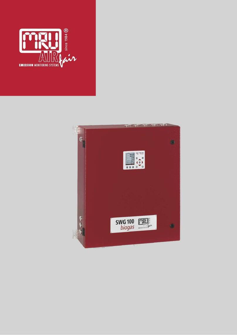
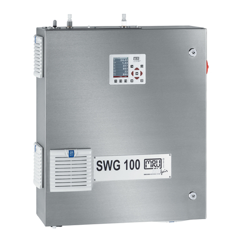
MRU GmbH SWG 100 User Manual
Page 3of 137
Content
1. General Information..........................................................................................................6
1.1. Weather and environmental conditions......................................................................6
1.2. Installation instructions...............................................................................................6
1.3. General important instructions for the plant operator.................................................6
1.4. Important information about the user’s operation manual..........................................7
1.5. Safety Information......................................................................................................7
1.6. Packing......................................................................................................................9
1.7. Return of hazardous waste........................................................................................9
1.8. Return of analyzer......................................................................................................9
1.9. MRU Warranty conditions..........................................................................................9
2. Analyzer Description......................................................................................................11
2.1. Intended use............................................................................................................11
2.2. Type plate................................................................................................................11
2.3. Possible applications and analyzer options .............................................................12
2.4. Principle of operation...............................................................................................12
2.5. Special functions of the analyzer.............................................................................14
2.6. Physical characteristic of the gas analyzer..............................................................15
3. Scope of supply and delivery........................................................................................17
4. SD-card content..............................................................................................................18
5. Installation manual.........................................................................................................19
5.1. Overview..................................................................................................................19
5.2. Installation of the analyzer.......................................................................................20
5.3. Connection of mainpower supply............................................................................22
5.4. I/O modules: Installation and setting........................................................................23
6. Operation of the analyzer (HMI).....................................................................................25
6.1. Display and keypad..................................................................................................25
...........................................................................26
7.1. Check country and language...................................................................................26
7.2. Check date and timeof the instrument....................................................................26
7.3. Configuration of the alarm relays.............................................................................27
7.4. Configuration of the Modbus....................................................................................29
8Binding to a process control system: I/O modules.....................................................31
8.1. Position of the IO module inside the analyzer..........................................................31
8.2. Pin assignment........................................................................................................32
8.3. Analog outputs 4-20 mA ..........................................................................................34
8.4. Alarm outputs...........................................................................................................40
8.5. Analog inputs (4-20 mA)..........................................................................................45
8.6. Configuration of the external control (Option: IO module)........................................50
8.7. Mounting and installation of the gas cylinders for the auto calibrationfunction .......56
8.8. Cycle configuration ..................................................................................................59
8.9. Administrator PIN code............................................................................................65
8.10. Power-On of analyzer..............................................................................................65
............................................................................................. 66
9.1. General process of the measurement cycle.............................................................66
9.2. Data Storage Menu..................................................................................................69
9.3. Extra menu: Overview..............................................................................................73
9.4. Update the firmware.................................................................................................82
www. .com information@itm.com1.800.561.8187
