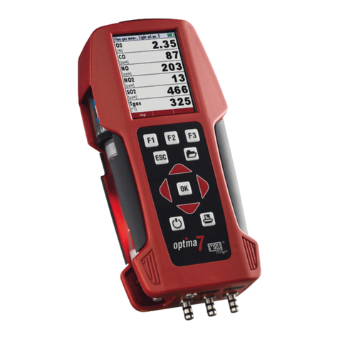
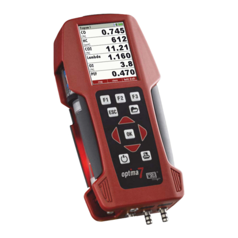
mru OPTIMA7 biogas User manual

4102EN-BIO
OPTIMA7
biogas
USER MANUAL

USER MANUAL OPTIMA7 Biogas
MRU GmbH, D-74172 Neckarsulm 2 / 72
Producer:
Legal notices / Intellectual property rights comments
Original user manual
© 2020 by MRU
No part of this manual my be published in any form (print, fotocopy,
electronic media or any other publication form) without a written approval
by the publisher.
All user trade marks and name mark descriptions, even those which are not
marked as such, are properties of the respective owners.
Edition: 2020-09-29,V1.00.EN

USER MANUAL OPTIMA 7 Biogas
MRU GmbH, D-74172 Neckarsulm 3 / 72
Table of content
1Information for product and safety..................................... 6
1.1. Safety manual .......................................................................................................6
1.2. Safety precautions...............................................................................................6
1.3. Ensure safety .........................................................................................................7
1.4. Important general information EN50379 and VDI4206..........................7
1.5. User guidelines for rechargeable batteries.................................................9
2Introduction......................................................................... 10
2.1. Intended use ...................................................................................................... 10
2.2. About us............................................................................................................... 12
2.3. Packaging............................................................................................................ 13
2.4. Return of hazardous materials ..................................................................... 13
2.5. Return of electronic equipment .................................................................. 13
3Description........................................................................... 14
3.1. Gas flow diagram.............................................................................................. 14
3.2. Analyzer ............................................................................................................... 15
3.3. Condensate separator..................................................................................... 16
3.4. Probes................................................................................................................... 17
4Operating............................................................................. 18
4.1. Display.................................................................................................................. 18
4.2. Keypad.................................................................................................................. 19
4.3. Menu structure.................................................................................................. 20
5First usage............................................................................ 21
5.1. Preparatory steps.............................................................................................. 21
5.2. Analyzer settings............................................................................................... 21
5.3. Setting measurement ..................................................................................... 21
5.4. Switch-ON protection ..................................................................................... 22
5.5. Setting printer type and print out............................................................... 23
5.6. Setting Bluetooth parameters...................................................................... 24
5.7. Setting date and time...................................................................................... 25
5.8. Configuring measurement programs........................................................ 25
Setting CO limit value (only gas flue measurement) .................................... 26
Configuration of the measurement window (display content) – only
Biogas measurement............................................................................................... 26
Configuration of the measurement window (display content) – only Flue
gas measurement ..................................................................................................... 27
Configuring zoom window.................................................................................... 28
6Preparing measurement..................................................... 29
6.1. Ensure power supply....................................................................................... 29
6.2. Automatic Auto-off function ........................................................................ 29
6.3. Measuring with grid power supply / Battery charging........................ 29
6.4. Battery charge condition ............................................................................... 29
6.5. Operating temperature .................................................................................. 30
6.6. Controlling Condensate separator (water trap) ..................................... 30

USER MANUAL OPTIMA7 Biogas
MRU GmbH, D-74172 Neckarsulm 4 / 72
6.7. Connections and tightness ............................................................................31
6.8. Automatic zero-pint setting...........................................................................31
6.9. Repeating the zeroing .....................................................................................32
7Performing measurement ..................................................33
7.1. Selecting the measuring program...............................................................33
7.2. Performing Biogas measurement ................................................................34
7.3. Flue gas measurement (option) ...................................................................34
7.4. Setting CO-limit value (only with flue gas measurement)...................35
7.5. Storing measured values ................................................................................35
7.6. Printing measurement values .......................................................................36
7.7. Terminate measurement ................................................................................37
7.8. Last measurement values...............................................................................37
7.9. Pressure measurement (Option) ..................................................................38
7.10. Differential temperature measurement (option)....................................39
8Data Storage ........................................................................40
8.1. Organizing data storage..................................................................................40
8.2. Calling up information about data storage..............................................41
8.3. Site administration............................................................................................41
Create new site ...........................................................................................................42
View sites......................................................................................................................42
View sites......................................................................................................................43
Searching site..............................................................................................................43
Changing sites ............................................................................................................44
Deleting sites...............................................................................................................44
8.4. Data transfer using SD card............................................................................46
Importing sites............................................................................................................46
Exporting sites ............................................................................................................48
Exporting combustion measurements...............................................................49
Exporting differential pressure measurements........................................49
8.5. Measurement in Data storage.......................................................................50
Viewing measurements...........................................................................................50
Deleting measurements..........................................................................................51
Transferring measurements to SD-Card (Option)...........................................52
9Extras / Adjustments ...........................................................53
9.1. Service calibration menu ................................................................................53
9.2. Default settings..................................................................................................54
9.3. Service values......................................................................................................55
9.4. Leak proof test....................................................................................................56
9.5. Contents SD card...............................................................................................57
9.6. Contents Analyzer information.....................................................................58
10 Maintenance and care.........................................................59
10.1. Maintenance .......................................................................................................59
10.2. Service messages...............................................................................................59

USER MANUAL OPTIMA 7 Biogas
MRU GmbH, D-74172 Neckarsulm 5 / 72
11 Appendix.............................................................................. 60
11.1. Technical data.................................................................................................... 60
General data ............................................................................................................... 60
Measured values ....................................................................................................... 60
11.2. Analysis and calculations ............................................................................... 63
11.3. Text input ............................................................................................................ 67
11.4. Asking user for decision ................................................................................. 67
11.5. Firmware update .............................................................................................. 68
Install the new software version in the analyzer............................................ 68
Performing and checking the update................................................................ 68
In case of error ........................................................................................................... 69
11.6. Troubleshooting ............................................................................................... 70
Troubleshooting the analyzer .............................................................................. 70
Troubleshooting condensate separator ........................................................... 71
12 Declaration of conformity .................................................. 72

USER MANUAL OPTIMA7 Biogas
MRU GmbH, D-74172 Neckarsulm 6 / 72
1Information for product and safety
1.1. Safety manual
All general information and safety precautions of MRU products are listed in
the supplied separate safety manual.
Therefore, this manual must be read and observed before the first use of the
instrument.
Instrument-specific safety and warning requirements in this manual are pre-
fixed before dangerous actions.
1.2. Safety precautions
The used categories of safety precautions are here explained once more
DANGER
Identifies an immediate, impending hazard that, if
ignored, will result in severe bodily injuries or death.
WARNING
Identifies an immediate, impending hazard that, if
ignored, may result in severe bodily injuries, material dam-
age or death.
CAUTION
Identifies a possibly dangerous situation that, if
ignored, may result in minor injuries.
ATTENTION
Identifies a possibly harmful situation that, if ignored, may
result in damages to the device or its
surroundings.
NOTE
Identifies user tips and other especially important infor-
mation.
The explanation of safety notices:
CAUTION
HOT – danger of burns and fire hazards from gas ex-
traction probe.
Physical harm and property damage can be caused.
►Cool down the probe tube.

USER MANUAL OPTIMA 7 Biogas
MRU GmbH, D-74172 Neckarsulm 7 / 72
1.3. Ensure safety
►Please read the user manual completely before the first use.
►Only use the analyzer for the intended use and within the parameters
specified in the technical data.
►Do not use any violence.
►Avoid falls.
►Do not put the analyzer into use, if the housing, power supply unit or sup-
ply leads are damaged.
►Do not store the analyzer together with solvents. Do not use
desiccants.
►Only carry out maintenance and service work on this analyzer as de-
scribed in the User Manual. Observe the prescribed action steps.
►Operate the analyzer only in closed, dry rooms and protect it from rain
and moisture.
►When operating the analyzer on mains power, operate it only with the
mains adapter supplied.
►Do not use the metal tube of the gas sampling probe or other metallic
parts / accessories as electrical conductors.
►The analyzer must not be located in the immediate vicinity of open fire or
great heat.
►The specified temperature range of the gas sampling probe must not be
exceeded, otherwise the probe tube and temperature sensor will be de-
stroyed.
1.4. Important general information EN50379 and VDI4206
This analyzer is not designed to be used for continuous measurements.
Before using the analyzer verify the condition of the various parts of the ana-
lyzer, such as the probe, the ambient air conditions, the condensate separa-
tor, star filter and the connectors for damage and/or blockages.
When starting up the analyzer it will take between 1 – 3 minutes to set to zero
depending on the condition of the sensors and of ambient.
The minimum zeroing time of the analyzer to achieve correct measurement
values can be expected by 1.5 minutes.
Exposure to acids; aggressive gases such as sulphur; vapours such as thin-
ners, gasoline, alcohol and paint, etc. can damage, reduce the life of, or de-
stroy the sensors.
The life of the sensors depends on how they are used, maintained and treated.
Typical average life expectations are: O2- 3 years; CO - 2 - 3 years, H2S 2 years
and NO - 3 years.
The use of the analyzer for regulatory purposes is subject to special regula-
tions (for example a periodical examination of the analyzer). Please obtain the
appropriate regulations from your local responsible authority.

USER MANUAL OPTIMA7 Biogas
MRU GmbH, D-74172 Neckarsulm 8 / 72
Biogas or other similar gases (landfill gas, bio-methane, coal seam gas etc) is
containing flammable component CH4 and toxic component as well (H2S
and CO2).
Analyzers sample a certain volume of the biogas, and vent it to the ambient
air.
For this reason, there are two aspects which must be considered:
1) toxicity danger of sample gas
2) flammable (explosion) danger of sample gas
1) Inhaling toxic gases is harmful to health and can even cause death in
some cases.
•It is the responsibility of analyzer user to ensure that person is skilled and
trained in safety aspects of gases being analyzed and procedures to fol-
low while using this instrument.
•Local regulations for possible exposition to toxic gases have to be known
by the user and obeyed by the user of the analyzer
•Using a personal gas detector inside the biogas plant is highly recom-
mended since H2S in higher (very dangerous concentration) cannot be
detected by human nose. Only small concentrations around few ppm can
be detected by human nose
•CO2 gas is heavier than air and therefore operator shall avoid using porta-
ble biogas analyzer at underground levels. Beside of that CO2 is also
odourless!
•It is not allowed using the portable biogas analyzer in confined space or
rooms without sufficient ventilation.
•Sample gas exiting the analyzer will flow in the ambient air and only out-
door use or forced ventilation rooms are suitable for using the portable
biogas analyzer
2) Regarding flammable gases (e.g. CH4 methane) and hazardous area of op-
erating the instruments, user must also be able to recognize the area classifi-
cation and be aware of using the instrument there. This area classification is
country specific, please observe and notice it.
•MRU instruments may be operated in hazardous areas zone 2 by skilled
users obeying local guidelines e.g. by using LEL gas detectors

USER MANUAL OPTIMA 7 Biogas
MRU GmbH, D-74172 Neckarsulm 9 / 72
1.5. User guidelines for rechargeable batteries
NOTE
The rechargeable batterie is installed inside the analyzer
and is not accessible to the end customer. However, the
following instructions must generally be observed when
handling lithium-ion rechargeable batteries.
•This rechargeable battery can only be used in this analyzer.
•Do not throw the rechargeable battery into a fire, charge it at high tem-
peratures and store it in a hot environment.
•Do not deform, short-circuit or modify the rechargeable battery.
•The rechargeable battery must not be used in or under water.
•Do not expose the rechargeable battery to strong mechanical forces and
do not throw it.
•Do not cut or squeeze the connecting cables of the rechargeable battery.
•Do not connect the (+) contact to the (-) contact or metal.
•Non-observance of the above guidelines can cause heat, fire and explo-
sions

USER MANUAL OPTIMA7 Biogas
MRU GmbH, D-74172 Neckarsulm 10 / 72
2Introduction
•This manual enables you to understand and safely operate this MRU Ana-
lyzer.
•Please read this manual with great vigilant and get familiar with the
product before using it.
•This analyzer may only be operated by competent personnel and for its
intended use.
•Please pay special attention to all safety directions and warnings to pre-
vent personal injuries and damaging of the product.
•We can’t be held responsible for any injuries and/or damages that occur
by not following the instructions in this manual.
•Always keep the manual near you when working with the analyzer, to be
able to read instructions as needed. Please ensure to hand over all docu-
ments to when handing the analyzer over to others.
2.1. Intended use
The OPTIMA 7 BIOGAS analyzer is used for:
•for BIOGAS simultaneous measurements of O2, CH4, CO2, H2S and op-
tional the BIOGAS pressure
•optional for combustion measurements of the engine: O2, CO, NO, NO2
and CO2(NDIR) including the calculation of: mg/m3, NOx as mg/m3 NO2,
true NOx-measurement NOx = NO + NO2, referencing (normalisation) to
user settable value
It can also be used (when options are activated or external equipment is
used) for a number of measurement tasks, such as:
•Flow velocity measurement
•Differential measurement of pressure and temperature
•Combustibles detection with external HC sensor
•Automatic measurement with data logging
You will find a list of all options for this analyzer on our web page or you can
contact MRU or our local representative. The OPTIMA 7 BIOGAS Analyzer is
available in different versions. This manual will describe all versions indicat-
ing options and features not always available on all versions.

USER MANUAL OPTIMA 7 Biogas
MRU GmbH, D-74172 Neckarsulm 11 / 72
The analyzer is specifically not intended as a safety device or personal pro-
tective equipment.
The analyzer should not be used as a warning device to warn people against
the presence of harmful gases.
The analyzer must be used according to instructions for the intended use.
Our analyzers are checked according to the following regulations:
VDE 0411 (EN61010) and DIN VDE 0701 before they leave the MRU GmbH
factory.
MRU technical products are designed and manufactured according to DIN
31000/ VDE 1000 and UVV = VBG 4 of the professional guilds for fine me-
chanics and electrical engineering.
MRU GmbH assures that the analyzer complies to the essential requirements
of the legal regulations of the member states of the electro-magnetic com-
patibility (89/336/EWG)
WARNING
Risk from manipulations to the measuring device
Operational safety hazard
►Modifications or changes to the measuring device are
not allowed.

USER MANUAL OPTIMA7 Biogas
MRU GmbH, D-74172 Neckarsulm 12 / 72
2.2. About us
The analyzer is produced by the MRU GmbH in Neckarsulm, Germany
(Founded in 1984), a medium sized company that specializes in developing,
producing and marketing high quality emission monitoring
analyzers.
MRU GmbH produces a wide range of instruments, from standard
analyzers up to tailor made industrial analyzers.
Plant 1: Sales, Service, R&D
Plant 2 (Production)
Fuchshalde 8 + 12
74172 Neckarsulm - Obereisesheim
GERMANY
Tel +49 71 32 99 62 0 (Front office)
Tel +49 71 32 99 62 61 (Service)
Fax +49 71 32 99 62 20
Email: info@mru.de
Site: www.mru.eu

USER MANUAL OPTIMA 7 Biogas
MRU GmbH, D-74172 Neckarsulm 13 / 72
2.3. Packaging
Save the original carton and packing materials to prevent damage in transit
in case you need to return the unit to the factory.
2.4. Return of hazardous materials
Waste Disposal/Returns/Warranty - MRU GmbH is required to accept the re-
turn of hazardous waste such as electro-chemical sensors that cannot be dis-
posed of locally.
Hazardous waste must be returned to MRU prepaid.
2.5. Return of electronic equipment
MRU GmbH is required to accept the return, for proper disposal, of all analyz-
ers delivered after 13th of August 2005.
Analyzers must be returned to MRU prepaid.

USER MANUAL OPTIMA7 Biogas
MRU GmbH, D-74172 Neckarsulm 14 / 72
3Description
3.1. Gas flow diagram
The analyzer extracts a partial volume of the biogas and analyses it for its
components using NDIR and electrochemical sensors.
Position
Description
1
Biogas sampling hose
2
Connection to gas outlet
3
Condensate separator
4
Star filter
5
Non return valve
6
Gas pump
7
Sensor chamber
8
O2-Sensor
9
Further electrochemical sensors * (CO, NO
2
, H
2
S)
10
CO2/CH4 NDIR Sensor
11
not used
12
Pressure sensor *
*optional

USER MANUAL OPTIMA 7 Biogas
MRU GmbH, D-74172 Neckarsulm 15 / 72
3.2. Analyzer
The compact analyzer is made from a fibre re-enforced plastic material with
all measurement related connections at the bottom of the analyzer.
Position
Description
1
Display
2
Key pad
3
Temperature connector T2
4
Temperature connector T1
5
Pressure connector P1
6
Pressure connector P2
7
Gas outlet
8
IR-Interface
9
USB-port and charging port
10
SD-card reader
11
Fixing magnets
12
Analyzer feet
13
Handle strip
14
Gas outlet
15
Pressure connector P3
16
Connector AUX

USER MANUAL OPTIMA7 Biogas
MRU GmbH, D-74172 Neckarsulm 16 / 72
NOTE
If during zeroing T air (5) is disconnected, then value of T
gas at the end of zeroing will be used. In this case, the
measuring value will be displayed green coloured.
If T air (5) will be connected during the measurement, then
true T air measurement will occur and the display color
changes from green to black
3.3. Condensate separator
•CAUTION
Condensate is acidic
The condensate from the container can be slight acidic and
can cause chemical burn.
►Immediately clean with plenty of water once you have
encountered acid
During the measurement accumulating condensate is collected in the con-
densate separator
ATTENTION
Gas outlet:
During measurement the gas outlet must not be covered

USER MANUAL OPTIMA 7 Biogas
MRU GmbH, D-74172 Neckarsulm 17 / 72
Remove the condensate separator by pulling it towards you (1) out of the
groove of the OPTIMA 7 housing, then pull it downwards (2).
Condensate vessel and plugs are screwed together. To change the filter and
dry and clean the condensate separator this can be easily disassembled and
screwed together again.
After cleaning, a leak test must be carried out.
9.4 Leak proof test, S. 56
In the condensate separator of the OPTIMA7 an exhaust gas filter is at-
tached. This filter out the first coarse dirt. This pocket star filter is washable
and can be used 4-5 times afterwards.
Frequent measurements result in a high degree of contamination which re-
quires regular replacement of this filter.
3.4. Probes
The Analyzer is available with different probes, both with exchangeable
probe tubes.
A complete list of available probes can be found in the current price list of
this analyzer.

USER MANUAL OPTIMA7 Biogas
MRU GmbH, D-74172 Neckarsulm 18 / 72
4Operating
4.1. Display
All information required to operate the analyzer is displayed as shown be-
low.
Position
Description
1
Menu bar
2
Function key bar
3
Display panel
1. Menu
2. Measurement value
4
Zeroing active
5
SD-Card in the slot
1. Indication green
Read- and write access
Indication yellow
only Read access
(SD-Card write protected)
6
Battery charge condition

USER MANUAL OPTIMA 7 Biogas
MRU GmbH, D-74172 Neckarsulm 19 / 72
4.2. Keypad
Description and functions of the keys:
ON/OFF
Press to start the analyzer without de-
lay. The power off function will be de-
layed to protect the sensors. If there is
not enough ambient air the analyzer
will recommend the purging of the
sensors.
Function Keys
Activates the functions seen on the
display (2 function key bar).
Menu Key
Will show all available functions in the
window that is currently in use – also
those which have an individual key on
the key pad like the printer and the
three function keys.
ESC
Abort or return to the menu above
Arrow Keys
Jump in between lines, change
values
OK
Confirmation key, select a marked
menu point
Printer
Activates the printer function in the
measurement and service window

USER MANUAL OPTIMA7 Biogas
MRU GmbH, D-74172 Neckarsulm 20 / 72
4.3. Menu structure
The analyzer organizes all available actions in three main menus:
•Menu Measurement
All available measurement options will be displayed and can be selected
here.
•Menu Storage
All available storage options will be displayed and can be selected here.
•Menu Extra
All other actions are available here to manage and customize the de-
vice.
You can jump in between the 3 main menus with the 3 function keys (ac-
cording to the displayed name on the screen).
OPTIMA 7 Biogas
The topic „Biogas
measurement „is a
standard feature in
every analyzer and
is explained in
chapter 7Perform-
ing measurement,
Page 33. Other
menu points are
optional and will
be explained either
in this manual or in
an additional man-
ual or flyer.
The menu Storage
is explained in
chapter 8Data
Storage, Page 40.
The menu Extra is
explained in Chap-
ter 9Extras / Ad-
justments, Page
53.
Other manuals for OPTIMA7 biogas
1
Table of contents
Other mru Measuring Instrument manuals

mru
mru DM9600 User manual

mru
mru SWG100 BIOGAS User manual

mru
mru SWG100 BIOEX User manual

mru
mru Air Fair MGAprime User manual

mru
mru NOVAplus User manual

mru
mru AMPRO 2000 GOLD User manual

mru
mru OPTIMA 7 BIOGAS User manual

mru
mru Vario Luxx User manual

mru
mru DELTAsmart User manual

mru
mru AMPRO 2000 User manual
Popular Measuring Instrument manuals by other brands

PCB Piezotronics
PCB Piezotronics IMI SENSORS ICP 604B31 Installation and operating manual

Shimpo
Shimpo DT-205L instruction manual

SATO KEIRYOKI
SATO KEIRYOKI SK-650PH instruction manual

Simrad
Simrad PI50 - REV A datasheet

PURGE SOLUTIONS
PURGE SOLUTIONS CYCLOPS Z manual

Midcontinent
Midcontinent MD23-225 user guide