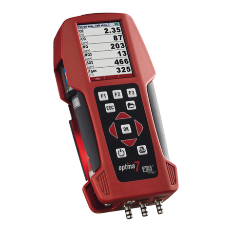
mru MGAprime User manual

MGAprime
USR MANUAL
9452EN-PR

USER MANUAL MGAprime
2 / 104 MRU GmbH, D-74172 Neckarsulm
Producer:
Legal notices / Intellectual property rights comments
Original user manual
© 2021 by MRU
No part of this manual my be published in any form (print, photocopy, electronic
media or any other publication form) without a written approval by the publisher.
All user trade marks and name mark descriptions, even those which are not marked
as such, are properties of the respective owners.
Edition: 2020-02-04, V10.00.EN

USER MANUAL MGAprime
MRU GmbH, D-74172 Neckarsulm 3 / 104
Table of Contents
1Information for product and safety............................................... 7
1.1. Safety manual .................................................................................................7
1.2. Safety precautions.........................................................................................7
2Introduction...................................................................................... 8
2.1. Intended use ...................................................................................................8
2.2. About us ...........................................................................................................9
3Description...................................................................................... 11
3.1. Task.................................................................................................................. 11
3.2. Gas flow diagram........................................................................................ 11
3.3. The Analyser................................................................................................. 13
3.4. Connectors.................................................................................................... 14
3.5. Probes............................................................................................................. 15
3.6. Heated Gas sampling probe................................................................... 16
3.7. Unheated Gas sampling probe.............................................................. 18
3.8. Gas conditioning......................................................................................... 18
3.9. Gas supply..................................................................................................... 19
3.10. Gas sensors................................................................................................... 19
3.11. Acid injection ............................................................................................... 20
4Operation ........................................................................................ 21
4.1. Commissioning............................................................................................ 21
4.2. Operating panel.......................................................................................... 21
4.3. Charging the battery................................................................................. 22
4.4. Switching on the analyser ....................................................................... 23
4.5. Switching off the analyser....................................................................... 23
4.6. Turn Display.................................................................................................. 23
4.7. Set the analyser to standby mode ....................................................... 24
4.8. Back to homescreen / Back to measure............................................. 25
4.9. Create screenshots..................................................................................... 25
5Settings............................................................................................ 26
5.1. Analyser settings......................................................................................... 26
5.2. Setting time and date ............................................................................... 28
5.3. Configuration of measurement program .......................................... 28
Test program ....................................................................................................... 28
Measurement program.................................................................................... 29
Further measuring programs......................................................................... 29
Moving a value field.......................................................................................... 29
Assign a measured value................................................................................. 29
Setting zoom........................................................................................................ 30
5.4. Gas flow measurement............................................................................. 30
Parameter for gas flow measurement ........................................................ 30

USER MANUAL MGAprime
4 / 104 MRU GmbH, D-74172 Neckarsulm
5.5. Operating the analyser in the extended temperature range......32
Precautions for use in the extended temperature range.....................32
Connecting heating box ..................................................................................32
5.6. Operating analyser with NiHM-Battery..............................................34
6Measurement ..................................................................................35
6.1. Prepare measurement............................................................................... 35
Setting up the measuring point....................................................................35
Operating temperature ....................................................................................36
Power supply........................................................................................................36
Opening the transport bag.............................................................................37
Switch-on, warm-up phase, zero point ......................................................37
Repeated Zero point .........................................................................................38
Automatic zero point ........................................................................................38
Use last valid zero point...................................................................................39
Select Source zero point (gas).......................................................................40
Activate NDIR-Fastmode function ...............................................................41
Charging state of the battery.........................................................................42
Connections to the analyser...........................................................................42
Attach clip-on filter............................................................................................44
Controlling Filters...............................................................................................44
Connecting Gas moisture bottle...................................................................45
Connecting Acid Dosing Unit APE................................................................46
Perform leak test.................................................................................................48
6.2. Take a measurement .................................................................................50
Setting O2 reference and Fuel type.............................................................50
Setting CO purge limit......................................................................................50
Starting the measurement ..............................................................................51
Storing measured values .................................................................................51
Selecting channels for Auto-measurement ..............................................52
Starting Auto-measurement...........................................................................55
Stopping Auto-measurement........................................................................57
7Data memory ..................................................................................58
7.1. Organizing data memory.........................................................................58
7.2. Managing sites ............................................................................................58
Adding a new site...............................................................................................58
Changing site data.............................................................................................59
Deleting sites .......................................................................................................60
Recalling stored measurements....................................................................60
7.3. Data transfer via USB (CSV export) ......................................................61
8Extras ...............................................................................................64

USER MANUAL MGAprime
MRU GmbH, D-74172 Neckarsulm 5 / 104
8.1. History ............................................................................................................ 64
8.2. System extensions...................................................................................... 65
8.3. Connections.................................................................................................. 66
8.4. Setting Date / Time.................................................................................... 66
8.5. Programs ....................................................................................................... 66
8.6. Instrument leak test................................................................................... 67
8.7. Default settings ........................................................................................... 68
8.8. Internal log Settings .................................................................................. 68
Copying all log data .......................................................................................... 68
Copying single log data................................................................................... 69
8.9. Analog output setup (4 –20 mA)......................................................... 71
Setting channel ................................................................................................... 71
Setting lower / higher limit............................................................................. 72
Setting Analog outputs during zeroing ..................................................... 73
Pin assignment of the 4-20 mA interface (Analog IN/OUT)............... 74
8.10. Analog input setup (4-20mA) ................................................................ 74
8.11. Connecting analyser with WIFI (WLAN) ............................................. 75
8.12. Getting information about the network............................................. 77
8.13. Assigning a fixed IP address................................................................... 78
8.14. Serial connectivity (RS485/USB)............................................................ 79
8.15. Printing measurement results................................................................ 79
Printing current measurement results........................................................ 80
Printing stored measurement results.......................................................... 80
8.16. Service values............................................................................................... 82
8.17. Access key..................................................................................................... 82
9Info................................................................................................... 83
10 Maintenance and cleaning......................................................... 84
10.1. Cleaning and maintenance ..................................................................... 84
10.2. Service check................................................................................................ 84
11 Simple service work.................................................................... 85
11.1. Information of the analyser components.......................................... 85
11.2. Updating the firmware ............................................................................. 85
12 Specifications .............................................................................. 87
12.1. Specifications of NDIR technology ...................................................... 87
12.2. Sensors for Oxygen, Temperatures and Pressure........................... 88
12.3. Gas sampling and conditioning ............................................................ 88
12.4. Calculated values and accessories ....................................................... 89
12.5. Data communication................................................................................. 89
12.6. Technical data.............................................................................................. 89
12.7. Technical data Acid Dosing Unit APE.................................................. 90

USER MANUAL MGAprime
6 / 104 MRU GmbH, D-74172 Neckarsulm
13 Appendix...................................................................................... 91
13.1. Error diagnosis regarding the measuring instrument...................91
13.2. Switching off the analyser in case error .............................................92
13.3. RS485 Extern (Option)...............................................................................93
13.4. Screw adapter onto HPI-Probe (Option)............................................94
13.5. Connecting analyser with MRU4win....................................................94
Connecting analyser with MRU4win via serial interface (RS 485).....94
Connecting analyser with MRU4win via TCP/IP connection............... 95
Creating analyser in MRU4win ......................................................................96
13.6. Remote control of the analyser device via VNC..............................99
13.7. General Instructions for the heated hose line................................100
Unrolling the heated hose line ....................................................................100
Bending radius of heated sampling lines ................................................101
13.8. CxHy Calculation.......................................................................................102
13.9. Spare parts..................................................................................................102
14 Declaration of conformity........................................................103

USER MANUAL MGAprime
MRU GmbH, D-74172 Neckarsulm 7 / 104
1Information for product and safety
1.1. Safety manual
All general information and safety precautions of MRU products are
listed in the supplied separate safety manual.
Therefore, this manual must be read and observed before the first use
of the instrument.
Instrument-specific safety and warning requirements in this manual are
prefixed before dangerous actions.
1.2. Safety precautions
The used categories of safety precautions are here explained once
more.
DANGER
Identifies an immediate, impending hazard that, if
ignored, will result in severe bodily injuries or death.
WARNING
Identifies an immediate, impending hazard that, if
ignored, may result in severe bodily injuries, material
damage or death.
CAUTION
Identifies a possibly dangerous situation that, if
ignored, may result in minor injuries.
ATTENTION
Identifies a possibly harmful situation that, if ignored,
may result in damages to the device or its
surroundings.
NOTE
Identifies user tips and other especially important infor-
mation.
The explanation of safety notices:
CAUTION
HOT –danger of burns and fire hazards from gas
extraction probe.
Physical harm and property damage can be caused.
►Cool down the probe tube.

USER MANUAL MGAprime
8 / 104 MRU GmbH, D-74172 Neckarsulm
2Introduction
•This manual enables you to understand and safely operate this
MRU Analyzer MGAprime.
•Please read this manual with great vigilant and get
familiar with the product before using it.
•This analyser may only be operated by competent personnel
and for its intended use.
•Please pay special attention to all safety directions and warn-
ings to prevent personal injuries and damaging of the product.
•We can’t be held responsible for any injuries and/or damages
that occur by not following the instructions in this manual.
•Always keep the manual near you when working with the ana-
lyser, to be able to read instructions as needed. Please ensure
to hand over all documents to when handing the analyser over
to others.
2.1. Intended use
The Analyzer MGAprime is designed for the gas analysis of flue gases,
as they are emitted from gas/oil burners, engines, or heating and power
appliances.
The analyser is intended to support the user in control and indicative
measurements in an efficient, accurate and reliable way.
The analyser is specifically not intended as a safety device or personal
protective equipment.
The analyser should not be used as a warning device to warn people
against the presence of harmful gases.
The analyser was manufactured according relevant standards and
regulations.
The analyser must be used according to instructions for the intended
use.
WARNING
Risk from manipulations to the measuring device
Operational safety hazard
►Modifications or changes to the measuring device are
not allowed.

USER MANUAL MGAprime
MRU GmbH, D-74172 Neckarsulm 9 / 104
Syntax
Please note that this manual makes use of the scientific notation of
gases (NO2), while the instrument itself and its screen shots display the
gases in upper case letter only, i.e. (NO2).
2.2. About us
The analyser is produced by the MRU GmbH in Neckarsulm, Germany
(Founded in 1984), a medium sized company that is specialised in
developing, producing and marketing high quality emission monitoring
analysers.
MRU GmbH produces a wide range of instruments, from standard
analysers up to tailor made industrial analysers.
Building 1: Sales, Service, R&D
Building 2: Production

USER MANUAL MGAprime
10 / 104 MRU GmbH, D-74172 Neckarsulm
MRU GmbH
Fuchshalde 8 + 12
74172 Neckarsulm - Obereisesheim
GERMANY
Tel +49 71 32 99 62 0 (Front office)
Tel +49 71 32 99 62 61 (Service)
Fax +49 71 32 99 62 20
Email: [email protected]
Site: www.mru.eu

USER MANUAL MGAprime
MRU GmbH, D-74172 Neckarsulm 11 / 104
3Description
3.1. Task
The main task of the analyser is to analyse
flue gases, as they are emitting from incinerators or engines.
•The analyser is optimized for this purpose and includes all
components from the gas sampling probe to data processing.
•The analyser also performs other measurement tasks such as
pressure and temperature measurement or measurement of
flow velocity.
For an overview on all available options please refer to the company’s
home page or sales representatives.
3.2. Gas flow diagram
In combination with the gas sampling probe, the analyser extracts a par-
tial volume of the flue gas from the combustion channel and
analyses it for its components by means of sensors (e.g., paramagnetic
(oxygen) sensor, electrochemical (oxygen) sensor or NDIR sensors).
Draft and temperature are measured at the tip of the sampling probe.
With paramagnetic oxygen sensor

USER MANUAL MGAprime
12 / 104 MRU GmbH, D-74172 Neckarsulm
A
Fresh air inlet
B
Sample gas inlet
C
Condensate outlet
D
Diff. Pressure connector
E
Vent collection box
F
Vent outlet
1
Sample gas filter (PTFE)
2
Dust filter
3
Auto-zero solenoid valve
4
Sample gas pump
5
Double stage gas cooler
6
Sample flow sensor
7
Paramagnetic sensor
8
Not used
9
Infrared (NDIR) bank
10
Acrodisc PTFE filter
11
Diff. pressure sensor
With electrochemical oxygen sensor
A
Fresh air inlet
B
Sample gas inlet
C
Condensate outlet
D
Diff. Pressure connector
F
Vent collection box
E
Vent outlet
1
Sample gas filter (PTFE)
2
Dust filter
3
Auto-zero solenoid valve
4
Sample gas pump
5
Double stage gas cooler
6
Sample flow sensor
7
Electrochemical O2 sensor
8
Sample gas outlet pump
9
Infrared (NDIR) bank
10
Acrodisc PTFE filter
11
Diff. pressure sensor

USER MANUAL MGAprime
MRU GmbH, D-74172 Neckarsulm 13 / 104
3.3. The Analyser
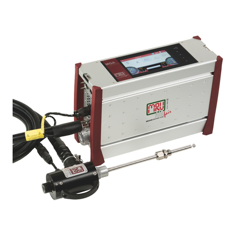
The analyser consists of a compact and robust metal
housing with shock-absorbing rubber corners. All electrical and pneu-
matic connections are located on the both front sides of the instrument.
It is operated exclusively via the touch-sensitive touch screen.

USER MANUAL MGAprime
14 / 104 MRU GmbH, D-74172 Neckarsulm
3.4. Connectors
Front side right
1
Loudspeaker
2
Ethernet (LAN)
3
USB socket
4
Second USB socket (option)
5
RS485 (Option)
6
Analog outputs 4 ... 20 mA
Analog-inputs 4 … 20 mA
7
Mains power supply
Front side left
8
Sample gas filter
9
Condensate outlet port
Hose connection DN 4/6
10
Sample gas outlet port
(VENT) Hose connection DN
4/6
11
Fresh air inlet port
12
Sample gas inlet port
13
Outlet fan of gas cooler
14
Probe connection, electrical
15
Pressure-/diff. pressure
16
Pressure-/diff. pressure
(Absolute pressure)
17
Combustion air temperature
18
AUX socket
19
Connection acid injection
(Option)
20
Connection acid injection
(Option)

USER MANUAL MGAprime
MRU GmbH, D-74172 Neckarsulm 15 / 104
The connection drawings are also displayed in the menu Extras.
►Touch the menu Extras.
A selection list appears.
►Press „Connections“.
The left side of the analyser appears.
►Push „Right >>“.
The right side of the analyser appears.
3.5. Probes
In combination with the analyser, probes in different versions are of-
fered.
•for fuel temperatures up to 800 °C (stainless-steel probe tube),
•for fuel temperatures up to 1.100 °C (Inconel steel probe tube),
•probe tubes in different lengths
A complete list of available probes can be found in the current price list
of this analyser.

USER MANUAL MGAprime
16 / 104 MRU GmbH, D-74172 Neckarsulm
3.6. Heated Gas sampling probe
For interchangeable probe tube with flue gas temperature measure-
ment using type K-thermoelement.
1
Probe handle
2
Probe tube
3
Fast locking coupling
4
Probe cone
5
Cable plug (14-pin)
6
Heated hose line
7
Cable coupler (5-pin)
8
Fast locking coupling
9
Filter lock
►Check the probe filter before and after every measurement.
WARNING
Danger of burns and fire hazards from Heated hose
line
Injuries and burns may result.
►Roll out the heated hose line completely for each
measurement.

USER MANUAL MGAprime
MRU GmbH, D-74172 Neckarsulm 17 / 104
NOTE
Please note that heating hoses with 110V and 230V are
offered.
►Check the voltage supply of the heating hose before
commissioning.
►You can operate a 230V heating hose with 110 volts,
but with limited heat capacity.
DANGER
Risk due to improper use
Risk of death due to electric shock
►Do not operate a 110V heating hose with 230V.
See also chapter 13.7 General Instructions for the heated hose
line, Page 100.
ATTENTION
When measuring with coiled heated hose line, the hose
line is destroyed due to strong heat development.
►Roll out the heated hose line completely for each
measurement.

USER MANUAL MGAprime
18 / 104 MRU GmbH, D-74172 Neckarsulm
3.7. Unheated Gas sampling probe
1
Filter lock
2
Fast locking coupling
3
Cable coupler (5-pin)
4
Cable plug (14-pin)
5
Fast locking coupling
6
Unheated hose line
7
Probe cone
8
Probe tube
9
Probe handle
►Check the probe filter before and after every measurement.
3.8. Gas conditioning
The sucked sample gas is dried and filtered before it is fed to the
sensors.
A sample gas cooler with Peltier element is used for drying.
The condensate liquid appearing in the gas cooler is pumped to the
condensate outlet by means of a peristaltic pump. The condensate
forms drops at the outlet of the instrument.

USER MANUAL MGAprime
MRU GmbH, D-74172 Neckarsulm 19 / 104
Optionally, connect a hose (DN 4/6) to the condensate drain.
A hose (DN 4/6, not longer than 5 m) can also be connected to the
sample gas outlet for discharge.
For subsequent filtering, a round filter is used on the front of the
Analyze.
3.9. Gas supply
The analyser contains a gas feed pump (diaphragm pump).
The flow through the gas feed pump is measured and regulated to the
nominal value by the analyser.
If the pump capacity is not sufficient to reach the flow of the nominal
value, an alarm is issued.
If the flow does not reach the nominal value despite an increase of the
pump capacity, the pump is switched off after a while to protect the an-
alyser.
3.10.Gas sensors
The analyser has three types of gas sensors:
1. The aanalyser works with an electrochemical sensor for the
measurement of O2 (oxygen). If an electrochemical sensor for
measuring O2(oxygen) is installed, optionally H2(hydrogen) and
H2S (hydrogen sulphone) can be measured with electrochemical
sensors.
2. The analyser works with paramagnetic sensor for the
Measurement O2 (oxygen).
3. The analyser works with a non-dispersive infrared absorption
measurement.
Depending on the installed NDIR module, it is possible to meas-
ure up to 8 gases with this measuring principle: CO (carbon mon-
oxide), CO2(carbon dioxide), NO (nitrogen monoxide), NO2(ni-
trogen dioxide), N2O (nitrous oxide), SO2(sulphur dioxide), CH4
(methane) and C3H8(propane).

USER MANUAL MGAprime
20 / 104 MRU GmbH, D-74172 Neckarsulm
3.11.Acid injection
CAUTION
Phosphoric acid (10 %)
Phosphoric acid (10 %) may cause burns.
►If you come into contact with acid, wash the area im-
mediately using a lot of water.
►Note the safety data sheet for phosphoric acid
(10%).
Phosphoric acid (10 %) is injected into the analyser using the
Acid Dosing Unit APE
The injection of phosphoric acid (10 %) is necessary for a correct
measurement.
•The injection guarantees constant conditions in the gas cooler, so
that you can measure dry or humid flue gas.
•The use of phosphoric acid (10%) reduces losses of SO2, NO2on
the humid surfaces of the gas cooler.
Both effects increase measurement accuracy by preventing slow drift ef-
fects caused by slowly forming or saturating moisture films.
Two pumps inject 24ml of phosphoric acid (10%) per hour during the
measurement.
A collecting bottle is included in the scope of delivery.
►Please note that the volume of the supplied collecting bottle is suffi-
cient for two hours of measuring operation.
See also chapter Connecting Acid Dosing Unit APE, Page 46 to
connect the Acid Dosing Unit APE to the analyser.
Other manuals for MGAprime
3
Table of contents
Other mru Measuring Instrument manuals

mru
mru SYNGAS VARIOluxx User manual

mru
mru DM 9600 CHP User manual

mru
mru AMPRO 2000 User manual

mru
mru Air Fair MGAprime User manual

mru
mru AMPROplus User manual

mru
mru NOVAplus biogas User manual

mru
mru AIR fair SWG 100 biogas User manual

mru
mru VARIOluxx User manual

mru
mru OPTIMA7 biogas User manual

mru
mru OPTIMA User manual
Popular Measuring Instrument manuals by other brands

Decagon
Decagon AQUA LAB VSA quick start guide

WATANABE ELECTRIC INDUSTRY
WATANABE ELECTRIC INDUSTRY A2200 Series Operation manual

Commercial Electric
Commercial Electric MS8301A Use and care guide

nologo
nologo ADR3000 user manual

Agilent Technologies
Agilent Technologies 4155C user guide

Primes
Primes PowerLossMonitor PLM Series operating manual