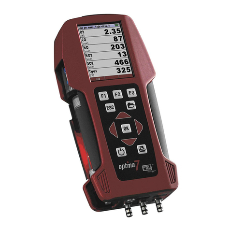
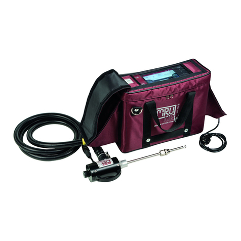
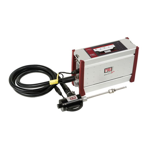
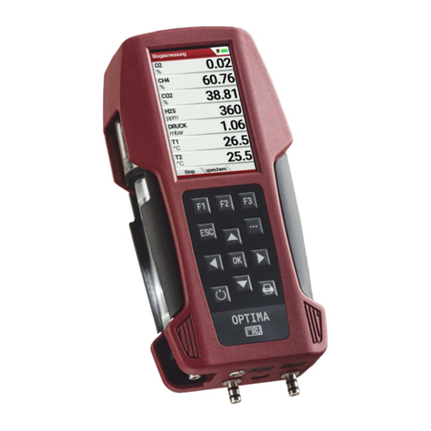
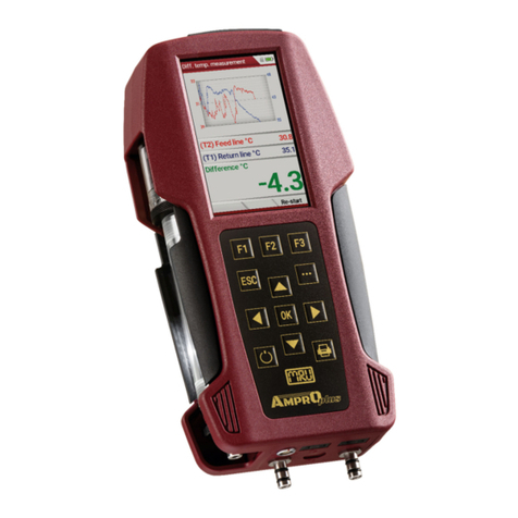
mru Optima 7 User manual

Operation manual OPTIMA7
MRU GmbH, D-74172 Neckarsulm 1 / 51
6902EN

Operation manual OPTIMA7
2 / 51 MRU GmbH, D-74172 Neckarsulm
Manufacturer:
Legal notices / Intellectual property rights comments
Original user manual
© 2018 by MRU
No part of this manual my be published in any form (print, fotocopy, electronic media or
any other publication form) without a written approval by the publisher.
All user trade marks and name mark descriptions, even those which are not marked as
such, are properties of the respective owners.
Edition: 20190227-V2.0

Operation manual OPTIMA7
MRU GmbH, D-74172 Neckarsulm 3 / 51
Content
1Introduction ................................................................................................................. 5
1.1. Intended use .........................................................................................................5
1.2. The company MRU GmbH ................................................................................6
1.3. Analyzer details ....................................................................................................7
1.4. Packaging...............................................................................................................7
1.5. Return of hazardous materiales......................................................................7
1.6. Return of electronic equipment .....................................................................7
2Safety............................................................................................................................ 8
2.1. Safety details .........................................................................................................8
2.2. Ensure safety .........................................................................................................9
Lithium-Ion battery user guidelines
.......................................................9
3Description................................................................................................................. 10
3.1. The Analyzer....................................................................................................... 11
3.2. The condensate separator (water trap)..................................................... 12
3.3. Extraction probes.............................................................................................. 13
3.4. The display.......................................................................................................... 14
3.5. The keypad.......................................................................................................... 14
3.6. Menu configuration......................................................................................... 15
4First usage .................................................................................................................. 16
4.1. Preparing steps.................................................................................................. 16
4.2. Settings ................................................................................................................ 16
4.3. Switch-ON protection ..................................................................................... 17
4.4. Setting printer type and print out............................................................... 18
4.5. Bluetooth settings............................................................................................ 18
4.6. Set time and date.............................................................................................. 19
4.7. Measurement program configuration....................................................... 19
4.8. Set CO limits ....................................................................................................... 19
4.9. Select fuel types and O2reference.............................................................. 20
4.10. User definable fuel types (only If combustion calculation is ON)..... 21
4.11. Define the measuring window..................................................................... 22
4.12. Define of the zoom function......................................................................... 22
4.13. Change measurement program names.................................................... 22
4.14. Core flow search................................................................................................ 22
5Maintenance .............................................................................................................. 23
5.1. Cleaning............................................................................................................... 23
5.2. Annual service and calibration..................................................................... 23
6Preparation for each measurement ......................................................................... 24
6.1. Power supply...................................................................................................... 24
6.2. Auto OFF.............................................................................................................. 24
6.3. Measurement with battery charger/battery charging......................... 24
6.4. Measurement with battery (Battery monitoring) .................................. 24
6.5. Operation temperature .................................................................................. 24

Operation manual OPTIMA7
4 / 51 MRU GmbH, D-74172 Neckarsulm
7Operation ................................................................................................................... 25
7.1. Power ON and zeroing.................................................................................... 25
7.2. Selection of the measurement program................................................... 25
7.3. Combustion test................................................................................................ 26
7.4. Core flow search................................................................................................ 26
7.5. Measured value display .................................................................................. 27
7.6. Non-continuous draft measurement......................................................... 27
7.7. CO-limit (without purging)............................................................................ 28
7.8. CO-purging (optional)..................................................................................... 28
7.9. CO/H2 and CO high (optional) ..................................................................... 28
7.10. Test program...................................................................................................... 29
7.11. CO-ambient ........................................................................................................ 29
7.12. Temporary buffer.............................................................................................. 30
7.13. Storage the measuring results ..................................................................... 30
7.14. Printing the measuring results..................................................................... 31
7.15. Last measurement results.............................................................................. 31
7.16. Pressure measurement................................................................................... 32
7.17. Differential temperature measurement (optional) ............................... 32
7.18. Last measured values ...................................................................................... 32
8Data Storage .............................................................................................................. 33
8.1. Data storage organisation ............................................................................. 33
8.2. Data storage information............................................................................... 33
8.3. Sites administration ......................................................................................... 33
8.4. New entry and change of sites..................................................................... 35
8.5. Delete sites.......................................................................................................... 35
8.6. Data transfer using the SD card ................................................................... 36
8.7. Measurement in Data storage...................................................................... 38
9Extras / Adjustment ................................................................................................... 40
9.1. Service calibration menu ............................................................................... 40
9.2. Factory settings................................................................................................. 40
9.3. Service values..................................................................................................... 40
9.4. Analyzer and accessories leak test.............................................................. 41
9.5. Contents SD card .............................................................................................. 42
9.6. Contents Analyzer information,................................................................... 43
10 Appendix ................................................................................................................ 44
10.1. Text input ............................................................................................................ 44
10.2. Asking user for a decision .............................................................................. 44
10.3. Firmware update............................................................................................... 45
10.4. Using the USB Port ........................................................................................... 45
10.5. Technical data.................................................................................................... 46
Analisis and calculations............................................................................................. 48
10.6. Fuel type list ....................................................................................................... 48
10.7. Troubleshooting ............................................................................................... 49
10.8. Declaration of conformity OPTIMA7........................................................ 51

Operation manual OPTIMA7
MRU GmbH, D-74172 Neckarsulm 5 / 51
1Introduction
•This manual enables you to understand and safely operate this OPTIMA7
combustion analyzer.
Please read this manual with great vigilant and get familiar with the product
before using it.
•This analyzer may only be operated by competent personnel and for its in-
tended use.
•Please pay special attention to all safety directions and warnings to prevent
personal injuries and damaging of the product.
•We can’t be held responsible for any injuries and/or damages that occur by
not following the instructions in this manual.
•Always keep the manual near you when working with the analyzer, to be
able to read instructions as needed.
Please ensure to hand over all documents to when handing the analyzer
over to others.
1.1. Intended use
The OPTIMA7 analyzer is intended for short-term measurement in the context of emission
control measurements and adjustments at small furnaces. The analyzer measures the
measurements provided by VDI4206 and EN50379 metrics and stores them for further pro-
cessing.
The OPTIMA7 analyzer is specifically not intended as a safety device or personal protective
equipment; it should not be used as a warning device to warn people against the presence
of harmful gases.
The OPTIMA7 analyzer may only be used as indicated in this manual. Our analyzers are
checked according to the following regulations: VDE 0411 (EN61010) and DIN VDE 0701
before they leave the MRU GmbH factory.
MRU technical products are designed and manufactured according to DIN 31000/ VDE
1000 and UVV = VBG 4 of the professional guilds for fine mechanics and electrical engi-
neering.
MRU GmbH assures that the analyzer complies to the essential requirements of the legal
regulations of the member states of the electro-magnetic compatibility (89/336/EWG).

Operation manual OPTIMA7
6 / 51 MRU GmbH, D-74172 Neckarsulm
1.2. The company MRU GmbH
The OPTIMA7 analyzer is manufactured by the MRU GmbH in Neckarsulm Germany
(founded in 1984), a medium sized company that specializes in developing, producing and
marketing high quality emission monitoring analyzers. MRU GmbH produces a wide range
of instruments, from standard analyzers up to tailor made industrial analyzers. MRU GmbH
contact details are listed on the previous page.
Plant 1: Sales, Service, R&D
Plant 2: Production
MRU GmbH
Fuchshalde 8 + 12
74172 Neckarsulm - Obereisesheim
GERMANY
Phone +49 71 32 99 62 0 (Front office)
Phone +49 71 32 99 62 61 (Service)
Fax +49 71 32 99 62 20
Email: info@mru.de
Internet: www.mru.eu

Operation manual OPTIMA7
MRU GmbH, D-74172 Neckarsulm 7 / 51
1.3. Analyzer details
•The analyzer is not suitable for long term (continuous) measurements (this is
a spot analyzer).
•Before using the analyzer verify the condition of the various parts of the ana-
lyzer, such as the probe, the ambient air conditions, the condensate separa-
tor, star filter and the connectors for damage and/or blockages.
•When starting the analyzer up it will take between 1 – 3 minutes to set to
zero depending on the condition of the sensors and ambient conditions.
(Zeroing).
•The minimum zeroing time of the analyzer to achieve correct measurement
values can be expected by 1.5 minutes!
•Caution: Exposure to acids; aggressive gases such as Sulphur; vapors such
as thinners, gasoline, alcohol and paint, etc. can damage, reduce the life of,
or destroy the sensors.
•The life of the sensors depends on how they are used, maintained and
treated. Typical average life expectations are: O2 - 2 years; CO - 2 - 3 years
and NO - 3 years.
•The battery life is at least 500 charge-discharge cycles. With increasing num-
ber of charging cycles the battery capacity (indicated in operating hours) is
reduced.
1.4. Packaging
Please keep and store the packaging material to be able to use it when your analyzer must
be sent back for service and calibration.
1.5. Return of hazardous materiales
Waste Disposal/Returns/Warranty - MRU GmbH is required to accept the return of hazard-
ous waste such as electro-chemical sensors that cannot be disposed of locally.
Hazardous waste must be returned to MRU prepaid.
1.6. Return of electronic equipment
MRU GmbH is required to accept the return, for proper disposal, of all analyzers delivered
after 13th of August 2005.
Analyzers must be returned to MRU prepaid.

Operation manual OPTIMA7
8 / 51 MRU GmbH, D-74172 Neckarsulm
2Safety
Safety and warning notices point out possible dangers to the reader of this manual.
In this manual safety and warning notices are typically above actions that might cause
harm or danger.
2.1. Safety details
The explanation of safety notices:
Not following the safety and warning notices may cause physical harm and/or property
damages, as well as the loss of warranty of your analyzer.
The following safety and warning notices must be obeyed at any time!
•DANGER
Describes an immediate threat of danger which can cause mayhem or
can even cause death.
•WARNING
Describes an immediate threat of danger which can cause mayhem,
property damage or can even cause death.
•CAUTION
Describes a possible danger that can cause risk of injury.
ATTENTION
Describes a possible harmful situation which can damage the analyzer or
its surroundings.
NOTE
Gives user hints and other important information.
The explanation of safety notices:
•CAUTION
HOT – danger of burns and fire hazards from gas extraction probe.
Physical harm and property damage can be caused.
►Cool down the probe tube.

Operation manual OPTIMA7
MRU GmbH, D-74172 Neckarsulm 9 / 51
2.2. Ensure safety
•The analyzer may only be used for its intended purpose and within its de-
fined technical parameters. Don’t use any force and avoid dropping the ana-
lyzer.
•Don’t use the analyzer when there are visible damages of the enclosure, the
charger or supply lines.
•Don’t store the analyzer together with solvents and don’t use any drying
agents.
•Only perform maintenance procedures that are described in this manual and
always obey the instructions.
•Only operate the analyzer in closed and dry rooms, protect the analyzer
against rain and moisture.
•Only operate the analyzer with the supplied battery charger.
•Never us the probe tube and other metal parts / accessories as electric con-
ductors.
•The analyzer may not be positioned near open fire or extreme heat.
•The defined temperature range of the extraction probe / probe tube may
not be exceeded, the probe tube and/or thermo-element can be destroyed.
Lithium-Ion battery user guidelines
NOTE
The battery is inside the analyzer and is not accessible to the
end-user.
Below are some guidelines you need to know about Lith-
ium Ion batteries and the handling of these
.
•The rechargeable battery may only be used for this OPTIMA7analyzer.
•Don’t charge the analyzer in extreme heat, don’t store the battery in a hot
environment and don’t throw the battery into fire.
•Don’t try to modify the battery, shortcut it or put any mechanical force to it!
•The battery may not be used in or under water.
•Avoid mechanical force and don’t throw that battery.
•Don’t cut or squeeze the battery cables!
•Don’t carry or store the battery together with sharp objects.
•Don’t connect the (+) contact with the (-) contact or connect these to a
metal object.
•Not obeying the above instructions can cause heat, fire and explosion.

Operation manual OPTIMA7
10 / 51 MRU GmbH, D-74172 Neckarsulm
3Description
The main task of the OPTIMA7 analyzer is to assist with precision control and adjustment
measurements of gas, oil and wood fired furnaces.
Available options for this and other analyzers can be found on the MRU Homepage or
speak to a member of our sales team.
Gas schematics diagram
In combination with the extraction probe (inserted in the stack) the internal gas pump of
the OPTIMA7 analyzer extracts a portion of the flue gas and analyzes it using electro-chemi-
cal sensors.
The thermo-element in the probe tube measures the flue gas temperature and due to the
construction of the probe pressure (draft) can be measured as well.
1
Sampling probe
2
Triple hose
3
Condensate separator
4
Star filter
5
Non return valve
6
Gas pump
7
Sensor chamber
8
O2-Sensor
9
Further electrochemical sensors optional*
10
CO2 NDIR *
11
CO Purge pump * / not available with CO2-NDIR
12
Pressure sensor *
*optional

Operation manual OPTIMA7
MRU GmbH, D-74172 Neckarsulm 11 / 51
3.1. The Analyzer
The compact analyzer is made from a fiber re-enforced plastic material with all measure-
ment related connections at the bottom of the analyzer.
1
Display
2
Key pad
3
Temperature connector T2
4
Temperature connector T1
5
Pressure connector P1
6
Pressure connector P2
7
Gas outlet
8
IR-Interface
9
USB-port and charging port
10
SD-card reader
11
Fixing magnets
12
Analyzer feet
13
Handle strip
14
Gas outlet
15
Pressure connector P3
16
Connector AUX
,
IMORTANT
Gas outlet:
During measurement the gas outlet must not be covered

Operation manual OPTIMA7
12 / 51 MRU GmbH, D-74172 Neckarsulm
3.2. The condensate separator (water trap)
During the measurement accumulating condensate is collected in the condensate separa-
tor
Remove the condensate separator by pulling it towards you (1) out of the groove of the
OPTIMA 7 housing, then pull it downwards (2).
•
CAUTION
Condensate is acidic
The condensate from the container can be slight acidic and can cause
chemical burn.
►Immediately clean with plenty of water once you have encountered
acid
Condensate vessel and plugs are screwed together. To change the filter and dry and clean
the condensate separator this can be easily disassembled and screwed together again.
After cleaning, a leak test must be proceed
In the condensate separator of the OPTIMA7 an exhaust gas filter is attached. This filter out
the first coarse dirt. This pocket star filter is washable and can be used 4-5 times afterwards.
Frequent measurements result in a high degree of contamination which requires regular
replacement of this filter.

Operation manual OPTIMA7
MRU GmbH, D-74172 Neckarsulm 13 / 51
3.3. Extraction probes
The OPTIMA7 is available with either a probe with fixed probe tube or with exchangeable probe
tubes. A complete list of available probe options can be found in our effective price list.
Here are 2 possible options:
Probe ST
Probe SF
With 180 mm probe pipe (fixed)
and 1,5 m sampling line
With 300 mm exchangeable probe pipe
and 2,7 m sampling line
1
Probe tube
2
Probe cone ( high grade steel)
3
Triple hose (NBR or Viton)
4
Connector for sample gas measurement
5
Connector for draft measurement
6
Connector for temperature measurement

Operation manual OPTIMA7
14 / 51 MRU GmbH, D-74172 Neckarsulm
3.4. The display
All information required to operate the analyzer is displayed as shown below.
3.5. The keypad
Description and function of the keys:
ON/OFF
Press to start the analyzer without delay. The
power off function will be delayed to protect the
sensors. If there is not enough ambient air the ana-
lyzer will recommend the purging of the sensors.
Function Keys
Activates the functions seen on the display (2
function key bar)
Menu Key
Will show all available functions in the window
that is currently in use – also those which have an
individual key on the key pad like the printer and
the three function keys.
ESC Key
Abort or return to the menu above
Arrow Keys
Jump in between lines, change values
OK Key
Confirmation key, select a marked menu point
Printer Key
Activates the printer function in the measurement
and service window.
1
Menu bar
2
Function key bar
3
Display panel
1. Menu
2. Measurement value
3. …
4
Zeroing active
5
SD-Card in the slot
4. Indication green
Read- and write access
5. Indication yellow
only Read access
(SD-Card write protected)
6
Battery charge condition

Operation manual OPTIMA7
MRU GmbH, D-74172 Neckarsulm 15 / 51
3.6. Menu configuration
The OPTIMA 7 organizes all available actions in three main menus:
Menu Measurementall tasks for the measurement pro-
grams of the analyzer. Here you can select all installed and
available measurement programs.
Menu Memoryall tasks for the management of the data
memory available.
Menu Extrasall the other available tasks – for management
and customizing your analyzer.
The topic „Flue gas meas-
urements „is a standard fea-
ture in every analyzer and is
explained in chapter 7
Other menu points are op-
tional and will be explained
either in this manual or in
an additional manual or
flyer.
Please read chapter 8 for
details.
Please read chapter 9 for
details.
You can jump in between the 3 main menus with the 3 function keys (according to the dis-
played name on the screen).
OPTIMA 7

Operation manual OPTIMA7
16 / 51 MRU GmbH, D-74172 Neckarsulm
4First usage
Once you have determined that the analyzer is safe to be used, it can now be customized
to meet your needs, these modifications can be changed at any time.
4.1. Preparing steps
•Remove the analyzer from its packaging and read the complete manual.
•The analyzer has left the manufacturer completely assembled and ready to
use. Check if everything indicated has been delivered and that there are no
visible damages.
•Charge the battery for at least 8 hours.
•Check and modify date and time if needed.
4.2. Settings
The “Settings” menu allows configuring some instrument specific parameters.
In the main menu “EXTRAS“ = “F3 key” - scroll down to “Settings“ then press the “OK“ key,
By selecting a line the parameter value can be changed by the arrow keys.
OK
LCD brightness
5 – 100 % Display-brightness, depending on temperature
and also on the personal judgement of the user,
at 20°C a value of ca. 50% is normal
Language option Select device languages
Country option Enables some country specific parameters like
fuel types, calculated values etc.
LED condensate
trap
0 … 150 Change the brightness of the condensate sepa-
rator LED
Helping hints ON / OFF Helpful hints activated or deactivated (explana-
tion below)
Switch-ON protec-
tion
ON / OFF If activated and if ON key is pressed (possibly in-
advertently), then the message „3 seconds OK
key press “ displays
Keyboard beeper ON / OFF Keyboard beeper activated or deactivated
Power-on logo ON / OFF Logo will be show during power-ON of the ana-
lyzer

Operation manual OPTIMA7
MRU GmbH, D-74172 Neckarsulm 17 / 51
Settings measurement:
Temperature Unit °C, °F Change the unit for temperature in all screens
Pressure Unit Pa, hPa/Pa, hPa,
kPa/Pa, kPa, mbar,
mmH2O, cmH2O,
inH2O, mmHg,
inHg, PSI,
Change the unit for pressure in all screens. The
meaning of hPa/Pa and kPa/Pa is that the instru-
ment performs a dynamic change of unit de-
pending on the absolute value of pressure.
Draft Unit Pa, hPa/Pa, hPa,
kPa/Pa, kPa, mbar,
mmH2O, cmH2O,
inH2O, mmHg,
inHg, PSI,
Change the unit for pressure in all screens. The
meaning of hPa/Pa and kPa/Pa is that the instru-
ment performs a dynamic change of unit de-
pending on the absolute value of pressure.
Core flow search ON / OFF Core flow search before start of each flue gas
measurement: activated or deactivated
Combustion cal-
culation
ON / OFF If the combustion calculation is switched off fol-
lowing items will be changed:
- no fuel types, respectively always "Sample
Gas"
- no measuring values losses, Verluste, ETA,
ETAcond, Dev. point
- no measuring value CO2, except it will be
measured
- no measuring values CO/NO/,,,. in
[mg/kWh]/[mg/MJ]
- no fuel type will be shown on the menu bar
and print-out
Explanation for “Helping hints”:
Some helpful hints which are very useful for an inexperienced user but are not needed by
experienced users, can be activated or deactivated. The following hints will be affected:
“Zeroing finished, Sensors are ready. Analyzer ready for measurement.”
“Reminder! Charge batteries at regular intervals!”
“Measurement stopped/started.”
4.3. Switch-ON protection
If activated and if ON key is pressed (possibly inadvertently), then the message: „3 seconds
OK key press “displays

Operation manual OPTIMA7
18 / 51 MRU GmbH, D-74172 Neckarsulm
4.4. Setting printer type and print out
F1
Printer type Select printer type MRU / HP
Print logo ON/OFF Print logo
Print option SHORT/LONG SHORT: Print-out without area for signature and site information
Print site lines 0 … 9
Line 1 (Site no.) is necessary
Print device info To measuring print out can be shorter designed, while the device
info will be
left out.
In some print outs (adjustment, service ...) the info will be printed
forever.
4.5. Bluetooth settings
The following MRU software can be used:
MRU4u (Bluetooth) Available in the Apple App Store and Google Play
For iOS communication with PC, tablet or smartphone is additionally
the Low power module # 66173 required
SMARTdata (Bluetooth) (SMARTdata Version 1.2.0 or newer)
MRU-Win (USB) (MRUwin Version 2.7.4.0 or newer)
ONLINEview (USB/Bluetooth) (ONLINEview Version 2.9.5 or newer)
The Bluetooth passkey is: 1234
Devices as of firmware version 1.66.00 with dual Bluetooth module:
The Bluetooth mode can be selected under EXTRAS / SETTINGS.
For Android devices, select the mode: ANDROID
For Apple-devices, select the mode:iOS.
Always set the BLUEGAZsmart setting to OFF!
ONLINEview must be operated in master mode - please select "Master" under Setup.
Please select "Master" under SETUP.
For further information please refer to the corresponding documentation for the respec-
tive software program
Bluetooth -> ANDROID or iOS
Bluetooth (transmiss.) -> Slave
Protocol -> Type 1
Auto-connect -> OFF (if available)

Operation manual OPTIMA7
MRU GmbH, D-74172 Neckarsulm 19 / 51
4.6. Set time and date
OK
The time and date must be modified in case the battery has been discharged completely.
4.7. Measurement program configuration
(Flue gas measurements) Select one of the 6 configurable measurement programs.
For each of the programs the following parameters can be configured:
1. CO ppm limit: adjustable value for the CO sensor protection. If the CO value in
the flue gas is higher than the adjusted value in the analyzer, the purge pump will
be activated and the sensor will be protected against high CO concentrations.
(Optional)
2. Selectable fuel types: choose and select from the available fuel type list
3. Measurement windows: configuration of what and where will be displayed in the
3 measurement value windows.
4. Zoom – window: select what will be displayed in the zoom - window
5. Program name
The following program is pre-configured:
“Test Program” indented for use at instrument maintenance and calibration
4.8. Set CO limits
High CO concentrations in the gas stream can shorten the life span of your CO sensor. The
OPTIMA7 can warn the user if the analyzer exceeds a pre-defined CO limit.
F1 ,
,
Select one available program
F1
Open the CO ppm limit window
The CO-ppm limit value can be adjusted in 100 ppm steps between 300
ppm and 4.000 ppm / 10.000 ppm)
OK oder ESC
Return to the measurement window
The CO limit can be defined for each of the 4 measurement programs.
Using during the measuring the context menu and you can press the CO limit key – the CO
limit can be changed in 100 ppm steps.
F2
Edit
,
Change the marked number
Move the cursor to the next position
ESC
Return to Extra-Menu

Operation manual OPTIMA7
20 / 51 MRU GmbH, D-74172 Neckarsulm
4.9. Select fuel types and O2reference
After selecting a measurement program, you can select or add fuel types. You can define
what fuel types you want to see for each measurement program by using the fuel type list.
OK F2
, ,
Select a program
F1OK
Show a pre-selected fuel type
F1F2
Show the list of all fuel types
F3
First select a program then press OK – then press the F2 key in the window “Fuel type se-
lection”. All available fuel types are displayed: they can be added to or removed from the
short list by using the F1 key. Added fuel types have a check mark in front of the fuel type.
To each fuel type the parameters are displayed by selecting F3 “O2Ref”. All parameters are
displayed read-only except the O” reference value that can be changed
F1
Add / remove a fuel type
F2
Exit the fuel type list
F3
Input O2-ref with the keys
Other manuals for Optima 7
1
Table of contents
Other mru Measuring Instrument manuals
Popular Measuring Instrument manuals by other brands

MAXPhotonics
MAXPhotonics MFSC 3000W Series user guide

Rhewa
Rhewa 82comfort operating manual

Sifos Technologies
Sifos Technologies PowerSync PSA100 Technical reference manual

Electro Industries/GaugeTech
Electro Industries/GaugeTech Shark 50 quick start guide

Roga
Roga PA201 quick start guide

Gsertel
Gsertel Hexylon user manual