manuals.online logo
Brands
  1. Home
  2. •
  3. Brands
  4. •
  5. MSA
  6. •
  7. Controllers
  8. •
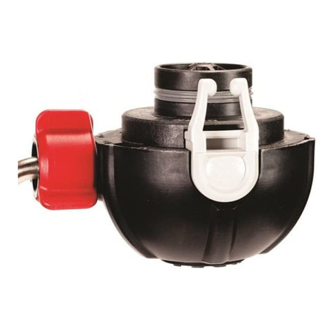
  9. MSA 10033170 User manual

MSA 10033170 User manual

Combination
Breathing
Apparatus
and
SECOND STAGE REGULATOR
TAL 502 (L) Rev. 0 © MSA 2005 Prnt. Spec. 10000005389 (I) Mat. 10064393
Doc. 10064393
2
TAL 502 (L) Rev. 0 - 10064393
Firehawk Second Stage Regulator Assembly
Second Stage w/Hose Ass'y Push-To-Connect
10033170 24" Front
10033171 42" Rear
10033172 Snap-Tite 42"
10033173 Snap-Tite 24"
Second Stage w/Hose Ass'y Slide
10033116 24" Front
10033117 42" Rear
10033118 Snap-Tite 42"
10033119 Snap-Tite 24"
Item Part No. Description
1697453 O-RING, FLUORSILICONE
2 634669 O-RING, SILICONE
310018540 DIAPHRAGM ASSEMBLY
410018547 UCLIP, (2 REQ'D)
510018622 RETAINER, SPRING (NOT USED WITH SOLID COVER)
610018774 KNOB, BYPASS
7 10018965 SPRING, QC, (2 REQ'D)
810018966 BODY, B YPASS
910018971 BYPASS INSERT ASSEMBLY
HOSE ASSEMBLY SECOND STAGE
10033174 FRONT 24" SNAP-TITE
10033175 REAR 42" SNAP-TITE
10033177 FRONT 24"
10033176 REAR 42"
1110020784 SCREEN, BYPASS
1210020931 SPRING, PD
1310023509 O-RING, VITON (2 REQ'D)
14 10023580 O-RING, SILICONE (2 REQ'D)
15 10024111 QC BUTTON ASSEMBLY
1610024112 SLIDEBUTTON ASSEMBLY
17 10030664 VALVE ASSEMBLY W/SHUTOFF
18 10026003 HOUSING, REGULATOR
19 10026139 COVER ASSEMBLY
19a 10047406 SOLID COVER
20 10031192 O-RING, SILICONE
10
14
13
TAL 502 (L) Rev. 0 - 10064393
3
12
18 18a
5
16 46811
3
15
13
14
7
1
9
24
7
19
17
10
604070 Lubricant
15
Airhawk Second Stage Regulator Assembly
part number 10037656 Push-To-Connect
*Note: Push-To-Connect Regulator Assemblies
have two (2) Quick-Connect Buttons (P/N 10024111) #15
*
Item P/N Description
1697453 O-Ring, Fluorsilicone
2634669 O-Ring, Silicone
310018540 Diaphragm Assembly
410018547 Uclip, (2 Req’d)
510018622 Retainer, Spring (not used with solid cover)
610018774 Knob, Bypass
710018965 Spring, QC, (2 Req’d)
810018966 Body, Bypass
910018971 Bypass Insert Assembly
1010020782 Hose Ass’y, 2nd Stg., Threaded
11 10020784 Screen, Bypass
12 10020931 Spring, PD
13 10023509 O-Ring, Viton (2 Req’d)
14 10037951 O-Ring (2 Req’d)
1510024111 QCButton Assembly
16 10030664 Valve Assembly w/Shutoff
17 10026003 Housing, Regulator
18 10026139 Cover Assembly
18a 10047406 Solid Cover
19 10031192 O-Ring
4
TAL 502 (L) Rev. 0 - 10064393
SECOND STAGE REGULATOR DISASSEMBLY
All repair procedures assume that the regulator is disas-
sembled from the apparatus and facepiece. To do this:
• Be sure the cylinder valve is completely closed.
• Disconnect the regulator from the facepiece.
• Be sure nothing is blocking the regulator outlet. Crack
the bypass valve to release any trapped air.
•If desired, disconnect the intermediate-pressure hose
from the first stage regulator at the hose fitting using a
11/16" open-end wrench. Refer to the INTRODUC-
TION Tab of this Binder for General Notes and
required tools.
Note: Refer to the appropriate illustrated parts lists for the
apparatus being repaired.
REMOVING THE REGULATOR COVER, SPRING, AND
SPRING RETAINER
1. Press and hold the
housing buttons IN.
Also, press the regula-
tor housing retaining
latches IN.
2. Pull firmly on the regu-
lator cover to remove
the cover, spring, and
spring retainer from the
regulator housing.
Note: Do not stretch the spring.
REMOVING THE SPRING AND SPRING RETAINER
1. Push the outside center (rubber) regulator cover IN.
Note: Do not pull the spring to remove the spring retainer.
2. Lift up on the spring
retainer to remove it
from the regulator
cover.
REMOVING THE SPRING FROM THE SPRING
RETAINER
1. Twist the spring clockwise to remove it from the spring
retainer.
Note: Do not stretch the spring.
REMOVING THE DIAPHRAGM
1. Roll the diaphragm edges out of the regulator housing
groove.
2. Slide the diaphragm away from the red bypass hand-
wheel and slide the diaphragm offthe valve fork.
DISASSEMBLING THE REGULATOR HOUSING O-RING
1. Remove the O-ring from regulator housing outlet. Be
careful not to scratch the O-ring groove.
DISASSEMBLING THE BYPASS AND HOSE W/SWIVEL
1. Remove the regulator cover,spring, and spring retainer.
Note: DO NOT REMOVE THE DIAPHRAGM (option)
2. Use a small, flat-blade
screwdriver to remove
the U-clip from the reg-
ulator housing.
3. Remove the bypass and hose assembly from the reg-
ulator housing.
5TAL 502 (L) Rev. 0 - 10064393
SECOND STAGE REGULATOR DISASSEMBLY
4. Remove the red bypass
handwheel. Slide the
handwheel back off the
bypass body to reveal
the U-clip in the bypass
body.
5. Using a screwdriver,
remove the U clip from
the bypass body.
6. Remove the hose
assembly by pulling the
hose out of the bypass
body.
7. Remove the hose
assembly O-ring. Be
careful not to scratch
the O-ring groove.
8. Inspect the screen
inside the bypass body.
If dirty, all dirt and for-
eign matter must be
removed before reusing
the screen. If the
screen is damaged,
replace it. as follows:
a. Insert a small screwdriver into the small hole side of
the bypass body and push the screen out the large
hole side of the bypass body.
INSPECTION FOR THE VALVE FORK FOR PROPER
HEIGHT
• Press on the top of the valve fork assembly to ensure
the valve fork assembly moves up and down freely.
Note: All calibrations will be performed with the bypass
handwheel facing away and with the valve fork’sslots fac-
ing in.
Ensure the U-clip holding the bypass and hose assem-
bly in the regulator housing is not removed or lost.
Lever Height Gauge
Note: The raised cylinder with grooves represents accept-
able lever height range for valve fork assembly.
6
TAL 502 (L) Rev. 0 - 10064393
CAUTION
SECOND STAGE REGULATOR REASSEMBLY
INSPECTION/ADJUSTMENT
• Place the large base of the Lever Height Gauge on the
flat area of the valve assembly body under the valve
fork assembly.
• Insert the Lever Height Gauge between the fork’s slots
of the valve fork assembly. Slide Lever Height Gauge
back until the Lever Height Gauge is centered on the
valve fork assembly.
• The top surface of the valve fork should be anywhere
along the raised cylinder surface of the Lever Height
Gauge. Do not touch or exert pressure on the valve
fork for this measurement.
• Then, press on the top of the valve fork assembly to
ensure the valve fork assembly moves up and down
freely.
NORMAL VALVE FORK HEIGHT RANGE
The required valve fork
height range corresponds
tothe top surface of the
valve fork at any position
along the raised cylinder.
MAXIMUM VALVE FORK ALLOWABLE HEIGHT
The maximum valve fork
allowable height corre-
sponds to the valve fork
top surface being even
with the top edge of the
raised cylinder.
MINIMUM VALVE FORK ALLOWABLE HEIGHT
The minimum valve fork
allowable height corre-
sponds to the valve fork
top surface being even
with the bottom edge of
the raised cylinder.
7TAL 502 (L) Rev. 0 - 10064393
Valve Fork
Lever Height
Gauge
Raised
Cylinder Base
Lever
Adjuster Knob
(wheel)
RAISED CYLINDER
WITH GROOVE
BASE
Normal
Height
Maximum
Height
Minimum
Allowable
Height
SECOND STAGE REGULATOR REASSEMBLY
ADJUSTING THE VALVE FORK HEIGHT FOR PROPER
PERFORMANCE
Note: All calibrations will be performed with the bypass
handwheel facing away and with the valve fork’s slots fac-
ing in. The regulator must be depressurized.
Ensure the U-clip holding the bypass and hose assem-
bly in the regulator housing is not removed or lost.
ADJUSTMENT FOR VALVE FORK MAXIMUM RANGE
Note: Clockwise rotation of the lever adjuster knob
(wheel) lowers the lever fork.
Note: All calibrations will be performed with the bypass
handwheel facing away and with the valve fork’sslots fac-
ing in.
Ensure the U-clip holding the bypass and hose assem-
bly in the regulator housing is not removed or lost.
•Press on the top of the valve fork assembly to ensure
the valve fork assembly moves up and down freely.
• Place a jeweler’s screwdriver on the flats of the lever
adjuster knob.
• Turn the lever adjuster knob (wheel) clockwise to lower
the valve fork. Be certain adjuster knob clicks into
position.
• The top surface of the valve fork should be along the
grooved surface of the lever height gauge without
exerting pressure on the valve fork assembly for nor-
mal valve fork height.
ADJUSTMENT FOR VALVE FORK MINIMUM RANGE
Note: Counter-clockwise rotation of lever adjuster knob
(wheel) raises the lever fork.
Note: All calibrations will be performed with the bypass
handwheel facing out.
Check that the U-clip holding bypass and hose
assembly in the regulator housing is properly
engaged. Pull on the bypass and hose assembly to
ensure that the bypass and hose assembly are secure-
ly attached to the regulator housing with the U-clip.
• Press on the top of the valve fork assembly to ensure
the valve fork assembly moves up and down freely.
• Place a jeweler’s screwdriver on the flats of the lever
adjuster knob.
• Turn the lever adjuster knob counter-clockwise to
raise the valve fork. Be certain adjuster knob clicks
into position.
• The top of the valve fork should be along the grooved
surface of the Lever Height Gauge without exerting
pressureon the valve fork assembly for normal valve
fork height.
•Press on the top of the valve fork assembly to ensure
the valve fork assembly moves up and down freely.
DISASSEMBLING THE VALVE ASSEMBLY
1. Remove the regulator cover, spring, and spring retainer.
2. Remove the diaphragm.
3. Remove the U-clip from the regulator housing.
Note: Use the bypass body as a tool to remove the
bypass insert.
8
TAL 502 (L) Rev. 0 - 10064393
Lever
Adjuster Knob
(wheel)
SECOND STAGE REGULATOR REASSEMBLY
4. Insert the bypass body
into the regulator hous-
ing bypass port.
5. Turn the valve counter-clockwise to unthread the
bypass insert from the valve.
6. Turnthe regulator hous-
ing until the bypass
insert drops out of the
regulator housing.
7. To remove the valve,
turnthe regulator hous-
ing upside down, or lift
the valve out of the
regulator housing.
8. Replace all O-rings on the bypass insert and bypass
body.
DISASSEMBLING THE REGULATOR HOUSING QC
BUTTON AND SLIDE BUTTON
1. Remove the old O-
rings. Be careful not to
damage the O-ring seal
area.
2. Pull on the buttons to remove them from the regulator
housing. Be careful not to lose the spring.
REASSEMBLING THE DIAPHRAGM
1. Slide the diaphragm
knob into the valve fork
slot, then slide the
diaphragm toward the
red bypass handwheel.
2. Roll the diaphragm edges over the regulator housing
groove.
Removing Spring from Spring Retainer
1. Twist spring (clockwise) out of spring retainer.
Note: Do not stretch the spring
Removing Diaphragm Assembly
1. Roll diaphragm edges out of regulator housing groove.
2. Slide diaphragm away from red bypass handwheel
and slide the diaphragm offthe valve fork.
9TAL 502 (L) Rev. 0 - 10064393
SECOND STAGE REGULATOR REASSEMBLY
INSTALLATION
Installing Spring into the New Solid Regulator Cover
Note: New Solid Regulator Cover does not use a spring
retainer.
1. Insert old spring into
solid cover
a. Sliding spring over finger, insert spring and finger
into the inside of solid cover.
2. Attach last coil of spring over the cover’shooks
a. Holding the spring
centered in the solid
cover with finger,
insertthumb of other
hand down along the
inside of cover to the
bottom of spring.
b. Slip the last coil of spring over each of the three (3)
molded hooks at the bottom of cover.
c. Ensure that the last
coil of the spring is
engaged over each
of the three (3) mold-
ed hooks.
Double check proper engagement of solid cover
spring by lifting on spring to ensure that the spring is
securely attached to the regulator cover.Do not
stretch the spring. Failure to follow this warning may
result in serious personal injury or death.
3. Push regulator cover and spring onto regulator hous-
ing.
Double check proper engagement by lifting on regula-
tor cover to ensure that the regulator cover is securely
attached to the regulator housing. Failure to follow
this warning may result in serious personal injury or
death.
REASSEMBLING THE REGULATOR COVER
1. To install the spring in the retainer, press the spring’s
last coil over the retainer hooks.
2. Push the spring retainer over the regulator cover cen-
ter stem.
3. Lift the spring retainer to check that the spring and
retainer are engaged properly.
4. Push the regulator cover, spring, and spring retainer
on the regulator housing.
Pull on the regulator cover to be surethe regulator
cover and regulator housing are secure.
REASSEMBLING THE REGULATOR HOUSING O-RING
1. Apply a light film of Christo-Lube lubricant to the new
O-ring.
2. Roll the new O-ring over the end of the regulator
housing outlet and seat it into the O-ring groove. If the
O-ring is not seated, it can cause an air leak.
REASSEMBLING THE BYPASS AND HOSE ASSEMBLY
1. Apply a light film of Christo-Lube lubricant to all O-
rings.
2. Roll a new O-ring into the first groove of the bypass
body.
3. Insert the new screen (if removed). Insert screen into
the large hole (hose swivel) side of the bypass body.
Be careful not to damage the screen. Make sure the
screen is flat inside the body.
10
TAL 502 (L) Rev. 0 - 10064393
SECOND STAGE REGULATOR REASSEMBLY
4. Roll a new O-ring into
the first groove of the
hose swivel.
5. Insert the swivel into
the bypass body.
Slide the U-clip through
the bypass body.The
U-clip should slide
through the bypass
body freely.
6. Slide the red bypass
handwheel over the
bypass body. The
handwheel hex lines up
with the handwheel.
7. Ensurethat the hose with swivel moves freely.
8. Insert the bypass body
and hose assembly
into the regulator hous-
ing so that the bypass
body tabs are lined up
with the slots in the
bypass insert.
9. Slide the U clip through
the regulator housing.
The U-clip should slide
through the regulator
housing freely.
REASSEMBLING THE VALVE ASSEMBLY
1. Insert the valve into the regulator housing -- valve fork
slot facing up and away from the bypass port.
2. Push the valve into the regulator housing.
3. Insertthe bypass insert
into the bypass port --
slot facing out.
4. Use the bypass body to thread the bypass insert into
the valve. Hand-tighten only.
Note: If the bypass insert does not thread into valve
assembly easily, the valve assembly is not aligned in the
regulator housing properly.Ensurethat the valve assembly
is fully seated in the regulator housing.
5. Insert the hose assembly and bypass body into the
regulator housing.
11 TAL 502 (L) Rev. 0 - 10064393
SECOND STAGE REGULATOR REASSEMBLY
6. Insert the U-clip into
the regulator housing.
7. Replace the diaphragm.
8. Replace the spring retainer, spring, and regulator
cover.
9. Check the valve assembly calibration. (See Inspection
for Valve Fork section.)
10. Flow-Test the SCBA (see the TESTER section of this
Binder).
REASSEMBLING THE REGULATOR HOUSING QC
BUTTON AND SLIDE BUTTONS
1. Apply a light film of Christo-Lube lubricant to the new
O-rings.
2. Install new O-rings on the button’s post.
Note: With the red bypass handwheel facing you and the
cap facing up, the slide button is to the left and the hous-
ing button is to the right.
3. Install the spring. Align the buttons.
4. Push firmly on the buttons, install the post O-ring on
the inside of the regulator housing.
5. Double-check proper engagement by pulling on the
buttons to ensure that they are securely attached to
the regulator.
12
TAL 502 (L) Rev. 0 - 10064393

Other manuals for 10033170

1

This manual suits for next models

7

Other MSA Controllers manuals

MSA PremAire System User manual

MSA

MSA PremAire System User manual

MSA Ultima Series User manual

MSA

MSA Ultima Series User manual

MSA 10033170 User manual

MSA

MSA 10033170 User manual

MSA Zero Two Series User manual

MSA

MSA Zero Two Series User manual

MSA GasGard XL Operating and maintenance instructions

MSA

MSA GasGard XL Operating and maintenance instructions

MSA GasGard XL User manual

MSA

MSA GasGard XL User manual

MSA ModCon 75 User manual

MSA

MSA ModCon 75 User manual

MSA FireHawk M7 Setup guide

MSA

MSA FireHawk M7 Setup guide

MSA Firehawk Responder Series Operating instructions

MSA

MSA Firehawk Responder Series Operating instructions

MSA BVC-650 User manual

MSA

MSA BVC-650 User manual

MSA Firehawk 10043892 Setup guide

MSA

MSA Firehawk 10043892 Setup guide

MSA Ultima Series User manual

MSA

MSA Ultima Series User manual

MSA SENTRY io User manual

MSA

MSA SENTRY io User manual

MSA SUPREMA Touch Installation and operating instructions

MSA

MSA SUPREMA Touch Installation and operating instructions

MSA SMC Sentry-IT NEMA Retrofit Kit User manual

MSA

MSA SMC Sentry-IT NEMA Retrofit Kit User manual

MSA GasGard XL User manual

MSA

MSA GasGard XL User manual

MSA General Motions MC600 User manual

MSA

MSA General Motions MC600 User manual

MSA ZGARD CX II User manual

MSA

MSA ZGARD CX II User manual

MSA Ultima User manual

MSA

MSA Ultima User manual

MSA M1 User manual

MSA

MSA M1 User manual

MSA ZGARD C User manual

MSA

MSA ZGARD C User manual

Popular Controllers manuals by other brands

Integra CALEC ST III Standard installation manual

Integra

Integra CALEC ST III Standard installation manual

Viconics COV-PIR-FCU-C-5000 install guide

Viconics

Viconics COV-PIR-FCU-C-5000 install guide

Modellbau-Regler AS-12/15RW user manual

Modellbau-Regler

Modellbau-Regler AS-12/15RW user manual

YASKAWA 264IF-01 user manual

YASKAWA

YASKAWA 264IF-01 user manual

TECALEMIT TC100D2 manual

TECALEMIT

TECALEMIT TC100D2 manual

M-Audio Keystation manual 

M-Audio

M-Audio Keystation manual 

Martinsound MonitorMAX user manual

Martinsound

Martinsound MonitorMAX user manual

Shimaden SR23 series quick reference

Shimaden

Shimaden SR23 series quick reference

Stober SR6 Commissioning instructions

Stober

Stober SR6 Commissioning instructions

RTMOTION MK3 user guide

RTMOTION

RTMOTION MK3 user guide

GE Mooney Flowgrid instruction manual

GE

GE Mooney Flowgrid instruction manual

VocoPro KC-300 PRO owner's manual

VocoPro

VocoPro KC-300 PRO owner's manual

National Instruments cRIO-9031 user manual

National Instruments

National Instruments cRIO-9031 user manual

Verasys LC-VAC300 0 Series installation instructions

Verasys

Verasys LC-VAC300 0 Series installation instructions

Lenz DIGITAL plus LZ100 Information

Lenz

Lenz DIGITAL plus LZ100 Information

Panasonic TY-TP10W operating instructions

Panasonic

Panasonic TY-TP10W operating instructions

B+B WLS-GEH230V Operation manual

B+B

B+B WLS-GEH230V Operation manual

PI N-472 user manual

PI

PI N-472 user manual

manuals.online logo
manuals.online logoBrands
  • About & Mission
  • Contact us
  • Privacy Policy
  • Terms and Conditions

Copyright 2025 Manuals.Online. All Rights Reserved.