Model 4802A
iv
List of Figures
Figure 1: Control Module Coding Strip ...................................................................................................ix
Figure 2: Wire Strip Length .................................................................................................................. x
Figure 3: Rear Terminal Designations.................................................................................................... x
Figure 4: Sensor/Controller Connections................................................................................................xi
Figure 5: Rear Power Connections.......................................................................................................xii
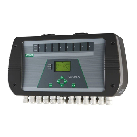
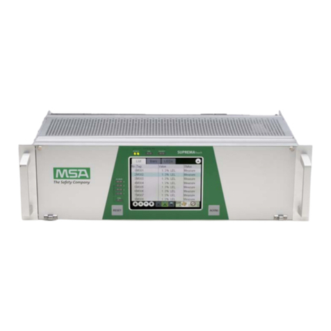
Figure 6: Model 4802A ........................................................................................................................ 1
Figure 7: Control Module Coding Strip ................................................................................................... 4
Figure 8: Wire Strip Length .................................................................................................................. 5
Figure 9: Rear Terminal Designations.................................................................................................... 5
Figure 10: Recommended Relay Protection Circuits ................................................................................ 7
Figure 11: Open Collector External Circ uit s ............................................................................................ 8
Figure 12: Sensor/Controller Connections .............................................................................................. 9
Figure 13: Switch Connections for Card Test Feature............................................................................... 9
Figure 14: Analog Signal Connections ..................................................................................................10
Figure 15: Power Connections.............................................................................................................11
Figure 16: Front Panel Display ............................................................................................................19
Figure 17: Portable Purge Calibrator ....................................................................................................20
Figure 18: Entering CAL Check Mode...................................................................................................20
Figure 19: Portable Purge Calibrator ....................................................................................................22
Figure 20: Entering CAL Mode ............................................................................................................22
Figure 21: AC Display during CAL Mode...............................................................................................23
Figure 22: CP Display during CAL Mode...............................................................................................23
Figure 23: CC Display during CAL Mode...............................................................................................24
Figure 24: F7 Display during CAL Mode................................................................................................24
Figure 25: Entering Setup and Setup Check Modes................................................................................26
Figure 26: Entering the Password ........................................................................................................27
Figure 27: Entering Inhibit Mode..........................................................................................................27
Figure 28: Energized/De-Energized Alarm Option...................................................................................28
Figure 29: A2 Latching/Non-Latching Alarm Option.................................................................................28
Figure 30: A2 Alarm Set Point Option...................................................................................................29
Figure 31: A1 Energized-De-Energized Alarm Option..............................................................................30
Figure 32: A1 Latching/Non-Latching Alarm Option.................................................................................30
Figure 33: A1 Set Point Option............................................................................................................31
Figure 34: Calibration Level ................................................................................................................31
Figure 35: Fault / Inhibit Option............................................................................................................32
Figure 36: Entering Card Test Options..................................................................................................32
Figure 37: Card Test Ramp Time.........................................................................................................33
Figure 38: Alarm Output during a Card Test...........................................................................................33
Figure 39: Password Enabled/Disabled Option.......................................................................................34
Figure 40: Entering A New Password ...................................................................................................35
Figure 41: Catalytic Sensor Diagram ....................................................................................................38
Figure 42: Universal Sensor Housing with Sensor and Splash-Guard ........................................................40
Figure 43: Splash-Guard Picture..........................................................................................................40
Figure 44: Dust Guard Picture.............................................................................................................41
Figure 45: Dust Guard Assemb ly Kit Picture ..........................................................................................41
Figure 46: Duct Mounting Plate, Assembly Drawing................................................................................42
Figure 47: Portable Purge Calibrator ....................................................................................................43
Figure 48: 3-Liter Chamber.................................................................................................................43
Figure 49: Outline and Terminal Connections 4802A...............................................................................53
Figure 50: Final Assembly, 4802A........................................................................................................54

