MSI MS-7204 User manual

i
MS-7204(v1.XmBTXMainboard)
945PSeries

ii
ManualRev:1.0
ReleaseDate:October2005
FCC-BRadioFrequencyInterferenceStatement
Thisequipment hasbeen testedandfoundtocomplywiththelimitsforaclassB
digital device,pursuanttopart15ofthe FCCrules.Theselimitsaredesigned to
providereasonableprotection againstharmful interferencewhentheequipmentis
operated inacommercial environment.Thisequipmentgenerates,usesandcan
radiateradiofrequencyenergyand,if notinstalledand usedinaccordancewiththe
instructionmanual,maycauseharmfulinterferencetoradiocommunications.Operation
ofthisequipment in aresidentialarea islikelytocauseharmful interference, inwhich
casetheuserwill berequiredtocorrecttheinterferenceathisownexpense.
Notice1
Thechangesormodificationsnotexpresslyapprovedbythepartyresponsiblefor
compliancecould void theuser sauthoritytooperatetheequipment.
Notice2
Shielded interfacecablesandA.C.powercord,if any,mustbeusedin orderto
complywiththeemissionlimits.
VOIRLANOTICED INSTALLATIONAVANT DERACCORDERAURESEAU.
Micro-StarInternational
MS-7204
ThisdevicecomplieswithPart15oftheFCCRules.Operationissubjecttothe
followingtwoconditions:
(1)thisdevicemaynotcauseharmful interference,and
(2)thisdevicemustacceptanyinterferencereceived,includinginterferencethat
maycauseundesiredoperation

iii
CopyrightNotice
The materialin thisdocumentistheintellectualpropertyof MICRO-STAR
INTERNATIONAL.Wetakeeverycarein thepreparationof thisdocument, butno
guaranteeisgivenastothe correctness of itscontents.Ourproductsareunder
continualimprovementand wereservetherighttomakechangeswithoutnotice.
Trademarks
Alltrademarksarethepropertiesoftheirrespectiveowners.
AMD,Athlon™,Athlon™XP,Thoroughbred™,andDuron™areregistered trade-
marksofAMDCorporation.
Intel®andPentium®areregisteredtrademarksofIntelCorporation.
PS/2and OS®/2areregistered trademarks of InternationalBusinessMachines
Corporation.
Microsoftisaregistered trademarkofMicrosoft Corporation.Windows®98/2000/NT/
XPareregistered trademarks ofMicrosoftCorporation.
NVIDIA, theNVIDIAlogo,DualNet,and nForceareregisteredtrademarksortrade-
marksof NVIDIACorporationin theUnitedStatesand/orothercountries.
Netware®isaregisteredtrademarkofNovell,Inc.
Award®isaregisteredtrademarkofPhoenixTechnologiesLtd.
AMI®isaregistered trademarkofAmerican MegatrendsInc.
Kensingtonand MicroSaverareregistered trademarks of theKensingtonTechnology
Group.
PCMCIAand CardBusareregisteredtrademarks of thePersonalComputerMemory
CardInternationalAssociation.
TechnicalSupport
Ifaproblemariseswithyoursystemandnosolutioncanbeobtainedfromtheuser s
manual,pleasecontactyourplaceofpurchaseorlocal distributor.Alternatively,
pleasetrythefollowinghelp resourcesforfurtherguidance.
†VisittheMSIhomepage &FAQsitefortechnical guide,BIOSupdates,driver
updates,and otherinformation: http://www.msi.com.tw & http://www.msi.
com.tw/program/service/faq/faq/esc_faq_list.php
†Contactourtechnicalstaffat: support@msi.com.tw
RevisionHistory
Revision RevisionHistory Date
V1.0 FirstreleaseforPCB1.X October2005
withIntel945P&ICH7/ICH7R

iv
1. Alwaysread thesafetyinstructionscarefully.
2. KeepthisUser sManualforfuturereference.
3. Keepthisequipmentawayfromhumidity.
4. Laythisequipmentonareliableflatsurfacebeforesetting itup.
5. Theopeningsontheenclosureareforairconvectionhenceprotectstheequip-
mentfromoverheating.Donotcovertheopenings.
6. Makesurethevoltageofthe powersourceand adjust properly110/220Vbe-
foreconnectingtheequipmenttothepowerinlet.
7. Placethepowercordsuchawaythatpeoplecannotstepon it. Donotplace
anythingoverthepowercord.
8. AlwaysUnplugthe PowerCordbeforeinsertinganyadd-on cardormodule.
9. All cautionsand warningsontheequipmentshouldbenoted.
10. Neverpouranyliquidintotheopeningthatcoulddamageorcauseelectrical
shock.
11. If anyof thefollowing situationsarises, gettheequipmentcheckedbyaservice
personnel:
†Thepowercordorplug isdamaged.
†Liquidhaspenetratedintotheequipment.
†Theequipmenthasbeenexposedtomoisture.
†Theequipment hasnot workwell oryoucannotget itworkaccording to
User sManual.
†Theequipmenthasdroppedanddamaged.
†Theequipmenthasobvioussign of breakage.
12.Donotleavethisequipmentin anenvironmentunconditioned,storage
temperatureabove 600 C(1400F),itmay damagetheequipment.
SafetyInstructions
CAUTION:Dangerofexplosionifbatteryisincorrectlyreplaced.
Replaceonlywiththesameorequivalenttyperecommended bythe
manufacturer.

v
WEEE Statement

vi

vii

viii
CONTENTS
FCC-B RadioFrequencyInterferenceStatement..........................................................ii
CopyrightNotice..............................................................................................................iii
TechnicalSupport...........................................................................................................iii
RevisionHistory..............................................................................................................iii
SafetyInstructions.........................................................................................................iv
WEEE Statement..............................................................................................................v
Chapter1.GettingStarted....................................................................................1-1
MainboardSpecifications...................................................................................1-2
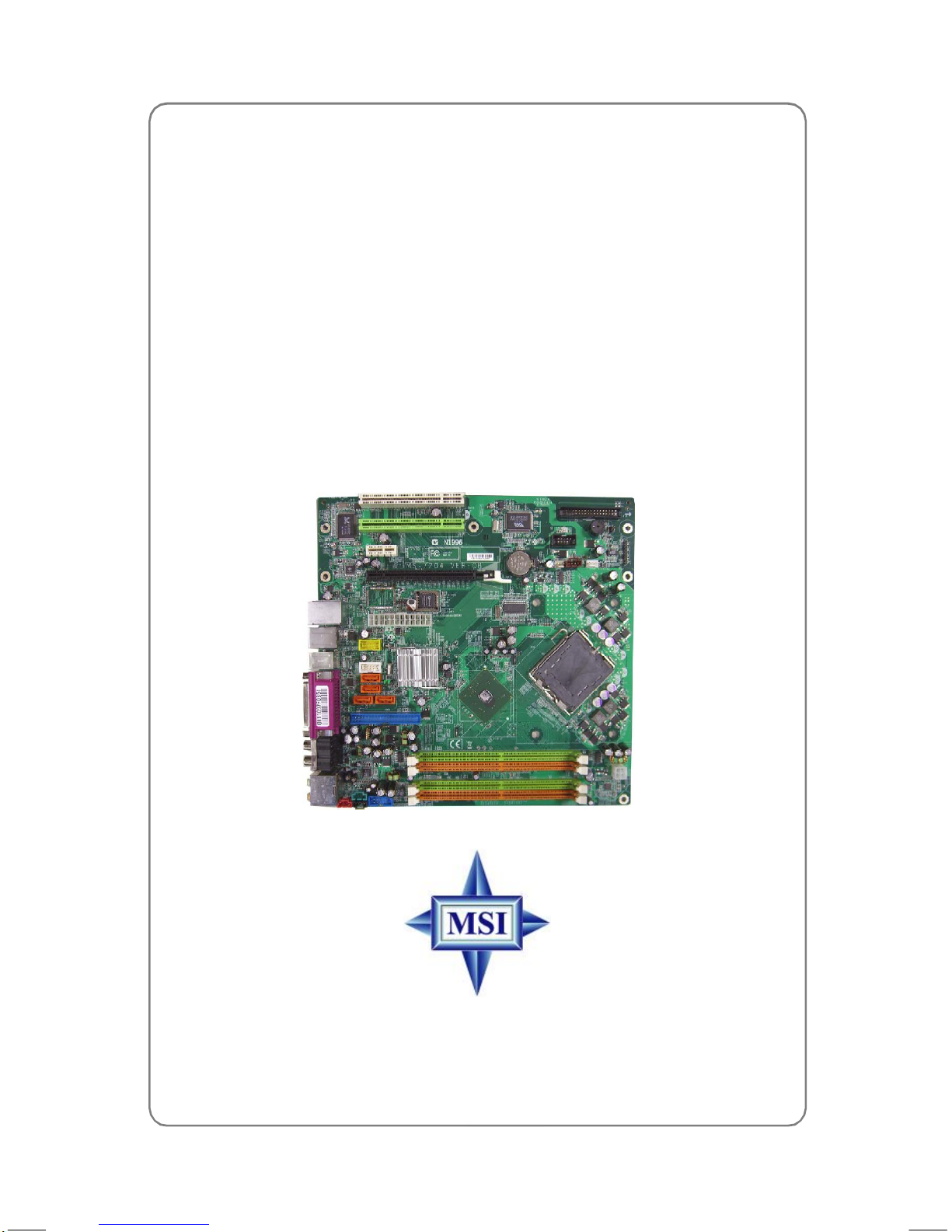
MainboardLayout................................................................................................1-4
Packing Contents.................................................................................................1-5
Chapter2.HardwareSetup..................................................................................2-1
Quick ComponentsGuide...................................................................................2-2
Central ProcessingUnit:CPU.............................................................................2-3
IntroductiontoLGA775CPU......................................................................2-3
CPU&CoolerInstallation.............................................................................2-4
Memory.................................................................................................................2-7
IntroductiontoDDR2SDRAM.....................................................................2-7
MemoryModule PopulationRules...............................................................2-7
Installing DDR2Modules..............................................................................2-8
PowerSupply......................................................................................................2-9
BTX24-Pin PowerConnector:BTX1.........................................................2-9
BTX12VPowerConnector:JPWR1..........................................................2-9
BackPanel.........................................................................................................2-10
Mouse/KeyboardConnector....................................................................2-10
IEEE 1394 Port............................................................................................2-10
Serial PortConnector:COMPort...............................................................2-11
USBConnectors.........................................................................................2-11
LAN(RJ-45)Jack......................................................................................2-12
AudioPortConnectors..............................................................................2-12
ParallelPortConnector:LPT1...................................................................2-13
Connectors........................................................................................................2-14
FloppyDiskDriveConnector:FDD1........................................................2-14
Fan PowerConnectors:CPUFAN1/SYS_FAN1......................................2-14
HardDiskConnector:IDE1.......................................................................2-15
FWH/LPCDebugging Pin Header:JLPC1.................................................2-15

ix
SerialATAConnectorscontrolledbyIntel ICH7:SATA1~SATA4...........2-16
Video-InConnector:JVID1.......................................................................2-17
FrontLine-InConnector:JL_IN1.............................................................2-17
SCARTOutputConnector:JSCA1.........................................................2-17
FrontLCD ModukeHeader:JFLCD........................................................2-18
FrontPanelConnectors: JF_P1................................................................2-18
FrontUSBConnectors:JUSB1/JUSB2..................................................2-19
FrontPanelAudioConnector:JAUD1......................................................2-19
IEEE1394Connector: JFW1(Optional)...................................................2-20
Jumpers..............................................................................................................2-21
ClearCMOSJumper:JBAT1.....................................................................2-21
Slots....................................................................................................................2-22
PCIExpressSlots(optional).....................................................................2-22
PCI(PeripheralComponent Interconnect)Slots......................................2-23

1-1
GettingStarted
Chapter1.Getting
Started
Thankyouforchoosing the 945PSeries (MS-7204)v1.x
mBTXmainboard.The 945PSeries mainboardisbasedon Intel®
945P and Intel®ICH7/ICH7R chipset foroptimalsystemefficiency.
Designed tofit theadvanced Intel®Pentium4PrescottLGA775
processor,the 945PSeries mainboarddeliversahigh performance
and professionaldesktopplatformsolution.
GettingStarted

1-2
MS-7204 mBTXMainboard
MainboardSpecifications
CPU
†SupportsIntel®Pentium4/CeleronDPrescott LGA775 processors(Prescott
and Smithfield)inLGA775 package.
†Supports2005PerformanceFMBCPUVRDesign.
†Supports3/4pin CPUFan Pin-HeaderwithFanSpeedControl.
†Supportsup toPentium43XX, 5XX,6XX&8XX (Prescott andSmithfield)
Chipset
†Intel®945Pchipset
-SupportsFSB533/800/1066MHz.
-SupportsPCIExpress x16 graphicsinterface.
-SupportsDDR2533/667
†Intel®ICH7/ICH7Rchipset(optional)
-Hi-SpeedUSB (USB2.0)controller, 480Mb/sec,up to8ports.
-4SATAII portswithtransferrateup to3Gb/s.
-1channel UltraATA100busMasterIDEcontroller.
-PCI Masterv2.3, I/OAPIC.
-ACPI 2.0Compliant.
-Serial ATARAID0,RAID1, RAID10,RAID5and MatrixRAID. (forICH7R)
-IntegratedAHCIcontroller(ICH7R).
Main Memory
†SupportsfourunbufferedDIMM of 1.8VoltDDR2SDRAM
†Supportsup to4GBmemorysize.
†SupportsDualchannelDDRmemoryarchitecture.
†SupportsDDR2533/667 memoryinterface.
Slots
†One PCI Expressx16slot.
†OnePCIExpress x1slots.
†Two32-bitv2.3MasterPCIbusslots(support3.3v/5vPCIbusinterface).
†Thesecond PCIslot(PCI2.2, in greencolor) supports3devices.
On-BoardIDE
†OneUltraDMA66/100IDEcontrollersintegrated in ICH7/ICH7R.
-SupportsPIO, BusMasteroperationmodes.
†SATAII controllerintegratedinICH7/ICH7R.
-Upto300MB/sectransferspeed.
-Canconnectup tofourSATAIIdevices.
-SupportsAHCIcontrollerwithSATARaid0,Raid1andMatrixRaid(ICH7R).
On-BoardPeripherals
†On-BoardPeripheralsinclude:
-1floppyportsupports1FDDwith360K,720K,1.2M, 1.44Mand2.88Mbytes
-1serialport
-1parallelportsupportsSPP/EPP/ECPmode
-1Line-In/Front-Out/SideSurround / CenterBass / BackSurround

1-3
GettingStarted
-1coaxialSPDIF-Out / SPDIF-In/ OpticalSPDIF-Out /SPDIF-In
-8USBports(Rear*4/Front *4)
-1RJ-45LANjack
LAN
†Intel 8100C
-Supports10/100 Mb/s.
1394(optional)
†SupportstwoIEEE1394 onboardpinheader.Transferrateisup to400Mbps.
†ControlledbyVIAVT6307 chip.
Audio
†HighDefinitionlinkcontrollerintegratedinIntel®ICH7/ICH7Rchip.
†7.1+2channelsaudiocodecRealtekALC882.
-CompliantwithAzalia 1.0Spec.
BIOS
†ThemainboardBIOSprovides “Plug&Play”BIOSwhichdetectstheperiph-
eral devicesand expansioncardsoftheboardautomatically.
†ThemainboardprovidesaDesktopManagementInterface(DMI)functionwhich
recordsyourmainboardspecifications.
Mountingand Dimension
†mBTXFormFactor:26.7cmx26.5cm
†7mounting holes

1-4
MS-7204 mBTXMainboard
MainboardLayout
945PSeries(MS-7204)v1.xmBTXMainboard
BATT
+
VIA
VT6307
RTL8100C
Intel945P
B
I
O
S
IDE1
JVID1JAUD1
JPWR1
SYS_FAN1
CPUFAN1 JF_P1
JFLCD
FDD1
JFW1 J3
JL_IN1
ALC882
JSCA1
SATA1
JUSB2
BTX1
PCI_E2
PCI_E1
DIMM1
DIMM3
DIMM2
DIMM4
PCI1
PCI2
JLPC1
JUSB1
JBAT1
SATA2
SATA3 SATA4
Top:mouse
Bottom:keyboard
Top:
ParallelPort
Bottom:
COMA
T:SPDIF-IN
B:OPT-In
T:SPDIF-Out
B:OPT-Out
Front-Out
SS-Out
Line-In
CS-Out
BS-Out
Top: LANJack
Bottom:USBports
Top:1394port
B:USBports
Intel
ICH7/ ICH7R

2-1
HardwareSetup
Chapter2. HardwareSetup
ThischaptertellsyouhowtoinstalltheCPU,memorymodules,
and expansioncards,aswell ashowtosetupthejumpersonthe
mainboard.Also,itprovidestheinstructionsonconnecting theperiph-
eral devices, suchasthemouse,keyboard,etc.
Whiledoing theinstallation,becarefulinholdingthecompo-
nentsand followthe installationprocedures.
HardwareSetup

2-2
MS-7204mBTXMainboard
Quick ComponentsGuide
JFW1,
p.2-20
CPUFAN1,
SYS_FAN1,
p.2-14
JF_P1,
p.2-18
JPWR1,
p.2-9
IDE1,
p.2-15
JBAT1,
p.2-21
CPU,
p.2-3
BTX1,
p.2-9
DDR2DIMMs,
p.2-7
JVID1,
p.2-17 JAUD1,
p.2-19
JL_IN1,
p.2-17
SATA1~SATA4,
p.2-16
BackPanel
I/O, p.2-10
JSCA1,
p.2-17
FDD1, p.2-14
PCISlots1~2,
p.2-23
JUSB1/2,
p.2-19
PCI-ESlots,
p.2-22
JLPC1,
p.2-15
JFLCD,
p.2-18

2-3
HardwareSetup
Central ProcessingUnit:CPU
ThemainboardsupportsIntel®Pentium4Prescott processor.Themainboard
usesaCPUsocketcalledLGA775.Whenyou areinstalling theCPU, make sureto
installthecoolertopreventoverheating. If you do nothavetheCPUcooler,
contactyourdealertopurchaseand install thembeforeturningonthecomputer.
ForthelatestinformationaboutCPU,pleasevisit http://www.msi.com.tw/
program/products/mainboard/mbd/pro_mbd_cpu_support.php.
MSIRemindsYou...
Overheating
Overheatingwill seriouslydamagethe CPUand system, always make
surethecoolingfancanworkproperlytoprotectthe CPUfrom
overheating.
Replacing theCPU
While replacing theCPU,alwaysturnoffthe ATXpowersupplyor
unplugthepowersupply spowercordfromgroundedoutletfirstto
ensurethe safetyofCPU.
Overclocking
Thismotherboardisdesignedtosupportoverclocking. However,please
makesureyourcomponentsareabletotoleratesuchabnormal setting,
whiledoing overclocking.Anyattempttooperatebeyondproductspeci-
ficationsisnotrecommended. Wedonotguaranteethedamages
orriskscausedbyinadequateoperationorbeyondproduct
specifications.
Introduction toLGA775 CPU
The surfaceof LGA775CPU.
Remembertoapplysomesili-
coneheattransfercompound on
itforbetterheatdispersion.
Yellowtriangleis the Pin1indicator
Thepin-padsideofLGA775
CPU.
Yellowtriangleis the Pin1indicator
Alignment Key Alignment Key

2-4
MS-7204mBTXMainboard
CPU&Cooler Installation
Whenyou areinstalling theCPU, make suretheCPUhas acoolerat-
tachedon thetop topreventoverheating. If youdonothavethecooler,contact
yourdealertopurchaseand install thembeforeturningonthecomputer.Meanwhile,
donotforgettoapplysomesiliconheat transfercompound onCPUbeforeinstalling
the heatsink/coolerfanforbetterheatdispersion.
FollowthestepsbelowtoinstalltheCPU&coolercorrectly.Wrong installation
will causethedamageof yourCPU&mainboard.
1.TheCPUhasalandsidecoveronthe
bottomtoprotecttheCPUcontactfrom
damage.Rotateittomakethepin1
indicator(yellowtriangle)intheright-
bottomcorner.
2.Takeouttheaccompanying CPUClip
androtateitforthesamedirection
asthe CPU(Pin1indicatorisinthe
left-bottomcorner).
land sidecover
MSIRemindsYou...
1.ConfirmifyourCPUcoolerisfirmlyinstalledbeforeturningon your
system.
2.Donottouchthe CPUsocketpinstoavoiddamaging.
3.The availabilityoftheCPUland side coverdependsonyourCPU
packing.
3.Use2handstoremovethe land side
cover(if any).Pleasenotenot totouch
thepins.
4.Alignthetwopin1indicators(the
trianglesontheCPU&theCPUClip),
andusetheCPUClip toclip theCPU
up,pressing theclipsonbothsides
tothecenter,asthearrowsshown.

2-5
HardwareSetup
5.TheCPUhasaplasticcaponitto
protectthecontactfromdamage.
Beforeyou haveinstalledtheCPU,
alwayscoverittoprotectthesocket
pin.
6.Removethecapfromleverhingeside
(asthearrowshows).Thepinsof
socketreveal.
7.Lift the loadleverupand openthe
loadplate.
8.CorrectlyalignthetriangleofCPUClip
withthe CPUchamfer,andthesquare
on theCPUCliptothehookofthe
socket.
9.Useyourthumbandthemiddlefin-
gerstopushtheclipstoreleasethe
CPU,thenpressdowntheCPUwith
yourindexfingertoallowthewhole
module tobe installedontotheCPU
socket.
10.TheCPUisinstalledwell on theCPU
socket.

2-6
MS-7204mBTXMainboard
12.Press downtheloadleverlightly
ontotheloadplate,and thensecure
theleverwiththehookunderreten-
tiontab.
11.Visuallyinspectif theCPUisseated
wellintothesocket, thenremovethe
CPUClip with2fingers.Thencover
theloadplateontothepackage.
13.Positionthemainboardintothechas-
sisandusethe retainingscrewsto
secureitintothe place.Thenalign
the holesonthe mainboardandchas-
siswiththe cooler.
Holeson case
Holesonmainboard
14.Putdownthecoolerand usethe
retaining screwsof the coolertose-
cureitintotheplace.Makesurethe
coolerisintheproperorientation,the
coolerwill onlyfitin the right
orientation.(Pleasereferthepictures
below.)
Thefan ofthecooler.
MSIRemindsYou...
1.Check theinformationin PCHealthStatus of H/WMonitor in BIOS
(Chapter3)fortheCPUtemperature.
2.WheneverCPUisnotinstalled,always protectyourCPUsocketpin
withthe plasticcap covered (showninFigure1)toavoiddamaging.
3.Pleasenotethatthe mating/unmating durabilityof theCPUis20 cycles.
Thereforewesuggestyou do notplug/unplug the CPUtoo often.

2-7
HardwareSetup
Memory
Themainboardprovides4slotsfor240-pin DDR2DIMM, whichsupportsthe
memorysizeup to4GB.
SinceDDR2modulesarenot interchangeablewithDDR1and the DDR2stand-
ardisnotbackwardcompatible,youshould alwaysinstall DDR2memorymodulein
theDDR2slot(DIMM1~DIMM4). Otherwise,you arenotabletobootup yoursystem
and yourmainboardmightbedamaged.
Fortheupdatedsupportingmemorymodules,pleasevisit http://www.msi.
com.tw/program/products/mainboard/mbd/pro_mbd_trp_list.php.
Introduction toDDR2SDRAM
DDR2isanewtechnologyofmemorymodule, and itsspeed isthe toplimit of
currentDDR1technology.DDR2usesa1.8Vsupplyforcoreand I/Ovoltage,com-
paredto2.5VforDDR1,andrequires28% less powerthanDDR1chips.DDR2truly
isthe futureof memory,butwillrequiresomechangesasthetechnologyisnot
backwardlycompatibleandonlymotherboardsspecificallydesignedforDDR2memory
willbeabletosupportthesechips.
DDR2incorporatesnewfeaturesatthechiplevelthatgiveitbettersignal
integrity,therebyenabling higherclockspeeds.
DDR2moduleshave240 pins,versus184 pinsonaDDR1module,and the
lengthofDDR2moduleis5.25”.DDR2moduleshavesmallerandtighterspaced pins.
The heightofDDR2modulesvaries,buttheywill typicallybelessthan1.3”in height.
Memory ModulePopulation Rules
Installat leastoneDIMMmodule on the slots.EachDIMMslot supportsup toa
maximumsizeof1GB.Userscan install eithersingle-ordouble-sidedmodulesto
meettheirownneeds.Pleasenotethat eachDIMMcanworkrespectivelyfor
single-channelDDR,whilebothchannels(indifferentcolor)populated
withsameamountofmemorysizewillworkas dual-channelDDR.
DIMM1~DIMM4
(fromToptobuttom
ChannelA(DIMM1&DIMM2)
Channel B(DIMM3&DIMM4)
This manual suits for next models
2
Table of contents
Other MSI Motherboard manuals

MSI
MSI MS-6380LE User manual

MSI
MSI MS-6791 User manual

MSI
MSI B350 PC MATE User manual

MSI
MSI 865G Neo2 User manual

MSI
MSI MICRO ATX EX7 User manual

MSI
MSI H81M-P32L User manual

MSI
MSI KM2M Combo User manual

MSI
MSI K9NGM4 Series User manual

MSI
MSI X299 GAMING PRO CARBON User manual

MSI
MSI MS-98F5 User manual

MSI
MSI MS-6330 User manual

MSI
MSI PRO H610M-E DDR4 User manual

MSI
MSI H170M BAZOOKA User manual

MSI
MSI PRO B760M-A WIFI DDR4 User manual

MSI
MSI B150A GAMING PRO User manual

MSI
MSI MAG B650 TOMAHAWK WIFI User manual

MSI
MSI MS-7222 User manual

MSI
MSI MEG Z490 ACE User manual

MSI
MSI MS-7358 User manual

MSI
MSI MS-9642 User manual