6
OPERATING INSTRUCTIONS
A.CONTROLS
1. Engine Choke
There are usually two moving levers on the side of
an engine near the carburetor. One of these is the
choke, the other is the throttle. The choke lever
should be moved all the way to the "CHOKE"
position when starting a cold engine. After the
engine starts, slowly move the lever all the way
back to the "RUN" position as the engine warms
up. A warm engine should not be choked.
2. Engine Throttle
The second moving lever on the side of an engine
near the carburetor is the throttle. For starting,
place the lever at 50% of the maximum RPM. For
pump pressures up to about 100 psi, the throttle
should be set at 30% of the maximum RPM. For
maximum pressures, the throttle should be set at
"FAST" or 100% of the maximum RPM.
3. Ignition Switch
NOTE: Make sure the pump is not under
pressure before trying to start the engine.
a. Recoil-Start Engines
On some engines, moving the throttle lever to
"OFF" or "STOP", while the engine is running
will short out the magneto and stop the
engine. On other engines, a separate lever or
knob on the side or top of the engine functions
as an ignition switch. They have two positions:
"OFF" and "START". They must be placed in
the "START" position before trying to start the
engine. Moving the lever or turning the knob
back to the "OFF" position while the engine is
running will short out the magneto and stop
the engine.
b. Electric-Start Engines
Automotive-type key switches are used as
ignition switches and are usually found on the
side or top of the engine. A clockwise 45° turn
closes the ignition circuit and turning the
switch further against spring pressure starts
the engine. The key should always be
removed from the switch if the sprayer is to be
left unattended.
4. Rewind Pull-Cord Starter
Located on the right side of the engine. To start
the engine, set the choke and the throttle and
grasp the starter grip and pull slowly until the
starter engages. Then pull the cord rapidly to
overcome compression, prevent kickback and start
the engine. Repeat if necessary with the choke
opened slightly. When the engine starts, slowly
open the choke all the way.
5. Valves
There are several ball valves used on the
sprayers. They serve as pump outlets and are
mounted under the pressure regulator. Ball valves
operate with a quarter turn movement of the
handle. When the handle lines up with the
direction of flow, the valve is open. When the
handle is at a 90° angle to the direction of flow, the
valve is closed. There is a gate valve in the suction
line at the front of the engine plate near the drain
fitting. The handle should be turned all the way
counterclockwise to open the valve and all the way
clockwise to close the valve. To drain the tank, the
cap must be removed from the drain fitting and the
gate valve must be opened.
6. Pressure Gauge
Mounted in the pressure regulator housing, the
pressure gauge indicates the pressure in the
output line to the spray gun, wand or boom and the
line to the hydraulic agitator, if used. The gauge is
graduated in pounds per square inch (psi) and
kilopascals (kPa).
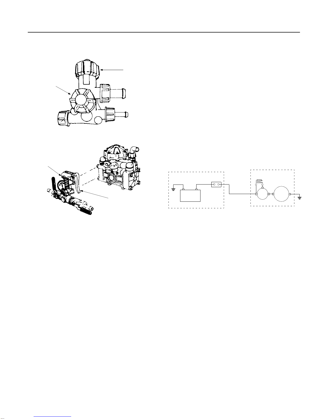
7. Pressure Regulator
Located on the side of the pump opposite the drive
shaft. There are different styles of regulators, but
they all function in the same way. A spring-loaded
plunger rests against a valve seat which forces the
pump flow to the outlets. The springs are opposed
by the hydraulic pressure generated by the pump.
If this pressure exceeds the spring pressure, the
plunger is lifted off of its seat and part or all of the
flow goes to bypass. All of the pressure regulators
have operating levers which in one position,
remove the spring pressure from the plunger and
permit the pump's flow to dump to bypass and in
the other position, apply the spring pressure to the
plunger and force the pump's flow to the outlets.
One valve has a toggle-type operating lever with a
ball which can be hooked in different notches for
adjustment. Another regulator has a knob that
turns about 90° from "OFF" to "ON". Still another
has a hinged part of the plunger shaft work as the
operating lever. All of the regulators also have a
means for adjusting the operating pressure. This is
a threaded knob, a ring or a brass adjustment nut
which when threaded down toward the base of the
pressure regulator, increases the spring pressure.
Normally, the regulator should be set to provide
about 100 psi with both output ball valves closed.
Then the output ball valve to the application device
is opened completely and with bypass or
pressurized jet agitation, the output ball valve to
the agitator line is adjusted to provide the desired