MTD ET 1000 User manual

ET 1000
MTD Products Aktiengesellschaft
Saarbrücken
Germany
FORM NO. 769-00359
C09


ET 1000
1
ENGLISH
TABLE OF CONTENTS
1. Safe operating practices ..................... 1
2. Avvertenze di sicurezza ..................... 1
3. Istruzioni di montaggio .......................... 2
4. Istruzioni d'uso ..................................... 2
5. interventi di manutenzione / riparazione3
6. Diagnostica ........................................... 4
7. Caratteristiche Tecniche ...................... 4
EU Conformity Declaration ........................ 49
1. SAFE OPERATING PRACTICES
USE THE UNIT CORRECTLY
This unit is intended exclusively:
nfor use in accordance with the descrip-
tions and safety instructions specified in
this operating manual,
nfor use in the garden,
nfor mowing lawn edges and small or in-
accessible grassy areas ( e.g. under
bushes).
This unit is not permitted for any other use.
The user is liable for any injury to third par-
ties or damage to their property.
Operate the unit only in the delivered techni-
cal condition as stipulated by the manufac-
turer.
Any unauthorised changes to the unit will
exempt the manufacturer from liability for
any resulting damage.
2. SAFETY WARNINGS
nRead the instructions carefully. Be familiar
with the controls and proper use of the
unit.
nChildren and adolescents (<16 years old)
must not manipulate unit, except for ado-
lescents in training and under the super-
vision of a specialist.
nKeep all bystanders at least 5 m away
from the unit during operation.
nMake sure there are no branches or
stones etc. in the way of the cord or the
cutting blade, before starting up the
appliance.
nUse the unit only in daylight or good
artificial light.
nBe aware of the risk of injury ta the head,
hands and feet.
nWhen working with the unit, always
wear sturdy, rubber-soled footwear and
body protection appropriate to operation
of the unit.
nWhen working with the unit, use the
safety attachments supplied.
nBefore starting, adjust the handle to your
size.
nDo not overreach. Keep proper footing
and balance at all times.
nAll interventions, whether for
maintenance, repair or for changing
cutting head or safety attachments, must
be undertaken with the motor stopped.
nFrequently inspect the condition of the
cutting head, All damaged parts must
immediately be replaced.
nFollow all the required precautions when
undertaking replacement.
nUse only replacement parts
recommended by the manufacturer.
nAll guards must be installed properly
before operating the unit.
nCaution-Danger! Cutting head is still
running.
nKeep unit clean of vegetation and other
materials.
nKeep connecting wires away from the
tools.
nTurn off the unit and pull the main plug
before set-up or cleaning of the unit, and
before testing for tangled or damaged
wires.
nThe connecting wires must be inspected
regularly for signs of damage or age.
nThe unit must not be used if the
connecting wires are not in perfect
condition.
nMaintenance/servicing and cleaning of
MINIMUMWIRE SIZE FOR EXTENSION CORDS
FOR 23OV APPLIANCES USING 0-6 AMPS
Wire size (mm
2
) 1,2 1,6 1,6 2,0
Cord length (m) 7 15 30 45
Attention!
Observe the
following safety
warnings.
Read operator’s
manual.
Wear head, eye
and ear
protection.
Keep
bystanders at
least 15 m away
from unit during
operation.
If the electric
cord is
damaged
remove plug
from socket and
replace it.
Do not operate
unit in rain.
Ignition/Power
Switch On/Start/
Run
Ignition/Power
Switch off or
stop.
et1000_mtd_ing.p65 17/03/03, 10:521

2
ET 1000
the unit or adjustments to cutting height or
work height may only be performed when
the motor is off/still and the main plug is
disconnected.
nCord Sets - Make sure your cord set is in
good condition. When using a cord set,
be sure to use a cord that is heavy
enough to carry the current that your unit
wilI draw. An undersized cord set will
cause a drop in line voltage resulting in
power and overheating.
nThe table (below) shows the correct size
to use depending on the cord length and
nameplate amperage rating. If in doubt,
use the next heavier size Iine gauge. The
smaller the gauge number, the heavier the
cord.
nFor safety reasons, the socket used to
power the unit should be backed up by a
residual current-operated (FI)
circuitbreaker which can be tripped by a
max. current of 30mA.
nA fatal injury could occur if you sever the
mains cable while mowing is taking place.
Slowly step away from the unit. Pull the
plug out of the mains socket.
3. ASSEMBLY INSTRUCTIONS
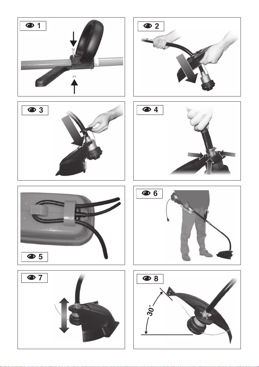
HANDLE
nPush the handle down onto the boom
(NFIG. 1).
nInstall and tighten the bolts and nuts.
STRING GUARD
nPlace the string guard onto the boom
above the clamp assembly (NFIG. 2).
nFit the safety protection onto the bar
above the coupling joint in the direction of
the motor (NFIG. 3)
nSee (NFIG. 4) for putting the safety
protection extension into position.
OPERATING CLICK-LINK® SYSTEM
NOTE: To make installing or removing the
add-on easier, place the unit on the ground
or on a work bench.
Removing the Cutting Attachment or
Add-Ons:
nTurn the knob counterclockwise to loosen
(NFIG. 18).
nPress and hold the release button (N
FIG. 18).
nWhile firmly holding the upper shaft tube,
pull the cutting attachment or add-on
straight out of the Click-Link ®coupler
(NFIG. 19).
Installing the Cutting Attachment or
Add-Ons:
nTurn knob counterclockwise to loosen
(NFIG. 18).
nWhile firmly holding the add-on, push it
straight into the Click-Link ®coupler (N
FIG. 19).
NOTE: Aligning the release button with the
guide recess will help installation (NFIG.
19).
nFOR BASIC TRIMMING OR FOR MOST
ADD-ONS - Locate and lock the release
button into the Primary hole (NFIG. 19).
nTurn the knob clockwise to tighten (N
FIG. 20). Ensure it is tight before operating
the unit.
4. OPERATING INSTRUCTIONS
CONNECTING THE CORD
To prevent disconnection when you
connect the extension cord to the power
cord, use the cord hook (NFIG. 5), or tie
the cords in a knot.
STARTING / STOPPING
nPress control switch to switch on the
appliance, release to switch off.
HOLDING THE TRIMMER
nHold the trimmer as shown FIG. 6
ADJUSTING LINE LENGTH
The trimmer has a bump (cutting) head,
which releases more trimming line without
stopping the motor.
nWhen the cord starts to get a bit short,
knock the cutting head on the bare
ground or on hard ground to make the
appliance work at top speed. Repeat the
process as often as necessary (NFIG.
7).
DECORATIVE TRIMMING
Use a 30-degree angle to remove all
vegetation around trees, posts, fences (N
FIG. 8).
EDGING
When edging, let the tip of the trimming line
do the work (NFIG. 9)
TRIMMING TIPS
(NFIG. 9)
1. The cutting head will be at the correct
angle by holding it parallel to the ground.
2. DO NOT FORCE THE UNIT.
3. Cut to your left for best cutting, and to
throw the clippings away from the
operator.
4. Move the trimmer slowly in and out of
the area being cut, using a forward-
backward or side-to-side motion.
Maintain top speed for best cutting.
5. Trim only when grass and weeds are
dry.
6. The life of your cutting line depends on
your trimming techniques, what is being
cut, and where the cutting is being
done. Some line breakage will occur
from:
et1000_mtd_ing.p65 17/03/03, 10:522

ET 1000
3
ENGLISH
nEntanglement with foreign matter
nNormal line fatigue
nAttempting to cut thick weeds
nForcing the line into walls or
fenceposts
5. MAINTENANCE AND REPAIR INSTRUCTIONS
INSTALLING ANEW TRIMMING LINE
The trimming line may be replaced by two
methods - rewinding the existing reel or
installing a prewound reel.
REWINDING THE EXISTING REEL
To rewind the existing reel you must:
nCheck for the correct line size.
nRemove the inner reel and spring.
nWind the reel with the new line.
nReinstall the existing reel and spring.
THE CORRECT LINE TO USE
Use a dual line reel with Ø2,00 mm.
REMOVING THE EXISTING REEL
nUnscrew the Bump Knob
counterclockwise (NFIG. 10).
nRemove the inner reel (NFIG. 11).
nUse a clean cloth to clean the inside of
the outer spool (NFIG. 12).
nCheck the indexing teeth on the reel and
spool for wear (NFIG. 13). If
necessary, replace the reel and spool.
WINDING THE EXISTING REEL
nInsert the ends of new trimming line into
the inner reel holes (NFIG. 14).
nLoop the line into two equal lengths
before inserting it into the holes.
nWind the line, in even and tight layers
(NFIG. 15), onto the reel, and in the
direction indicated.
nPush the ends of the line into the
slots(NFIG. 16).
REINSTALLING THE REEL
nInsert the ends of the line through the
eyelets in the outer spool (NFIG. 17).
nGrasp the ends and pull firmly to release
the line from the slots in the spool.
nInstall the Bump Knob clockwise (NFIG.
10).
Line installation is now complete.
INSTALLING APREWOUND REEL
nUse the same instructions as the existing
reel:
nThe Correct Line to Use;
nRemoving the Existing Reel;
nReinstalling the Reel.
CLEANING / STORAGE
nDo not block the air vents.
nDo not use strong detergents on the
plastic housing or handle.
nMoisture can cause a shock hazard.
Wipe off moisture with a soft cloth.
nClean the unit thoroughly before storing.
Hang the unit by the handle loop and
store it in a dry, well-ventilated area, out
of the reach of children.
et1000_mtd_ing.p65 17/03/03, 10:523

4
ET 1000
PROBLEM
nMotor will not start
nCutting head will not turn
when throttle is squeezed
nCutting head will not
advance line
6. TROUBLESHOOTING
CAUSE
1. Motor stops / will not
start
2. Cutting head bound with
grass or debris
1. Flex shaft broken
2. Flex shaft not engaged
1. Cutting head out of line
2. Inner reel bound up
3. Cutting head dirty
4. Indexing teeth worn or
burred
5. Line welded
6. Line twisted when re-
filled
7. Nut enough line is
exposed
ACTION
1. Check curd to see if it is
plugged into an electrical
outlet
2. Stop motor and clean
cutting head
1. Contact service dealer
2. Contact service dealer
1. Refill with new cutting
line
2. Replace inner reel
3. Clean inner reel and
outer spool
4. Replace inner reel and
outer spool
5. Disassemble, remove
the welded section and
rewind the line
6. Disassemble and rewind
reel
7. Push the Bump Knob
and pull out 102 mm of
line until the line is
outside of the cutting
head
7. SPECIFICATIONS
MOTOR
Motor ................................................................................................................................... Electric
Ignition Switch ......................................................................................................... Control switch
Drive shaft ........................................................................................................................... 6,2 mm
Cutting head .......................................................................................... "Bump Head" reel feeding
Vibration Level ................................................................................................................. 2,15 m/s2
Sound pressure level (no load) .................................................................... LPAm = 75,75 dB (A)
Measured sound power level (no load) .......................................................... LWA = 95,36dB (A)
Guaranteed sound power level (no load) ........................................................... LWA = 96 dB (A)
Cutting path diameter .......................................................................................................... 370 mm
Operating weight .................................................................................................................. 5,5 Kg
Trimming line diameter .......................................................................................................... 2,0 mm
All information, illustrations and specifications in this manual are based on the latest product
information available at the time of printing, We reserve the right to make changes at any time
without notice.
et1000_mtd_ing.p65 17/03/03, 10:524
Operating RPM ...................................................................................................... 7000 - 8000 /min

ET 1000
5
FRANÇAIS
SOMMAIRE
1. Pour votre securite ............................... 5
2. Consignes de sécurité......................... 5
3. Instructions de montage ....................... 6
4. Instructions d’utilisation ........................ 6
5. Instructions d’entretien / réparation ..... 7
6. Dépannage ........................................... 8
7. Spècifications ....................................... 8
Déclaration de ConformitéCE ................... 49
1. POUR VOTRE SECURITE
UTILISATION CONFORME DE L'APPAREIL
Cet appareil est exclusivement destinéà
servir:
nconformément aux descriptions et consi-
gnes de sécuritéfournies dans la pré-
sente notice d'instructions,
ndans le jardin domestique et le jardin
d'agrément,
npour tondre les bordures gazonnées et
les surfaces herbeuses restreintes ou
difficiles d'accès (par ex. sous les
buissons).
Toute utilisation sortant de ce cadre sera
réputée non conforme.
Tout dommage envers un tiers et ses biens
est àla charge de l'utilisateur.
N'utilisez l'appareil que dans l'état technique
oùvous l'avez achetéet tel que prescrit par
le fabricant.
Toute modification volontaire de l'appareil
exclut toute responsabilitédu fabricant en-
vers les dommages qui pourraient
en résulter.
2. CONSIGNES DE SÉCURITÉ
nLisez attentivement les instructions.
Familiariser-vous avec les commandes et
Ie maniement de l’appareil.
nLes enfants et adolescents (<16 années)
ne doivent pas manipuler les appareils, à
l’exception des adolescents en formation
sous la surveillance d’un spécialiste.
nLes personnes présentés doivent se tenir
éloignées de 15 m minimum de l’appareil
en fonctionnement.
nAvant de redémarrer l'appareil, vérifiez
que le fil ou la lame de coupe ne touche ni
branches, ni pierres, etc…
nUtilisez l’appareil uniquement de jour ou
avec un bon éclairage artificiel.
nFaites attention aux risques de blessure à
la tête aux mains et aux pieds.
nLorsque vous utilisez l’appareil, vous
devez toujours porter des chaussures
solides avec des semelles anti-
dérapantes et un équipement de
protection corporelle approprié.
nLorsque vous travaillez avec l’appareil,
utiliser les dispositifs de protection
fournis.
nAvant de commencer àtravailler, réglez la
poignée àvotre taille.
nNe présumez pas de vos forces. Veillez à
prendre des appuis stables àtous
moments.
nLes interventions d’entretien et de
réparation, ainsi que le changement de la
tête de coupe et l’enlèvement dss
dispositifs de protection ne doivent être
effectués que lorsque le moteur est à
l’arrêt.
nContrôlez fréquemment l’état de la tête de
coupe. Toute pièce endom-magée doit
être immédiatement remplacée. Suivez
toutes les précautions nécessaires lors
de ce remplacement.
nN’utiliser que les pièces détachées
recommandées par Ie fabricant.
nVous devez installer correctement toutes
les protections avant d’utiliser I’appareil.
nAttention! Danger! La tête de coupe
continue àtourner!
nVeillez àce que l’appareil ne soit pas
enco mbréde végétation ou autres
matériaux.
nGardez toujours le cordon d’alimentation
et les rallonges àdistance des outils de
SECTION MINIMUM DES PROLONGATEURS POUR
DES APPAREILS DE 230VOLTS UTILISANT DE 0 A
6 AMPERES
Section (mm
2
) 1,2 1,6 1,6 2,0
Longueur (m) 7 15 30 45
Attention!
Observez les
consignes de
sécurité
suivantes.
Lisez le manuel
d’utilisation.
Portez des
lunettes et des
protège-oreilles
et tête.
Les personnes
présentes
doivent se tenir
éloignées de 15
m minimum de
l’appareil en
fonctionnement.
Si le câble
électrique est
abîméenlevez
la fiche et
remplacez-le.
N’utilisez pas
l’appareil sous
la pluie.
Interrupteur
marche. On/
Start/Run.
Interrupteur
arrêt. off ou
stop.
et1000_mtd_fra.p65 17/03/03, 10:525

6
ET 1000
coupe.
nÉteignez l’appareil et débranchez la prise
principal0 avant tout ajustage ou
nettoyage. •Procédez de même
pour tester les cordons enchevêtrés ou
abîmés.
nLes cordons doivent être vérifiés
régulièrement afin de détecter tout
dommage ou usure.
nL’appareil ne doit être utiliséque si les
cordons sont en parfaite condition.
nNe procéder àl’entretien et au nettoyage
de l’appareil ou au réglage de la position
de coupe que lorsque le moteur est arrêté
et que le cordon d’alimentation est
débranché.
nProlongateurs: Assurez-vous qu’ils sont
en bon état et d’un calibre suffisant pour
transporter le courant nécessaire à
l’appareil. Un cordon de taille insuffisante
provoquerait une baisse de tension et
une surchauffe. Le tableau ci-dessous
indique la dimension correcte àutiliser en
fonction de la longueur du cordon et du
nombre d’ampères. En cas de doute,
utilisez un cordon d’un calibre supérieur.
Plus le chiffre correspondant au calibrage
est petit, plus le cordon est résistant.
nPour des raisons de sécurité, l'appareil
doit être branchéàune prise électrique
protégée par un interrupteur différentiel
avec un courant maximum de 30 mA.
nEn cas de coupure accidentelle du câble
électrique d'alimentation pendant l'utilisa-
tion de l'appareil, débrancher immédiate-
ment la fiche de la prise électrique.
3. INSTRUCTIONS DE MONTAGE
POIGNÉE
nFaites glisser la poignée le long du man-
che (NFIG. 1).
nMettez en place l’écrou, le boulon, puis
serrez.
CAPOT DE PROTECTION
nMontez la protection sur la tige au-dessus
du raccord d'accouplement en l'orientant
vers le moteur (NFIG. 2).
nPlacez la rallonge de protection de la
façon illustrée sur la (NFIG. 3).
nMettez les vis en place àl’aide d’un
tournevis Phillips (NFIG. 4).
FONCTIONNEMENT DU CLICK-LINK
Retrait de l'accessoire de coupe ou
autres:
nDévissez le bouton vers la gauche (N
FIG. 18).
nAppuyez sur le bouton de déclenchement
et maintenez-le enfoncé(NFIG. 18).
nTenez fermement le tube de l'arbre supé-
rieur et retirez l'accessoire de coupe ou
autre du coupleur Click-Link (NFIG. 19).
Installation de l'accessoire de coupe
ou autre:
nDévissez le bouton vers la gauche (N
FIG. 18).
nTenez fermement l'accessoire et enfon-
cez-le tout droit dans le coupleur Click-
Link MD (NFIG. 19)
NOTE: Alignez le bouton de déclenchement
avec le renfoncement-guide pour faciliter
l'installation (NFIG. 19).
nPOUR LE DÉSHERBAGE DE BASE OU LA
PLUPART DESACCESSOIRES - Repérez
et verrouillez le bouton de déclenchement
dans le trou principal (NFIG. 19).
nSerrez le bouton en le tournant àdroite
(NFIG. 20). Vérifiez qu’il est bien serré
avant de faire fonctionner l’appareil.
4. INSTRUCTIONS D’UTILISATION
CONNEXION DU PROLONGATEUR
Afin d’éviter toute déconnexion intem-
pestive lorsque vous connectez le
prolongateur au cordon d’alimentation,
utilisez le fixe-cordon (NFIG. 5). Vous
pouvez également nouer le prolongateur et
le cordon.
DÉMARRAGE / ARRÊT
nPour démarrer l'appareil appuyez sur
l'interrupteur de commande et lâchez-le
pour l'arrêter.
MANIEMENT
nTenez le coupe-bordures comme indiqué
FIG. 6
RÉGLAGE DE LA LONGUEUR DU FIL DE COUPE
Ce coupe-bordure possède un système de
coupe àfil, permettant de dérouler le fil de
coupe sans arrêter le moteur.
nLorsque le câble commence àêtre court,
frappez la tête de coupe directement sur
le sol ou sur un terrain dur en faisant
fonctionner l'appareil àgrande vitesse
(NFIG. 7).
COUPE DÉCORATIVE
Inclinez l’appareil selon un angle de 30°pour
retirer toute végétation autour des arbres,
des poteaux, des haies etc. (NFIG. 8).
BORDURES
Lorsque vous coupez des bordures, lais-
sez l’extrémitédu fil effectuer la coupe.
COUPE DES BORDURES
(NFIG. 9)
1. La tête de coupe se trouvera àun angle
correct en étant parallèle au sol.
2. NE FORCEZ PAS L’APPAREIL.
3. Pour effectuer une meilleure coupe et
évacuer les débris d’herbe loin de vous,
travaillez sur votre gauche.
et1000_mtd_fra.p65 17/03/03, 10:526

ET 1000
7
FRANÇAIS
4. Déplacez le coupe-bordures lentement
àl’intérieur et àl’extérieur de la zone de
coupe, par un mouvement d’avant en
arrière et de gauche àdroite.
Conservez une vitesse élevée pour une
meilleure coupe.
5. Coupez uniquement lorsque le gazon et
les herbes sont secs.
6. La durée de vie de votre fil dépend de
vos techniques de coupe, de ce que
vous coupez, et des endroits oùvous
effectuez ces coupes. Des ruptures de
fil peuvent être causées par:
ndes objets s’accrochant au fil;
nune usure normale du fil;
nune tentative de couper des herbes
épaisses et robustes;
nun choc contre des murs ou des
barrières.
5. INSTRUCTIONS D’ENTRETIEN / RÉPARATION
INSTALLATION D’UN NOUVEAU FIL DE COUPE
Vous pouvez remplacer le fil de coupe de
deux manières différentes : en enroulant un
nouveau fil sur la bobine existante ou en
installant une nouvelle bobine de fil.
UTILISATION DE LA BOBINE EXISTANTE
Pour utiliser la bobine réceptrice existante,
vous devez:
nVérifier le diamètre du fil àutiliser.
nEnlever la bobine réceptrice et le ressort.
nEnrouler le nouveau fil de coupe sur la
bobine réceptrice.
nRéinstaller la bobine réceptrice et le
ressort.
FIL DE COUPE ÀUTILISER
Utilisez une bobine réceptrice àdeux fils
avec un fil de coupe de Ø2,00 mm.
DÉMONTAGE DE LA BOBINE EXISTANTE
nDévissez le bouton de serrage du fil dans
le sens inverse des aiguilles d’une montre
(NFIG. 10).
nDémontez la bobine réceptrice (NFIG.
11).
nA l’aide d’un chiffon propre, nettoyez
l’intérieur de la bobine débitrice (NFIG.
12).
nVérifiez le degréd’usure des dents (N
FIG. 13). Si nécessaire, remplacez les bo-
bines réceptrice et débitrice.
ENROULAGE DU FIL
nInsérez les extrémités du nouveau fil de
coupe dans les trous de la bobine
réceptrice (NFIG. 14).
nFormez une boucle de façon àobtenir
deux longueurs égales avant d’insérer le
fil dans les trous.
nEnroulez le fil autour de la bobine en
couches régulières et serrées (NFIG.
15), dans le sens indiqué.
nPlacez les extrémités du fil dans les en-
coches (NFIG. 16).
RÉINSTALLATION DE LA BOBINE
nInsérez les extrémités du fil dans les
oeillets de la bobine débitrice (NFIG.
17).
nAttrapez les extrémités et tirez ferme-
ment, afin de libérer le fil des encoches
de la bobine réceptrice.
nSerrez le bouton de serrage dans le sens
des aiguilles d’une montre (NFIG. 10).
L’installation du fil est maintenant terminée.
INSTALLATION D’UNE NOUVELLE BOBINE
nProcédez comme pour la bobine
réceptrice existante:
nChoix du fil de coupe àutiliser;
nDémontage de la bobine réceptrice
existante;
nRéinstallation de la bobine réceptrice.
NETTOYAGE / STOCKAGE
nN’obstruez pas les filtres àair.
nN’utilisez pas de détergeants puissants
sur les revêtements en plastique ni sur la
poignée.
nL’humiditéentraîne des risques de courts-
circuits. Essuyez donc bien la machine
avec un chiffon doux.
nNettoyez soigneusement l’appareil avant
de l’entreposer. Accrochez-le par la
poignée dans un endroit sec et aéré, hors
de portée des enfants.
et1000_mtd_fra.p65 17/03/03, 10:527

8
ET 1000
PROBLÈME
nLe moteur ne démarre pas
nLa tête de coupe ne
tourne pas lorsque le bou-
ton d’accélération est ac-
tionné
nLa tête de coupe ne fait
pas avancer le fil
6. DÉPANNAGE
CAUSE
1. Le moteur s’arrête/ne
démarre pas
2. Tête de coupe encom-
brée d’herbe et de dé-
bris
1. Arbre flexible cassé
2. Arbre flexible mal en-
gagé
1. Plus de fil dans la tête
de coupe
2. Bobine réceptrice
bloquée
3. Tête de coupe
encrassée
4. Dents usées et
5. Fil noué
6. Fil tordu lors de son
rembobinage
7. Pas assez de fil à
ACTION
1. Vérifiez si le cordon de
raccordement est
branchésur une prise
électrique
2. Arrêtez le moteur et
nettoyez la tête de
coupe
1. Contactez votre
distributeur agréé
2. Contactez votre
distributeur agréé
1. Réinstallez du fil
2. Remplacez la bobine ré-
ceptrice
3. Nettoyez la bobine
réceptrice et la bobine
débitrice
4. Remplacez la bobine
réceptrice ébarbées et
la bobine débitrice
5. Demontez la tête, ôtez la
partie nouée et
rembobinez le fil
6. Demontez et rembobinez
7. Appuyez sur le bouton
de l'extérieur déblocage
du fil et tirez 102 mm de
fil, jusqu'àce que ce
dernier soit hors de la
tête de coupe
7. SPÈCIFICATIONS
MOTEUR
Moteur ............................................................................................................................. Electrique
Démarreur .................................................................................................... Bouton d’accélération
Arbre d’entraînement ........................................................................................................... 6,2 mm
Tête de coupe ..................................................................... Avance du fil de coupe "Bump Head"
Niveau de vibration .......................................................................................................... 2,15 m/s2
Niveau de pression du son(sans charge) ................................................... LPAm = 75,75 dB (A)
Niveau de puissance du son mesuré(sans charge) ..................................... LWA = 95,36dB (A)
Niveau de puissance du son àgarantie (sans charge) ..................................... LWA = 96 dB (A)
Diamètre trajectoire de coupe ............................................................................................ 370 mm
Poids ...................................................................................................................................... 5,5 Kg
Diamètre du fil de coupe ...................................................................................................... 2,0 mm
Toutes les informations, illustrations et spécifications de ce manuel sont basées sur les der-
nières informations disponibles au moment oùnous les imprimons. Nous nous réservons le
droit d’apporter des modifications àtout moment, sans notification préalable.
et1000_mtd_fra.p65 17/03/03, 10:528
Régime nominal .....................................................................................................7000 - 8000 /min

ET 1000
9
DEUTSCH
INHALTSVERZEICHNIS
1. Zu ihrer sicherheit ................................ 9
2. Gefahrenhinweise ............................... 9
3. Einbauanweisungen ........................... 10
4. Benutzungsanweisungen .................. 10
5. Wartungs-und reparaturanweisungen11
6. Pannenhilfe ......................................... 12
7. Spezifikationen ................................... 12
EG Konformitätserklärung......................... 49
1. ZUIHRER SICHERHEIT
DAS GERÄTRICHTIG VERWENDEN
Dieses Gerät ist ausschließlich bestimmt:
nzur Verwendung entsprechend den in
dieser Bedienungsanleitung gegebenen
Beschreibungen und Sicherheitshin-
weisen,
nzur Verwendung im Bereich des Haus-
und Freizeitgartens,
nzum Mähen von Rasenkanten und kleinen
oder schwer zugänglichen Grasflächen
(z. B. unter Büschen)
Dieses Gerät ist für einen darüber hinaus-
gehenden Gebrauch nicht zugelassen.
Der Benutzer haftet für alle Schäden an
Dritten und deren Eigentum.
Betreiben Sie das Gerät nur in dem vom
Hersteller vorgeschriebenen und ausgelie-
ferten technischen Zustand.
Eigenmächtige Veränderungen an dem Ge-
rät schließen eine Haftung des Herstellers
für daraus resultierende Schäden aus.
2. GEFAHRENHINWEISE
nLesen Sie diese Anweisungen sorgfältig
durch. Machen Sie sich mit der Bedienung
und der Handhabung des Gerätes ver-
traut.
nKinder und Jugendliche(unter 16J.) dür-
fen Geräte mit metallischen Arbeits-
werkzeugen nicht handhaben, ausge-
nommen sind Jugendliche in der Ausbil-
dung unter Aufsicht eines Fachkundigen.
nEs dürfen sich keine Personen in weniger
als 15 m Entfernung von dem Gerät auf-
halten, während es in Betrieb ist.
nVor dem Starten mußdarauf geachtet
werden, daßder Schneidkopf keine Be-
rührung mit Gegenstanden, z-B. Äste,
Steine usw., hat.
nDas Gerät darf nur tagsüber bzw. bei gu-
ter künstlicher Beleuchtung eingesetzt
werden.
nSeien Sie sich der Verletzungsgefahr von
Kopf, Händen und Füßen bewußt.
nBeim Arbeiten mit dem Gerät mußfestes
Schuhwerk mit griffiger Sohle und sach-
gemäße Körperschutzausrüstung ent-
sprechend dem jeweiligen Verwendungs-
zweck getragen werden.
nArbeiten Sie nie ohne die vorgesehenen
Schutzvorrichtungen mit dem Gerät.
nDer Griff mußvor Arbeitsbeginn entspre-
chend der Körpergrösse eingestellt wer-
den.
nÜberschätzen Sie sich nicht, Beim Arbei-
ten ist auf einen sicheren Stand zu ach-
ten.
nWartungs- und Reinigungsarbeiten sowie
das Auswechseln der Abeitswerkzeuge
und das Abnehmen der Schutzein-
richtungen dürfen nur bei stiIlgesetztem
Motor vorgenommen werden.
nDer Schneidekopf ist in regelmäßigen kur-
zen Abständen auf Beschädigung zu prü-
fen und gegebenenfalls sofort auszutau-
schen. Beim Auswechseln sind die erfor-
derlichen Vorsichtsmaßnahmen zu tref-
fen.
nEs dürfen nur die vom Hersteller empfoh-
lenen Ersatzteile verwendet werden.
nAlle Schutzeinrichtungen müssen
ordnungsgem angebracht sein, bevor Sie
mit dem Gerät zu arbeiten beginnen.
nAchtung Gefahr! Schneidwerkzeug läuft
nach.
nAchten Sie darauf, daßkeine Pflanzen
oder sonstige Gegenstände im Gerät ver-
fangen sind.
MIN. LEITUNGSQUERSCHNIIT DER
VERLÄNGERUNGSKABEL FÜR DIESES GERÄT
Querschnitt
1,2 1,6 1,6 2,0
Kabellänge (m) 7 15 30 45
Achtung! Beachten
Sie folgende
Sicherheitshinweise.
Lesen Sie die
Bedienanleitung.
Tragen Sie
Sicherheitsbrille und
Gehörschutz.
Es dürfen sich keine
Personen in weniger
als 15 m Entfernung
von dem Gerät
aufhalten, während
es in Betrieb ist.
Bei Beschädigung
des Elektrokabels
den Stecker aus der
Steckdose nehmen
und durch ein neues
ersetzen.
Verwenden Sie das
Gerät nicht im
Regen.
Einschalter. On/
Start/Run.
Ausschalter. Off
oder Stop.
et1000_mtd_ted.p65 17/03/03, 11:279

10
ET 1000
nHalten Sie Strom- und Verlängerungskabel
immer von den Schneidwerkzeugen ent-
fernt.
Schalten Sie das Gerät ab und ziehen Sie
den Stecker aus der Steckdose, bevor Sie
das Gerät einstellen oder reinigen und be-
vor Sie es auf verwickelte bzw. beschä-
digte Kabel prüfen.
Die Kabel müssen regelmäßig geprüft wer-
den, um Beschädigung und Verschleißmit
Sicherheit festzustellen.
Das Gerät darf nur mit Kabeln in einwand-
freiem Zustand benutzt werden.
Wartungs-und Reinigungsarbeiten am Gerät
und das Verstellen der Schnitt-bzw.
Arbeitshöhe dürfen nur bei stillgesetztem
Motor und gezogenem Netzstecker vor-
genommen werden.
Gehen Sie sicher, dass Ihre Kabel in gutem
Zustand sind, und dass Sie ein Kabel ver-
wenden, das stark genug ist für den
Strom, den Ihr Gerät abnehmen wird.
Ein zu kleines Kabel würde einen Span-
nungsabfall verursachen, der wiederum
Überhitzung und Spannungsabfall hervor-
rufen würde.Die Tabelle zeigt die zu ver-
wendende korrekte Grösse, welche von
der Länge des Kabels und der auf dem
Namensschild angegebenen Ampèrezahl
abhängt.Im Zweifelsfall benutzen Sie die
nächstgrössere Leitungsstärke.Je kleiner
die Messzahl, desto stärker das Kabel.
nVerwenden Sie an Ihrer Netzsteckdose
einen Personenschutzschalter (=Fehler-
stromschutzschalter mit höchstens 30mA
Auslösestrom).
nSollten Sie beim Mähen das Kabel durch-
trennen, besteht Lebens- oder Verlet-
zungsgefahr. Entfernen Sie Sich langsam
in kleinen Schritten vom Gerät. Ziehen Sie
den Stecker aus der Steckdose.
3. EINBAUANWEISUNGEN
HANDGRIFF
nLassen Sie den Handgriff den Schaft ent-
lang gleiten (NABB. 1).
nPlazieren Sie die Schraube und die mutter
und ziehen Sie sie fest.
SCHUTZKAPPE
nDen Schutz auf die Stange oberhalb des
Verbindungsstückes montieren sodaßer
Richtung Motor zeigt (NABB. 2).
nDie Schutzverlängerung wie in (NABB.
3) positionieren.
nMontieren sie die Schrauben mit en
Schraubendreher (NABB. 4).
BENUTZEN DES CLICK-LINK ®SYSTEMS
Entfernen von Schneidaufsatz oder an-
deren Aufsätzen:
nUms drehen (NABB. 18).
nDen Auslöseknopf drücken und halten
(NABB. 18).
nDas obere Achsengehäuse gut festhalten
und den Schneidaufsatz oder anderen
Aufsatz gerade aus der Click-Link ®
Kupplung ziehen (NABB. 19).
Installieren des Schneidaufsatzes
oder anderer Aufsätze:
nUm den Aufsatz zu lösen, den Schraub-
griff nach links drehen (NABB. 18).
nDen Aufsatz gut festhalten und gerade in
die Click-Link ®Kupplung schieben (N
ABB. 19).
HINWEIS: Ausrichten des Auslöseknopfs
mit der Führungsrille macht den Einbau
leichter (NABB. 19).
nZUM EINFACHEN TRIMMEN UND FÜR DIE
MEISTEN AUFSÄTZE - Das Hauptloch fin-
den und den Auslöseknopf einrasten las-
sen (NABB. 19).
nZur Befestigung den Knopf nach rechts
drehen (NABB. 20). Versichern Sie sich
vor Betrieb, daßder Drehgriff fest sitzt.
4. BENUTZUNGSANWEISUNGEN
ANSCHLUSSDES VERLÄNGERUNGSKABELS
Verwenden Sie immer den
Kabelhalter,wenn Sie das Verlängerungs-
kabel anschließen,um eine ungewollte Tren-
nung sicher zu verhindern (NABB. 5).Sie
können auch eine Knotenverbindung zwi-
schen Verlängerungsschnur und
Versorgungsschnur herstellen.
EIN-/AUSSCHALTEN
nZum Einschalten den Start-Schalter
drücken,und zum Abschalten diesen wie-
der kurz betätigen.
HANDHABUNG
nHalten Sie den Rasenrandschneider wie
abgebildet (NABB. 6).
LÄNGENEINSTELLUNG DES SCHNEIDFADENS
Dieser Rasenrandschneider ist mit einem
Bump-Head-System ausgestattet,durch das
der Schneidfaden abgewickelt werden
kann, ohne den Motor abzustellen.
nWenn der Schneidfaden kurz zu werden
droht,den Scherkopf auf nackten Erdbo-
den oder harten Boden schlagen und da-
bei das Gerät bei großer Geschwindigkeit
laufen lassen (NABB. 7).
DEKORATIVER SCHNITT
Neigen Sie den Rasenrandschneider in ei-
nem 30°-Winkel,um die Vegetation um die
Bäume Pfosten,Schranken usw. herum zu
entfernen (NABB. 8).
RASENRAND
Lassen Sie das Ende des Schneidedrahtes
am Rasenrand seine Schnittfunktion aus-
üben.
et1000_mtd_ted.p65 17/03/03, 11:2710

ET 1000
11
DEUTSCH
RASENRANDSCHN ITT
(NABB. 9)
1. Der Schneidekopf mußparallel zum Bo-
den gehalten werden.
2. ÜBERBEANSPRUCHEN SIE DAS GERÄT
NICHT.
3. Arbeiten Sie nach links,um optimale
Schnittergebnisse zu erzielen und das
Schnittgut sowie Steine u.ä.vom Bedie-
ner weg zu schleudern.
4. Führen Sie den Rasenrandschneider
langsam in den Schnittbereich hinein
und wieder heraus,indem Sie Vorwärts-
/Rückwärtsbewegungen oder seitliche
Bewegungen ausführen. Behalten Sie
für beste Schnittergebnisse die hohe
Geschwindigkeit aufrecht.
5. Schneiden Sie nur Rasen und Gras in
trockenem Zustand.
6. Die Lebensdauer Ihres Schneidfadens
ist von Ihrer Schnittechnik,dem Schnitt-
gut und den Stellen, an denen Sie das
Gerät einsetzen, abhängig. Fadenbruch
auf folgenden Ursachen beruhen:
nes haben sich Steine, Äste o.ä.. am
Faden verfangen;
nder normale Verschleißdes Fadens;
nSie haben versucht,zu dicke Stengel
zu schneiden;
ndas Gerät ist gegen eine Mauer oder
Schranke geprallt.
5. WARTUNGS-UND REPARATURANWEISUNGEN
EINBAU EINES NEUEN SCHNEIDFADENS
Sie können den Schneidfaden auf zwei Ar-
ten ersetzen:indem Sie einen neuen Faden
auf die vorhandene Rolle wickeln oder in-
dem Sie eine neue Fadenrolle einbauen.
WEITERVERWENDUNG DER VORHANDENEN ROLLE
Gehen Sie folgendermaßen vor:
nVergewissern Sie sich hinsichtlich der
einzusetzenden Fadenart.
nNehmen Sie die Aufwickelrolle und die Fe-
der heraus.
nWickeln Sie den neuen Schneidfaden auf
die Rolle auf.
nSetzen Sie Aufwickelrolle und Feder wie-
der ein.
ZUVERWENDENDER SCHNEIDFADEN
Nehmen Sie eine Doppelfaden-Aufwickelrolle
mit einem Schneidfaden von Ø2,00 mm.
AUSBAU DER VORHANDENEN ROLLE
nDie Schraube des Festziehknopfes im
Gegenuhrzeigersinn los (NABB. 10).
nBauen Sie die Aufwickelrolle aus (N
ABB. 11).
nReinigen Sie die Aufwickelrolle mit einem
sauberen Lappen (NABB. 12).
nPrüfen Sie den Verschleißder Zähne
(NABB. 13).Falls erforderlich,wechseln
Sie die Auf-und Abwickelrollen aus.
AUFWICKELN DES FADENS
nFühren Sie die Enden des neuen Schneid-
fadens in die öcher der Aufwickelrolle ein
(NABB. 14).
nBilden Sie einen Schleife,um zwei gleiche
Fadenlängen zu erhalten, bevor Sie den
Faden in die öcher der Spule einführen.
nWickeln Sie den Faden gleichmäßig und
eng (NABB. 15) in der angegebenen
Richtung auf.
nFühren Sie die Fadenenden in die Schlitze
ein (NABB. 16).
WIEDEREINBAU DER ROLLE
nFühren Sie die Fadenenden in die Ösen
der Abwickelrolle ein (NABB. 17).
nZiehen Sie kräftig an den Fadenenden um
den Faden aus der Aussparung der Auf-
wickelrolle hervorzuziehen.
nSchrauben Sie den Festziehknopf in
Uhrzeigerrichtung wieder fest (NABB.
10).
Der Fadeneinbau ist hiermit abgeschlossen.
EINBAU EINER NEUEN ROLLE
nGehen Sie wie bei der Wiederwer-
wendung der vorhandenen Aufwickel-
rolle vor:
nWahl des zu verwendenden Schneid-
fadens;
nAusbau der vor handenen Aufwickel-
rolle;
nWiedereinbau der Aufwickelrolle.
REINIGUNG /AUFBEWAHRUNG
nVerstopfen Sie die Luftfitter nicht.
nVerwenden Sie keine scharfen Reini-
gungsmittel für die Plastikteile und den
Griff.
nFeuchtigkeit birgt Kurzschlußrisiken. Wi-
schen Sie das Gerät gründlich mit einem
weichen Lappen ab.
nReinigen Sie den Rasenrandschneider
sorgfältig,bevor Sie ihn wegräumen. Set-
zen Sie ihn immer in seine Wandhalterung
ein,die sich in einem trockenen und gut
belüfteten Raum außerhalb der Reich-
weite von Kindern befinden muß.
et1000_mtd_ted.p65 17/03/03, 11:2711

12
ET 1000
PROBLEM
nDer Motor springt nicht an
nDer Schneidekopf dreht
sich nicht,wenn der Gast-
aster betätigt wird
nDer Schneidfaden wickelt
sich nicht ab
6. PANNENHILFE
URSACHE
1. Motor bleibt stehen /läuft
nicht an
2. Schneidekopf durch
Gras oder sonstige Ge-
genstände blockiert
1. Flexible Welle gebro-
chen
2. Flexible Welle falsch ein-
gefühlt
1. Es ist kein Faden mehr
vorhanden
2. Aufwickelrolle sitzt fest
3. Schneidekopf ver-
schmutzt
4. Zähne abgenutzt und
schartig
5. Fäden verwickelt schar-
tig
6. Faden ist beim Einsetzen
verbogen worden
7. Nicht genügend Faden
nach außen gezogen
EINGRIFF
1. Prüfen Sie,ob das An-
schlußkabel in einer
Steckdose steckt
2. Motor abschalten und
Schneidekopf reinigen
1. Sprechen Sie Ihren
Vertragshändler an
2. Sprechen Sie Ihren
Vertragshändler an
1. Neuen Faden einsetzen
2. Die Aufwickelrolle aus-
wechseln
3. Auf-und Abwickelrolle
reinigen
4. Auf-und Abwickelrolle
auswechseln
5. Kopf ausbauen,den ver-
wickelten Teil heraus-
nehmen und den Faden
neu aufwickeln
6. Ausbauen und neu auf-
wickeln
7. Fadenlöseknopf betäti-
gen und 102 mm Faden
berausziehen, bis er
aus dem Schneidekopf
hervorsteht
7. SPEZIFIKATIONEN
MOTOR
Betriebsart .......................................................................................................................Elektrisch
Einschalter ................................................................................................................ Start-Schalter
Antriebswelle....................................................................................................................... 6,2 mm
Schneidekopf .................................................. Stoßweiser Fadenvorschub Bump-Head-System
Vibrationen ....................................................................................................................... 2,15 m/s2
Der gemessene A-Shalldruckpegel (im Leerlauf) ........................................ LPAm = 75,75 dB (A)
Schalleistungsstufe gemessen (im Leerlauf) ................................................. LWA = 95,36dB (A)
Schalleistungs - Stufe Gewährleistet (im Leerlauf) ............................................ LWA = 96 dB (A)
Schnittkreisdurchmesser.................................................................................................... 370 mm
Gewicht ................................................................................................................................ 5,5 Kg
Schneidfaden Durchmesser ............................................................................................... 2,0 mm
Alle Informationen, Illustrationen und Spezifikationen des vorliegenden Handbuchs basieren
auf den Daten, die uns bei der Drucklegung zur Verfügung standen. Wir behalten uns das
Recht vor, jederzeit ohne vorherige Bekanntgabe Änderungen vorzunehmen.
et1000_mtd_ted.p65 17/03/03, 11:2712
Nenndrehzahl ........................................................................................................7000 - 8000 /min

ET 1000
13
ITALIANO
SOMMARIO
1. Per la vostra sicurezza ...................... 13
2. Avvertenze di sicurezza ................... 13
3. Istruzioni di montaggio ........................ 14
4. Istruzioni d'uso ................................... 14
5. Interventi di manutenzione /
riparazione .......................................... 15
6. Diagnostica ......................................... 16
7. Caratteristiche tecniche ..................... 16
Dichiarazione di ConformitàCE ................ 49
1. PER LA VOSTRA SICUREZZA
USO CORRETTO DELL'APPARECCHIO
Questo apparecchio èdestinato esclusiva-
mente:
nall'impiego secondo le descrizioni e le
istruzioni di sicurezza fornite in queste
istruzioni per l'uso,
nper l'uso nel giardinaggio domestico e ri-
creativo,
nper rasare i bordi di prati e superfici erbo-
se piccole o difficilmente accessibili (per
es. sotto le siepi),
Non èautorizzato un uso diverso di questo
apparecchio.
L'utilizzatore risponde dei danni arrecati ai
terzi ed alle loro proprietà.
Usate l'apparecchio solo nello stato tecnico
prescritto e fornito dal produttore.
Le modifiche non autorizzate all'apparec-
chio escludono una responsabilitàdel pro-
duttore per i danni da ciòderivanti.
2. AVVERTENZE DI SICUREZZA
nLeggere attentamente le istruzioni.
Familiarizzarsi con l'uso dei comandi e
con l'utilizzo dell'apparecchio.
nI bambini ed in genere i minorenni (< 16
anni) non devono maneggiare gli utensili,
a meno che non sia per ragioni pedagogi-
che e sotto il controllo di uno specialista.
nDurante il funzionamento dell'apparecchio
nessuno deve trovarsi entro un raggio di
15 metri.
nPrima di riavviare l'apparecchio verificare
che il filo, o la lama di taglio, non siano a
contatto con rami, pietre, ecc.
nUtilizzare l'apparecchio solo di giorno op-
pure in condizioni di buona illuminazione
artificiale.
nTenere in debita considerazione i rischi di
ferite alla testa, alle mani ed ai piedi.
nQuando si lavora con il tagliaerba, indos-
sare scarpe solide, con suole antiscivolo
ed indumenti protettivi appropriati.
nDurante l'utilizzo dell'apparecchio, impie-
gare i dispositivi di protezione in corredo.
nPrima di cominciare a lavorare, l'impugna-
tura deve essere adattata alla statura del-
l'utente.
nNon sopravvalutare le proprie forze. La-
vorando, assicurarsi di avere appoggi
stabili.
nGli interventi di manutenzione e riparazio-
ne, cosìcome la sostituzione del filo o dei
dispositivi di protezione, devono sempre
essere effettuati a motore spento.
nControllare frequentemente lo stato del-
l'apparecchiatura. Qualsiasi componente
danneggiato deve essere immediatamente
sostituito. Durante tali interventi adottare
ogni necessaria misura precauzionale.
nUtilizzare unicamente pezzi di ricambio
originali.
nPrima di utilizzare l'apparecchio installare
correttamente tutte le protezioni.
nAttenzione! Pericolo! La testa a fili conti-
nua a girare!
nVerificare che nell'apparecchio non sia
rimasta dell'erba o altri corpi estranei.
nTenere sempre il cavo di alimentazione e
le prolunghe distanti dall'utensile.
nSpegnere il motore e scollegare la presa
principale prima di pulire o regolare l'appa-
recchio o prima di verificare i cavi aggro-
vigliati o danneggiati.
nVerificare regolarmente i cavi allo scopo
di individuare eventuali danni o usura.
SEZIONEMINIMADEL CAVODIPROLUNGA PER
APPARECCHI
A 230 V E FINO A 6 AMPERE
Sezione (mm
2
) 1,2 1,6 1,6 2,0
Lunghezza (m) 7 15 30 45
Attenzione!
Osservate le
avvertenze
relative alle
norme di
sicurezza.
Leggere il
manuale di
utilizzazione
Indossare
occhiali,
protezioni per le
orecchie ed un
casco
Durante il
funzionamento
dell'apparecchio
nessuno deve
trovarsi entro un
raggio di 15
metri
Se il cavo
elettrico è
danneggiato,
staccare la
spina e
provvedere alla
sua
sostituzione.
Non utilizzare
mai
l'apparecchio
sotto la pioggia.
Interruttore di
alimentazione.
On/Start/Run.
Interruttore di
arresto. Off o
Stop.
et1000_mtd_ita.p65 17/03/03, 10:5313

14
ET 1000
nUtilizzare l'utensile solo se i cavi sono in
perfette condizioni.
nLa manutenzione e la pulizia dell'apparec-
chio e la regolazione della testa a fili de-
vono essere eseguite solamente a motore
spento e con la spina disinserita.
nCavi elettrici - assicuratevi che il cavo di
prolunga sia in buone condizioni e che sia
adatto alla potenza assorbita dall'appa-
recchio. Un cavo sottodimensionato può
causare caduta di tensione e
surriscaldamento. La tavola illustra la cor-
retta sezione del cavo da usare in rela-
zione alla lunghezza ed alla corrente
(vedi etichetta sull'apparecchio). Nel dub-
bio, usare un cavo di sezione maggiore.
nPer ragioni di sicurezza l'utensile deve
essere collegato ad una presa di elettrici-
tàprotetta da un interruttore differenziale
con una corrente max di 30 mA.
nIn caso di taglio accidentale del cavo elet-
trico di alimentazione durante l'uso del-
l'utensile, staccare immediatamente la spi-
na dalla presa di corrente.
3. ISTRUZIONI DI MONTAGGIO
IMPUGNATURA
nFar scivolare l'impugnatura lungo l'asta
(NFIG. 1).
nMontare e serrare le viti e i dadi.
PROTEZIONE
nMontare la protezione sull'asta al di sopra
del raccordo di accoppiamento orientate
verso il motore (NFIG. 2).
nPosizionare l'estensione protezione come
da (NFIG. 3).
nInstallare la flangia di bloccaggio e fissare
le viti con un cacciavite a stella (NFIG.
4).
FUNZIONAMENTO DEL SISTEMA CLICK-LINK
Smontaggio del pezzo di taglio o degli
accessori:
nAllentare il pomello in senso antiorario
(NFIG. 18).
nPremere e tenere premuto il pulsante di
sbloccaggio (NFIG. 18).
nTenendo saldamente il tubo dell'albero su-
periore, sfilare l'accessorio o il pezzo di
taglio dall'accoppiatore Click-Link®(N
FIG. 19).
Montaggio del pezzo di taglio o degli
accessori:
nAllentare il pomello in senso antiorario
(NFIG. 18).
nTenendo saldamente l'accessorio, spin-
gerlo all'interno dell'accoppiatore Click-
Link®(NFIG. 19).
NOTA: Allineare il pulsante di sgancio con
l'insenatura della guida per facilitare l'instal-
lazione (NFIG. 19).
nPER LE FUNZIONI DI BASE DI POTATURA
O PER L'USO DELLA MAGGIOR PARTE
DEGLI ACCESSORI - Individuare il pulsan-
te di sblocco e bloccarlo nel foro principa-
le (NFIG. 19).
nStringere il pomello in senso orario (N
FIG. 20). Assicurarsi che sia ben stretto
prima di utilizzare l'unità.
4. ISTRUZIONI D'USO
COLLEGAMENTO DELLA PROLUNGA
Al fine di evitare la sconnessione intempe-
stiva della prolunga con il cavo di alimenta-
zione, utilizzare il fissacavo (NFIG. 5). A
tale scopo, si possono anche annodare la
prolunga e il cavo.
AVVIO / ARRESTO
nPer avviare l'apparecchio premere l'inter-
ruttore di comando e per arrestarlo, rila-
sciarlo.
COME TENERE IL TAGLIAERBA
nTenere il tagliaerba come indicato in FIG. 6
REGISTRAZIONE DELLA LUNGHEZZA DEL FILO DI TAGLIO
Il tagliaerba èmunito di un dispositivo "Bump
Head", che consente di svolgere il filo di ta-
glio senza fermare il motore.
nQuando il filo comincia ad essere corto,
battere la testa di taglio sul terreno nudo o
su un suolo duro facendo funzionare l'ap-
parecchio a grande velocità. Rifare la
stessa operazione ogni volta che risulti
necessario (NFIG. 7).
TOSATURE DIFFICILI
Per tagliare tutta la vegetazione presente
attorno ad alberi, pali, recinzioni, ecc…, in-
clinare l'apparecchio secondo un angolo di
30°(NFIG. 8).
BORDI
Per questo tipo di operazione, lasciare che
sia l'estremitàdel filo ad eseguire la
tosatura.
TOSATURA DEI BORDI
(NFIG. 9)
1. La testa di taglio dovràtrovarsi parallela
al suolo.
2. NON FORZARE SULL' APPARECCHIO.
3. Per effettuare una tosatura migliore, al-
lontanare l'erba tagliata e lavorare nella
zona alla vostra sinistra.
4. Spostare lentamente il tagliaerba all'in-
terno ed all'esterno dell'area da tosare
con un movimento oscillante in avanti ed
indietro e da sinistra a destra. Per una
tosatura migliore, lavorare ad una velo-
citàelevata.
5. Tosare solo quando l'erba ed il prato
sono asciutti.
6. La durata del filo di taglio, dipende dalla
et1000_mtd_ita.p65 17/03/03, 10:5314

ET 1000
15
ITALIANO
tecnica di tosatura impiegata, da ciòche
si taglia e dalle aree su cui viene effet-
tuata la tosatura. La rottura del filo può
essere prodotta:
nda oggetti che si agganciano al filo;
nda normale usura del filo;
ndal tentativo di tagliare degli steli trop-
po grossi;
nda uno choc contro un muro o una
recinzione.
5. INTERVENTI DI MANUTENZIONE / RIPARAZIONE
MONTAGGIO DI UN NUOVO FILO DI TAGLIO
Il filo di taglio puòessere sostituito in due
modi differenti: arrotolando un nuovo filo
sulla bobina esistente oppure installando
una nuova bobina completa.
UTILIZZAZIONE DELLA BOBINA ESISTENTE
Per utilizzare una bobina esistente si deve:
nVerificare il tipo di filo da impiegare.
nSmontare la bobina interna e la molla.
nArrotolare il nuovo filo di taglio sulla bobi-
na.
nRimontare la bobina interna e la molla.
FILO DI TAGLIO DA UTILIZZARE
Usare una bobina con doppio filo di taglio da
Ø2,00 mm
SMONTAGGIO DELLA BOBINA ESISTENTE
nSvitare in senso antiorario il controdado di
bloccaggio della bobina (NFIG. 10).
nSmontare la bobina interna (NFIG. 11).
nPulire l'interno della bobina per mezzo di
uno straccio pulito (NFIG. 12).
nVerificare il grado di usura dei denti (N
FIG. 13). Se necessario sostituire le bobi-
ne.
ARROTOLAMENTO DEL FILO
nInserire le estremitàdel filo nuovo nei fori
della bobina interna (NFIG. 14).
nFare un'asola in modo da ottenere due
spezzoni di pari lunghezza prima di inseri-
re il filo nei fori della bobina.
nArrotolare il filo attorno alla bobina dispo-
nendo le spire nel senso indicato, in modo
regoolare ed a stretto contatto reciproco
(NFIG. 15).
nMettere le estremitàdel filo nell'intaglio
(NFIG. 16).
RIMONTAGGIO DELLA BOBINA
nInserire le estremitàdel filo nell'occhiello
della bobina (NFIG. 17).
nAfferrare le estremitàe tirare decisamen-
te per estrarre il filo dall'intaglio della bobi-
na.
nRiavvitare in senso orario il controdado di
bloccaggio della bobina (NFIG. 10).
La sostituzione del filo puòdirsi conclusa.
MONTAGGIO DI UNA NUOVA BOBINA
nProcedere come per la bobina esistente
per quanto concerne:
nFilo di taglio da impiegare;
nSmontaggio della bobina esistente;
nRimontaggio della bobina.
PULIZIA / RIMESSAGGIO
nNon ostruire i filtri dell'aria.
nNon utilizzare dei detergenti potenti nésui
rivestimenti plastici nésull'impugnatura.
nL'umiditàpuòprovocare dei cortocircuiti.
Asciugare bene l'apparecchio con uno
straccio morbido.
nPulire accuratamente l'apparecchio prima
del rimessaggio. Metterlo sul suo suppor-
to che deve essere disposto in luogo
secco ed aerato, fuori dalla portata dei
bambini.
et1000_mtd_ita.p65 17/03/03, 10:5315
Table of contents
Languages:
Other MTD Trimmer manuals

MTD
MTD TrimmerPlus SS725r User manual

MTD
MTD BCR4 User manual

MTD
MTD YARD MACHINES 599 User manual

MTD
MTD Yard Machines Y28 User manual

MTD
MTD Yard Machines Y780 User manual

MTD
MTD TrimmerPlus BT720r User manual

MTD
MTD Yard Machines Y700 User manual

MTD
MTD GT40 User manual

MTD
MTD HT 51 E User manual

MTD
MTD 800 Series User manual
Popular Trimmer manuals by other brands

Ikra
Ikra HBTI 75 operating instructions

McCulloch
McCulloch MT203A22 Service spare parts list

Weed Eater
Weed Eater HT160i instruction manual

Black & Decker
Black & Decker GL420 user manual

EarthQuake
EarthQuake 600050 Series Operator's manual original operating instructions

Worx
Worx WG156 9 Series user manual