MTD 7100401 User manual

MTD Products Aktiengesellschaft Saarbrücken Germany
D
F
GB
I
HR
SLO
B11
FORM NO. 769-01111A
· ·
LT


1 2
4 5 6

7 8 9
10 11 12

13 14 15
16

Lesen Sie die Gebrauchsanweisung vor
der Inbetriebnahme.
Leggere il manuale prima di usare la
macchina.
Read the instructions manual before
operating on the machine.
Lire le mode d’emploi avant l’usage.
Preberite navodilo za uporabo pred
zagonom.
Üzembe helyezés előtt olvassa el a
használati útmutatót.
Prieš prietaiso naudojimą perskaitykite
vartojimo instrukciją.
Fahrantrieb vorwärts
Marcia avanti
Forward drive
Marche avant
Pogon naprej
Előre menet
Važiavimas pirmyn
Gasaufkleber
Etichetta acceleratore
Label accelerator
Plaquette acceleration
Nalepka za plin
Gázkar matrica
Akceleratoriaus lipdukas
Mähbalkenantrieb
Innesto barra falciante
Cutter bar clutching
Embrayage barre
Pogon nosilca kosilnega mehanizma
Vágómű-meghajtás
Pjovimo sijos pavara
1 Baurma - Costruttore - Constructeur - Manufacturer - Firma proizvajalec
- Gyártó - Gamybos įmonė
2 Modell - Modello - Type - Modèle - Model - Típus - Modelis
3 Baujahr - Anno di costruzione - Year of construction - Année de construction
- Leto izdelave - Gyártási év - Pagaminimo metai
4 Seriennummer Progressiv
Numero di serie articolo – Progressivo
Numéro de série article - Progressif
Serial number - Progressive
Serijska številka progresivna
Progresszív szériaszám
Serijos numeris – progresyvus
5 Gewicht - Massa - Mass - Masse
Teža - Súly - Svoris
6 - Leistung in Kw - Potenza in Kw - Power in Kw - Puissance en Kw - Moč v
Kw - Teljesítmény kW-ban - Pajėgumas kW
Hände und Füße von den Schneidwerkzeugen
fernhalten!
Non avvicinare mani e piedi agli utensili di taglio
Keep hands and feet away from the blades!
N’approchez ni les mains ni les pieds des outils de
coupe.
Roke in noge držati stran od rezalnega orodja!
Tartsa távol a végtagjait (kezét és lábát) a
vágószerszámoktól!
Rankas ir kojas laikykite kuo toliau nuo pjovimo įrankių!

D
1
Inhaltsverzeichnis
Einleitung
Einsatzbedingungen
Sicherheitsmaßnahmen
Technische Daten
Bedienungshinweise
Montage
Einstellung
Wartung
Lärmemission
Störung
Schwere Gefahr für
die Unversehrtheit
des Bedieners und der
Personen in der Reichweite
der Maschine.
Einleitung
Verehrter Kunde,
Sie haben ein neues Gerät erworben. Wir bedanken uns für Ihr Vertrauen, das Sie in unsere Qualitätsprodukte
setzen und wünschen Ihnen viel Freude beim Arbeiten mit Ihrem neuen Gerät. Um eine zuverlässige Inbetrieb-
nahme von vornherein zu gewährleisten, haben wir diese Betriebsanleitung geschaffen. Wenn Sie die folgenden
Hinweise genau beachten, wird Ihr Gerät stets zu Ihrer vollsten Zufriedenheit arbeiten und eine lange Leben-
sdauer besitzen. Unsere Geräte werden vor der Serienherstellung unter härtesten Bedingungen erprobt und
während der Fertigung selbst ständigen strengen Kontrollen unterzogen. Dies gibt uns die Sicherheit und Ihnen
die Gewähr, stets ein ausgereiftes Produkt zu erhalten. Dieses Gerät wurde im Herstellerland durch neutrale
Prüfstellen nach strengen Arbeits- und Sicherheitsnormen geprüft. Zur Aufrechterhaltung dieser Funktions- und
Sicherheitsgewähr dürfen im Bedarfsfall nur Originalteile des Herstellers verwendet werden.
Der Benützer verliert alle evtl. bestehenden Ansprüche, wenn er das Gerät mit anderen als den Originalersatzteilen
verändert. Konstruktions-und Ausführungsänderungen vorbehalten. Bei Rückfragen oder Ersatzteilbestellungen
die Artikelnummer und die Erzeugnisnummer angeben.
KENNZEICHNUNGSANGABEN (Abb. 1) Das Schild mit den Maschinendaten und der
Seriennummer bendet sich auf der linken Seite des Maschine, und zwar unter dem Motor. Hinweis- Bei
eventuellen technischen Beratungsfragen oder bei Ersatzteilbestellungen die Kennummer der Maschine
angeben.
EINSATZBEDINGUNGEN - EINSATZGRENZEN Der
Motormäher ist entwickelt und gebaut
worden
, um auf Grasächen Mäharbeiten auszuführen. Der Motormäher darf nur mit Original-Geräten und
Original-Ersatzteilen arbeiten. Jede Benutzung, die von der hier beschriebenen abweicht, ist nicht gestattet.
Es führt nicht nur zum Verfall der Garantiegewährung, sondern stellt auch eine große Gefahr für den Bediener
und alle Personen in der Reichweite der Maschine dar. Das Gerät ist nur bestimmt für Arbeiten im Haus- und
Freitzeitgarten.
SICHERHEITS-MAßNAHMENAchtung: Vor der Montage und Inbetriebnahme die Bedienungsanweisung
unbedingt beachten. Personen, die mit der Gebrauchsanweisung nicht vertraut sind, dürfen das Gerät nicht
benützen.
1. Vor dern Mähen müssen Fremdkörper vom Rasen entfernt werden und auch beim Mähen ist auf
Fremdkörper zu achten.
2. Beim Anlassen (Starten) des Motors darf die Bedienungsperson nicht vor dem Mähbalken stehen.
3. Muß der Mäher zum Transport angehoben werden, ist der Motor vorher abzustellen und der Stillstand
des Schneidwerkzeuges unbedingt abzuwarten. Beim Fahren außerhalb des Rasens ist das Schneid-
werkzeug abzuschalten.
Übersetzung der originalen Betriebsanleitung

4. Wartungs- und Reinigungsarbeiten am Mäher dürfen nur bei stillgesetztem Motor und Stillstand des Schneidwerkzeuges erfolgen bzw. bei
abgezogenem Zündkerzenstecker.
5. Beim Verlassen des Mähers ist der Motor stillzusetzen bzw. das Schneidwerkzeug und der Antrieb abzuschalten.
6. Der durch die Führungsholme gegebene Sicherheitsabstand ist stets einzuhalten. Das Bedienen des Mähers ist nur gestattet, wenn der
Führungsholm in Arbeitsstellung befestigt ist.
7. Beim Mähen an Böschungen und Hängen ist besondere Vorsicht geboten.
8. Das Bedienen des Mähers ist Jugendlichen unter 16 Jahren nicht gestattet.
9. Der Bedienende des Mähers hat darauf zu achten, daß sich keine weiteren Personen oder Kinder im Arbeitsbereich aufhalten.
10. Bitte beachten Sie die sachgemäße Wartung, die Überprüfung, sowie das Nachschleifen des Messers nach der Bedienungsanleitung.
11. Die Notwendigkeit einer fachmännischen Überprüfung ist erforderlich, wenn z.B. durch Auffahren auf ein Hindernis der Mäher sofort zum
Stehen kommt (verbogene Messer usw.).
12. Mäher mit Verbrennungsmotor dürfen wegen der damit verbundenen Vergiftungsgefahr keinesfalls in geschlossenen Räumen in Betrieb
genommen werden.
13. Niemals während des Laufens des Motors Kraftstoff nachfüllen. Nicht rauchen beim Auftanken. Verwenden Sie zum Auftanken einen
entsprechenden Trichter, damit kein Kraftstoff auf den Motor und das Gehäuse bzw. auf den Rasen auslaufen kann.
14. Beim Mähen stets feste Schuhe tragen, keine Sandalen oder dergleichen. Beachten Sie, daß die Verletzungsgefahr für Finger und Füße
durch das Schneidwerkzeug bei laufendem Motor sehr groß ist.
15. Nur geeignete Original Ersatzmesser benützen und die Anweisung ìAuswechseln und Nachschleifen des Messersî beachten!
TECHNISCHE DATEN - Radstand: 430 mm. - Mähbalkenlänge: 870 mm. - Gesamtlänge: 1350 mm. - Gesamthöhe: 1000 mm. - Bereifung:
2 Reifen 4.00-6 - Masse: 53 kg. - Motorkühlung: Luftkühlung - Kraftstoffbehälter: 0,75 Liter.
BEDIENUNGSHINWEISE
INSTRUKTIONEN - MOTOR Bitte beachten Sie die Betriebsanleitung des Motorenherstellers. Nach dem Starten: Stellen Sie den Gashebel
langsam in eine Stellung zwischen Start und Stop, wie Ihnen die Drehzahl zum Arbeiten passend erscheint. Mähbalken einschalten. Fahrantrieb
einschalten. Achten Sie beim Mähen auf Fremdkörper und Hindernisse - UNFALLGEFAHR - Beim plötzlichen Auffahren auf ein vorher nicht sichtbares
Hindernis bitte sofort Bedienungshebel in Nullstellung bringen. Mähbalken ausschalten: Nach kurzer Mähzeit den Mäher abstellen und den festen
Sitz aller Schrauben und Muttern überprüfen. Nur mit scharfem Mähmesser ubd passend eingestelltem Klingenspiel mähen. (siehe Wartung). Zum
Abstellen: Gashebel auf Stop. Mähantrieb auf Stop. Fahrantrieb auf Stop.
MONTAGE DES HANDGASZUGES (Abb. 2) Gashebel (1) am Motor auf Endanschlag stellen (Pfeilrichtung A). Handgashebel (2)
am Führungsholm in Stellung B ziehen (Startposition). Drahtende (3) des Bowdenzuges (5) in die Bohrung (4) des Motorgashebels (1) einhängen.
Bowdenzughülle (5) mit Klemmbügel (6) mittels Schraube (7) festklemmen.
BOWDENZUG FÜR FAHRANTRIEB (Abb. 5) Der Bowdenzug ist am Gehäuse bereits vormontiert. Er muß nur noch am Bedienhebel
montiert werden. Den Draht (3) und die Stellvorrichtung (4) in das ausgeschnittene Loch der Nase (5) stecken. Hülle (1) in Bohrung (2) einführen.
2
D

3
MONTAGE MESSERBALKEN (Abb. 10-14) Für Balkenmäher mit 87 cm Mähbalken wird die Montage mit den Gleitkufen (Pos. 2
- Bild 10), die sich im Beipack benden, vollständig durchgeführt. Gleitkufen mit den am Mähbalken vormontierten 2 Schrauben (Pos. 1), Scheiben
und Muttern, montieren. Siehe auch Kapitel HÖHENVERSTELLUNG DES MÄHBALKENS. 1 - Befestigen Sie Teil Nr. 7 auf dem Messerbalken Nr.
8. Nehmen Sie dazu die Schrauben Nr. 5 und Scheiben Nr. 6 (Teil Nr. 7 zeigt mit der vorstehenden Nase in Fahrichtung). 2 - Danach befestigen Sie
den Messerbalken Nr. 8 am Messerträger Nr. 10 Zur Befestigung der Gesamteinheit verwenden Sie Teil Nr. 1 (Schrauben M8) Teil Nr. 2 (Federringe
8 mm) und Teil Nr. 3 (Muttern M8). Hinweis: Nach ca. zwei Arbeitsstunden sämtliche Schrauben und Muttern nochmals nachziehen.
RICHTIGE EINSTELLUNG DES BOWDENZUGES, GASVERSTELLUNG MOTOR (Abb. 4) Stecken Sie das entgegengesetzte
Drahtende des Bowdenzuges von oben nach unten durch den Gashebel am Motor. Anschließend befestigen Sie das Bowdenzug-Hüllenende nur leicht
mittels der Klemmschelle. Stellen Sie den Gashebel am Holm in Startposition. Ebenso den Gashebel am Motor in Startposition bis Anschlag. Danach
klemmen Sie die Hülle des Bowdenzuges fest. Achten Sie darauf, daß bei der Montage des Bowdenzuges kein "Knick" entsteht. Sollte der Gashebel
schwergängig sein, fügen Sie einige Tropfen Öl auf den Gaszug und warten Sie einige Minuten bis das Öl in die Schutzhülle des Bowdenzuges
eingedrungen ist. Danach Gashebel ein zweites Mal bedienen.
MONTAGE MÄHBALKEN AN GRUNDGERÄT (Abb. 6) Motor ausschalten ! Bolzen (1) in Bohrung (2) einführen und Kellriemen (3)
auf untere Riemenscheibe legen. Zugfeder (4) in die entsprechenden Haken (5) dann in die Bohrungen (7) einhängen. Abdeckaube aufschrauben.
Haube (6) mit Zentrierungs und Gewindezapfen montieren. Mutter und entsprechende Beilagscheibe auf der Haube anziehen.
BOWDENZUGEINSTELLUNG FÜR MÄHWERK (Abb. 7) Wenn der Keilriemen für das Mähwerk durchschleift, Bowdenzug mit
Verstellschraube (2) nachstellen. Das Mähwerk muß zu arbeiten beginnen, wenn die Hälfte des Hebelweges (4) überschritten ist.
Ziehen des linken Bedienungshebels (1): Fahrantrieb vorwärts.
KUPPLUNG DES MÄHANTRIEBES (Bild. 7): Hängen Sie den Sicherheitshebel ab (3), und drücken Sie den Kupplungshebel (4)
herunter (4).
EINSTELLEN DER KEILRIEMENSPANNUNG (Abb. 8) Achtung: Die Räder dürfen sich erst drehen, wenn der Bedienunshebel mehr
als die Hälfte gedrückt ist. Bei vollständigem Niederdrücken muß der Hebel (2) der Keilriemenspannung 6-8 mm Verstellweg aufweisen. Verstellweg
der Keilriemenspannung mit Einstellschraube (1) eventuell nachregulieren.
HÖHENVERSTELLUNG DES MÄHBALKENS (Abb. 10) Zur Veränderung der Schnitthöhe werden Gleitschuhe benötigt. Montage
der Gleitschuhe - Mutter (1) lösen. - Gleitschuh (2) in gewünschte Position bringen. - Mutter wieder anziehen.
MESSEREINSTELLUNG (Abb. 9) Durch Verschleiß enstandenes Spiel zwischen Messer und Messerführung, muß die Messerführung
nachgestellt werden. Dazu Kontermutter lösen und mit Sechskantschlüssel VerstelIschraube (1) nachstellen. Nach der Einstellung muß sich das
Mähmesser von Hand frei bewegen lassen.
HOLMVERSTELLUNG (Abb. 15) Den Handholm mittels Sterngriffmutter (6) lösen und entsprechend der jeweiligen Körpergröße in die
richtige Arbeitsposition bringen.
D

4
WARTUNG Luftlter Dieser sollte entsprechend der beiliegenden Wartungsanweisung für den Motor gereinigt werden. (spätestens alle 20
Arbeitsstunden).
FAHRGETRIEBE Ölsorte: Getriebeöl SAE 80 Ölstand vor dem Starten überprüfen. Man prüft den Ölstand durch den Abschrauben des
seitlichen Getriebeverschlusses. Getriebeöl - Wechsel alle 60 Arbeitsstunden. Die notwendige Ölmenge ist von ca. 0,18 Liter.
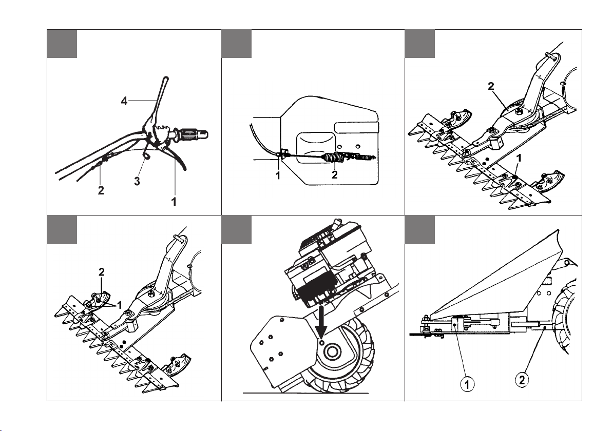
SCHMIERUNG (Abb. 12) Antrieb für Mähbalken alle 8 Arbeitsstunden an Position (1) und (2) mit Fett abschmieren. Wichtig! Messerbalken
und alle beweglichen Teile nach jedem Gebrauch reinigen und schmieren.
WARTUNG FÜR MÄHBALKEN Der Mähbalken zählt zu den am stärksten beanspruchten Teilen. Es ist deshalb selbstverständlich, daß er mit
besonderer Sorgfalt gewartet und eingestellt werden muß. Es empehlt sich den Mähbalken nach jedem Gebrauch zu reinigen. Dazu ist es erforderlich,
das Mähmesser herauszunehmen, damit vor allen Dingen der zwischen Messerklingen und Fingern bzw. Balkenklingen angesammelte Schmutz
gründlich entfernt werden kann. Wird der Mähbalken längere Zeit nicht benutzt, so sollte er mit einem Rostschutzmittel eingesprüht werden.
Obwohl alle Mähbalkentypen weitgehend unempndlich gegen den Eintritt von Steinen und ähnlichen Gegenständen sind, kann es gelegentlich
vorkommen, daß Finger bzw. Balkenklingen und Messerklingen beschädigt bzw. verbogen werden. Deshalb ist es ratsam, bei jedem Nachschärfen des
Mähmessers, was je nach Beanspruchung etwa alle 4-6 Betriebsstunden erforderlich ist, auch den Zustand dieser Teile zu überprüfen. Vorhandene
Beschädigungen sind zu beseitigen und verbogene Finger oder Klingen zu richten. Nur gut ausgerichtete Finger und Klingen gewährleisten einen
sauberen Schnitt. Bei dieser Gelegenheit sollte man auch jeweils die Messerführungen überprüfen und zu großes Führungsspiel durch Nachstellen
ausgleichen. Wichtig für das Nachstellen der Messerführungen ist: Erst eine Führung richtig nachstellen, dann die zweite. Nach dem nachstellen jeder
einzelnen Führung muß das Messer von Hand zügig hin und her zu bewegen sein. Beachten Sie bitte nachfolgend die besonderen Erläuterungen!
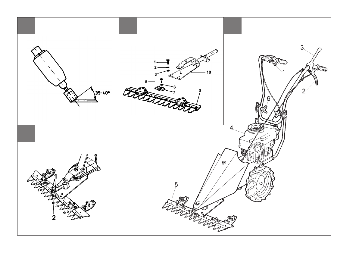
NACHSCHÄRFEN DES MÄHMESSERS (Abb. 13) Je nach Beanspruchung sind die Mähmesser soweit abgestumpft, daß ein
Nachschleifen erfoderlich wird. Zu diesem Zweck wird das Mähmesser aus dem Mähbalken herausgenommen und gesäubert. Es ist zu prüfen, ob
Messerrücken und Messerklingen nicht verbogen sind; andernfalls ist ein Nachrichten erfoderlich. Erst dann sollte mit dem Nachschärfen begonnen
werden. Zweckmäßigerweise verwendet man hierzu einen Handschleifer mit ca. 15000 - 20000 Umdrehungen pro Minute in Verbindung mit einem
topfförmigen Schlekstift mit einem Durchmesser von 25 mm. und einer Länge von ca. 35 mm. Geschliffen wird nur mit der Stirnseite des Schleifstiftes,
und zwar vom Messerrücken zu den Klingenspitzen hin. Messerklingen für Mähbalken benötigen einen Schneidwinkel von 35 - 40°.
AUSTAUSCH DES OBERMESSERS (Abb. 16) Schraube (1) lösen. - Halter (2) enffernen. - Obermesser seitlich herausziehen. Die
Montage erfolgt in umgekehrter Reihenfolge.
BESCHREIBUNG (Abb. 15) 1) Start-Stop, Gashebel - 2) Fahrantrieb, Bedienungshebel - 3) Mähbalkenantrieb, Bedienungshebel - 4) Motor
mit Reversierstarter - 5) Mähbalken - 6) Sterngriffmutter Holmverstellung.
LÄRMEMISSION UND VIBRATIONEN Schallleistungspegel laut Richtlinie En 12733, Leq = 90,8 dB(A), Messunsicherheit K = ±1,2
dB (A). Höchstzulässige Schallwerte ist LWA = 102 dB(A), Messunsicherheit K = ±1,4 dB(A). Höchstzulässigevibrationen an den Lenkholmengemäß
EN12733. Meßwert in = 24,8 m/s2, Messunsicherheit K = ±12,4 m/s2.
D

5
D
nSTÖRUNG
Vor allen Wartungs- und Reinigungsarbeiten Zündkerzenstecker abziehen!
Störung Beseitigung
Motor springt nicht an Benzin auftanken
Gashebel auf Position “START” stellen
Zündkerzenstecker auf die Zündkerze aufstecken
Zündkerze überprüfen, eventuell erneuern
Kraftstoffhahn aufdrehen (nur für Motoren mit Kraftstoffhahn)
Motorleistung lässt nach Luftlter reinigen
Unsauberer Schnitt Messerklingen nachschleifen / erneuern
Schnittspiel nachstellen
Mähwerk / Radantrieb funktioniert nicht Bowdenzug nachstellen
Montage der Räder überprüfen
Keirliemen überprüfen / einstellen und/oder erneurn
Störungen, die mit Hilfe dieser Tabelle nicht behoben werden können, dürfen nur durch einen autorisierten Fachbetrieb behoben werden.

List of contents
Introduction
Conditions of use
Safety measures
Instructions for operating
Assembly
Regulating
Maintenance
Technical Details
Noise
Fault
Serious risk for operator
and bystander safety.
Introduction
Dear Customer:
Thank you for your condence in purchasing our products. We wish you to enjoy using our machines.
The following working instructions have been issued to ensure you a reliable running from the beginning. If you
carefully follow such information the machine will operate with complete satisfaction have a long service life.
Our machines are tested under the most severe conditions before being put into production and are subjected
to strict continuous tests during manufacturing stages.
The present unit has been tested in the country of origin by independent testing authorities in accordance with
strict work norms and safety standards.
When required, only original spare parts must be used to maintain guaranteed function and safety levels.
The operator forfeits any claims which may arise, if the machine shows to be tted with components other than
original spare parts.
Subject to changes in design and construction without notice.
For any questions or further information and spare part orders, we need to be informed of the unit serial number
printed on the side of the machine.
IDENTIFICATION DATA (Fig. 1)
The tag plate with the machine data and Serial N° is on the left side of the scythe mower under the engine.
Note - Always state your scythe mower serial number when you need Technical Service or Spare Parts.
CONDITIONS OF USE AND LIMITATIONS OF USE
This motor mower is designed and built to mow grass on fodder cropped land. The motor mower must only be
used with original equipment and spares. Any use other than that described above is prohibited and will involve,
in addition to cancellation of the warranty, serious risk for the operator and bystanders. The present machine is
suitable for hobby activities only not for professional use.
SAFETY PRECAUTIONS
Attention: Before assembly and putting into operation, please read the operating instruction carefully. Persons
not familiar with these instructions should not use the machine.
1. Before you start mowing, the lawn must be cleared of foreign bodies and also during mowing care
must be taken of these foreign bodies.
2. When starting the motor, the person who is handling the machine must not stand in front of the cutter
bar.
3. When the rotary mower is lifted to be transported, the motor has to be stopped and one has to wait
until the cutting tools come to a standstill. When pushing outside the lawn, the cutting tools are to be
stopped.
6
GB
Translation of original user instructions

4. Maintaining and cleaning works and the adjustment of the cutting height are only allowed when the motor and the cutting tools are stopped
or else with the sparking-plug-cap or power-slupply plug removed.
5. When leaving the mower, the motor must be stopped, or rather the power-supply-plug or ignition key are to be removed.
6. The safety distance given by the guide beams must be observed. The mower must only be operated when the guide beam is in a xed
position.
7. Particular attention is necessary when mowing on slopes and declines.
8. Juveniles under 16 years are not allowed to operate the mower.
9. The operator of the mower must see to it that no other persons are in the working eld.
10. Please take care of the appropriate maintenance, checking, and regrinding of the cutter according to the operating instructions.
11. An expert checking is necessary when, for instance, the mower comes immediately to a standstill by colliding with an obstacle .
12. Rotary mowers with an internal combusition engine must in no case be operated in closed rooms because of the poisoning danger.
13. Never refuel with the motor running. Do not smoke when you refuel. Take an appropriate funnel when you refuel so that no petrol can run
over on the motor and the housing or the lawn.
14. When you are mowing always wear solid shoes, no sandals or suchlike. Caution - there is a great risk of injury to ngers and feet when
the motor is running.
15. Please replace with suitable original blades only. Pay attention to instructions how to replace and regrind the blade.
INSTRUCTIONS FOR OPERATING
INSTRUCTIONS - MOTOR Please follow the motor manufacturer's operating instructions. After starting: Adjust the accelerator lever slowly
into a position between START and STOP which you consider to be suitable operating speed. To switch on cutter bar. To switch on drive mechanism.
DANGER: When mowing beware of foreign bodies and impediments. If you should suddenly run into an unexpected impediment when mowing, please
switch of operating levers immediately. Stop cutter bar. After mowing for a short time switch the mower off and check that all nuts and bolts are tight.
Only mow with a sharp cutting edge and correct adjustment of all blades. To stop: Put the accelerator lever into STOP position.
HOW TO MOUNT THE ACCELERATOR WIRE (Fig. 2) Position the lever (1) on the engine at the end of its stroke as shown by
arrow "A,, in the gure. Move the throttle lever (2) on the handlebar to the end of its stroke as shown by arrow "B,, in the gure. Insert wire (3) into hole
(4), secure the sheath (5) with retainer (6) and screw (7). ATTENTION: in the position "stop,, the throttle lever must stop engine.
BELT STRETCHER DRIVING WIRE (Fig.5) Driving wire is already connected with the belt-stretching spring; have it connected to the
lever on handlebar as follows: Insert the wire (3) and the register (4) in hole cut in the prong. Engage sheath terminal (1) into hole (2).
ASSEMBLING OF THE CUTTER BAR (Fig.10-14) For models equipped with 87 cm. cutting bar please complete the assembly adding
the missing sliding part ( part. 2 – g. 10) you can nd in the accessories envelope. In order to x it please use the 2 screws ( part 1) , the washers
and the nuts you can nd on the cutting bar. Please refer also to chapter : “ how to adjust the cutting bar height”. To x part (7) with the parts (5, 6)
to the (8). Fix the part (10) with the parts (1, 2 and 3) to the (8). After about 2 hours of work to tighten the screws (5).
CORRECT ASSEMBLY OF THE BOWDEN ROD, ENGINE FUEL REGULATION (Fig. 3-4) Insert the opposite end of the
Bowden rod down into the engine fuel lever. Now lightly clamp the jacketed end of the rod. Set the fuel lever on the handlebar to the start position
7
GB

then set the fuel lever on the engine to the start position, right up to the stop point. Following this, denitively x the jacketed end of the rod. Take care
to prevent the rod from bending during the assembly phase. If the fuel lever fails to move freely, lubricate the rod with a few drops of oil and wait a
few minutes to allow the oil to penetrate the casing. Now operate the fuel lever again.
ASSEMBLY OF THE CUTTING BAR TO THE UNIT (Fig. 6) The motor mower has a coupling for quick and easy attachment of
the cutter bar and other accessories. The motor should be shut down and the machine horizontal. Insert the cutter bar pin (1) halfway into its seating
(2). Install the belt (3) in its pulley by moving the guide pin all the way to the end of its travel. Attach the springs to their hooks (5), then to the holes
(7). Replace the cowling (6) with its centering pin. Tighten home the nut with its washer on the cowling.
POSITIONING THE CUTTER BAR DRIVE BELT (Fig. 7) To increase the tension on the cutter bar drive belt between the machine
and the attachment, set the register (2) so that the cutter bar will only begin to move when the control lever is over the halfway mark in its travel. Pull
the left operating lever (1): forward drive.
BELT-STRETCHER CONTROL ADJUSTMENT (Fig. 8) Warning - Tyres should start rotating only when control lever is beyond
halftravel; When lever is pulled to full extent (working position), the beltstretcher load spring (2) should extend by 6 to 8 mm approx. For above de-
scribed conditions be reached, action is to be taken on nut (1 ) set close to the belt stretcher control assembly.
CUTTER BAR HEIGHT ADJUSTMENT (Fig. 10) Having to mow on uneven soils, you must adjust the cutter bar height. Proceed as
follows: - Unloose nut (1), shift sliding block (2) in desired position, tighten nut (1). Perform this step on both sliding blocks.
REGULATING THE KNIFE (Fig. 9) After changing knife or after a certain number of work hours, the knife guide should be regulated by
means of screws (1) and their locknut. To check the results after each regulation, rst remove the cowling and then turn pulley (2) slowly by hand and
check to make sure that the knife is moving easily.
MAINTENANCE Air lter This should be carried out in accordance with the attached motor maintenance instructions.
GEARBOX (Fig. 11) Lube oil: SAE 80. The needed quantity for oil is about 0,18 lt. Check oil level before starting engine. Oil level should he
checked by unscrewing the cap on the side of box. Check oil level every 60 hours of work.
CUTTER BAR TRANSMISSION (Fig. 12) Two greasing points (1-2). Important! Clean and grease blade bar and all moving parts every
time after use.
MAINTENANCE OF THE CUTTER BAR The cutting mechanism is one ot those pieces of agricultural equipment, which is placed
under the most stress. It is abvious, therefore, that it must be particularly carefully serviced and correctly adjusted. It is advisable to clean the cutting
mechanism after each use. To do this the cutting edge must be removed so that the dirt which has collected between the blades and cutting bars can
be completely removed. Should the cutter bar not be in use for a longer period of time it should be sprayed with an anticorrosive agent. Although all
8
GB

types of bar cutting mechanism are by and large resistant to the interference of stones and similar objects, it can occasionally happen that the bars
and blades become damaged or bent. It is necessary, therefore, to check the condition of these parts each time you sharpen the cutting blade - after
4-6 hours of mowing depending on the work load.
Any damage must be made good and bent bars or blades repaired. Only well aligned bars and blades can guarantee a clean cut. At this point the
track directions of the cutting edges should also be checked and too much play in the direction be removed by means of adjustment. lmportant when
adjusting the directions of the cutting edges- adjust one direction rst and then the second. After the adjustment of each single direction the blade
must be able to be freely moved to and fro by hand. Please pay attention to the following particualr instructions!!!
SHARPENlNG THE CUTTlNG BLADE (Fig. 13) When the cutting blades are blunt (this will depend on work load) they must be re-
ground. In order to do this, the cutting blade is removed from the bar and cleaned. It is essential to check whether the backs and edges of the blades are
bent; if so, they must be re-aligned. Only then can sharpening begin. Suitable for this purpose is a hand grinder with about 15000 - 20000 revolutions
per minute, in conjunction with a cup-shaped grinding point with a diameter of 25 mm and a length of about 35 mm. Only the front side (face) of the
grinding point is used in grinding - in a movement from the back of the blade to the bladeís edge. Cutter bar blades need a cutting angle of 35 - 40°.
CUTTING BLADE REPLACEMENT (Fig. 16) Unscrew (1), take the blade coupling out (2) and then remove the blade. To reassemble
the blade, perform these operations backwards. Note - To achieve good cutting, blade must always be sharp.
DESCRIPTION (Fig. 15) 1) Start-Stop operating lever - 2) Drive operating lever - 3) Cutter bar clutching control lever - 4) Engine - 5)
Cutter bar - 6) Handlebar adjusting knob.
TECHNICAL DETAILS Track: 430 mm - Length of cutter bar: 870 mm - Total length: 1350 mm - Total height: 1000 mm - Tires: 2 tires
4.00-6 - Mass: 53 kg. Motor - Cooling: air cooling - Fuel tank: 0,75 Litre. Please consult the relative instruction manual for other technical information
and details about the engine.
NOISE AND VIBRATION LEVEL Measured sound pressure level with En12733, Leq = 90,8 dB (A), with a uncertainty value K = ±1,2 dB
(A). Measured sound power level with En12733, Lwa = 102 dB (A), with a uncertainty value K = ±1,4 dB (A). Handlebar vibration in compliance with
EN 12733. Level max detected = 24,8 m/s2, uncertainty value K = ± 12,4 m/s2.
9
GB

10
GB FAULT
Before performing any maintenance and clearing work operation , please take the spark-plug cap off.!
FAULT FAULT CLEARANCE
The engine does not start check the fuel level, if necessary refuel.
check the throttle to be on START position
check the spark-plug connector to be properly attacched
check the spark-plug condition and if necessary replace it
check the fuel valve to be in the opened position (only for the models showing
such feature)
The engine power goes down the air lter is dirty – please clean it
The grass cut is irregular sharpen or replace the cutting blade
adjust the cutting bar clearance
The cutting bar does not work or the wheels are not turning adjust the cutting bar cable
check the wheels to be fasten to the shaft
check the position and the transmission belts position and condition : realign
position and/or replace them.
In case you are not able to remedy the defect/damage according to a.m. table, please contact an authorized service center only .

11
Indice
Introduzione
Condizioni d'utilizzazione
Norme di sicurezza
Montaggio
Regolazione
Manutenzione
Dati tecnici
Rumore aereo
Guasti
Pericolo grave per l'incolumità
dell'operatore e delle persone
esposte.
INTRODUZIONE
Gentile cliente, lei ha acquistato una nuova attrezzatura. La ringraziamo per la ducia accordata ai ns. prodotti
e le auguriamo un piacevole utilizzo della sua macchina.
Abbiamo creato queste istruzioni per I'uso allo scopo di assicurare, n dall'inizio, un funzionamento privo
d'inconvenienti. Seguite attentamente questi consigli, avrete la soddisfazione di possedere per molto tempo
una macchina che funziona a dovere.
Le nostre macchine, prima di essere fabbricate in serie, vengono collaudate in maniera molto rigorosa e, durante
la fabbricazione vera e propria, sono sottoposte e severi controlli. Ciò costituisce, per noi e per voi, la migliore
garanzia che si tratta di un prodotto di riprovata qualità.
Questa macchina è stata sottoposta a rigorosi test neutrali, nel paese d'origine, e risponde alle norme di
sicurezza in vigore.
Per garantire questo, è necessario utilizzare esclusivamente ricambi originali.
L'utilizzatore perde ogni diritto di garanzia qualora vengono utilizzati ricambi non originali.
Con riserva di variazioni tecnico-costruttive.
Per informazioni e per ordinazioni di pezzi di ricambio si prega citare il numero di articolo e il numero di
produzione.
DATI PER L'IDENTIFICAZIONE (g. 1)
L'etichetta con i dati della macchina e il numero di matricola è sul anco sinistro della motofalce, sotto il motore.
Nota - Nelle eventuali richieste di Assistenza Tecnica o nelle ordinazioni delle Parti di Ricambio, citare sempre
il numero di matricola della motofalce interessata.
CONDIZIONI DI UTILIZZAZIONE - LIMITI D'USO
La motofalciatrice è progettata e costruita per eseguire operazioni di falciatura di terreni erbosi e deve lavorare
esclusivamente con attrezzi e con ricambi originali. Ogni utilizzo diverso da quello sopra descritto è illegale;
comporta, oltre al decadimento della garanzia, anche un grave pericolo per l'operatore e per le persone esposte.
Questa macchina è stata progettata esclusivamente per un uso hobbistico.
NORME DI SICUREZZA
Attenzione: prima del montaggio e la messa in funzione leggere attentamente il libretto istruzione. Le persone
che non conoscono le norme di utilizzazione non possono usare la macchina.
1. Togliere corpi estranei dal prato prima di iniziare le operazioni di falciatura.
2. Nella fase di accensione del motore non sostare nella zona anteriore alle macchina.
3. Per spostare la macchina sulle ruote prima spegnere il motore e attendere I'arresto del dispositivo
di taglio.
4. Tutte le operazioni di pulizia e manutenzione o di montaggio di accessori vanno effettuate a motore
I
Istruzioni d’uso originali

12
spento e con la candela staccata.
5. Abbandonare la macchina solo dopo aver spento il motore e disinserito il dispositivo di sfalcio.
6. Usare la macchina esclusivamente con il manico disposto nella posizione di lavoro. Questo per una completa sicurezza operativa.
7. Lavorando sui pendii, o in prossimità di marciapiedi, usare la macchina con la massima attenzione.
8. L'uso della macchina è vietato ai minori di anni 16.
9. Accertarsi che, durante il lavoro, non sostino estranei nelle immediate vicinanze.
10. Osservate attentamente le istruzioni per l'uso e la manutenzione della macchina e del motore.
11. E' consigliabile l'intervento di un esperto quando si verica un blocccaggio della macchina improvviso.
12. Non accendere e far funzionare la macchina in luoghi chiusi. Il motore a scoppio immette gas di scarico pericolosi nell'aria.
13. Non rabbocare il serbatoio durante il funzionamento. Non fumare in presenza del combustibile. Usare solamente carburante "fresco".
Riempire il serbatoio per mezzo di un adeguato imbuto.
14. Durante il lavoro vanno indossate calzature robuste per maggior protezione. Fate attenzione che il pericolo di ferirsi le dita o i piedi con
la macchina in funzione è molto elevato.
15. Impiegare solo lame di ricambio originali e seguire attentamente le istruzioni per "la sostituzione e aflatura della lame".
ISTRUZIONI D'USO
ISTRUZIONI MOTORE Leggere attentamente le istruzioni allegate relative al motore dopo l'avviamento del motore: Portare la leva acce-
leratore tra la posizione Start e Stop in modo da raggiungere il regime di giri del motore desiderato. Inserimento barra falciante. Inserimento ruota
motrice. Prestare la massima attenzione se si lavora di ostacoli o con corpi estranei sul prato. - Fonte di pericolo! - In caso di accidentale e di impre-
visto ostacolo bisogna tirare immediatamente la leva di comando, in posizione "0". Arrestare la barra falciante: Dopo un breve periodo di utilizzo della
macchina è utile una verica del serraggio delle viti e dei bulloni. Falciare esclusivamente con la barra perfettamente aflata. Per spegnere: portare
la leva comando su posizione STOP.
MONTAGGIO CAVO ACCELERATORE (Fig. 2) Posizionare, a fondo corsa, la leva (1) installata sul motore come indicato dalla frec-
cia "A,, in gura. Portare a ne corsa il manettino comando acceleratore (2) installato sulla stegola come indicato dalla freccia "B,, in gura. Inserire
il cavo (3) nel foro (4), ssare la guaina (5) con l'apposito cavallotto (6) e bloccare con la vite (7). Attenzione: il manettino acceleratore in posizione
"stop", deve spegnere il motore.
CAVO COMANDO TENDICINGHIA (Fig. 5) Il cavo di comando è già collegato alla molla tendicinghia e occorre collegarlo alla leva
installata sul manubrio nel modo seguente: inserire il lo (3) e il registro (4) nel foro tagliato del nasello (5); inserire il terminale (1) nel foro (2).
MONTAGGIO BARRA FALCIANTE (Fig.10-14) Per modelli con barra falciante di cm. 87 completare il montaggio aggiungendo
il pattino mancante (part. 2 - Fig. 10), che viene fornito nella busta accessori. Per ssarlo utilizzare le due viti (part. 1), rondelle e dadi,
già predisposti sulla barra stessa. Vedere anche il capitolo “Regolazione altezza barra falciante”. Fissare il particolare (7) tramite la vite (5) e rondella
(6) alla lama mobile (8). Fissare il part.(10) tramite i part. (1, 2 e 3) alla barra (8).Dopo circa 2 oro di lavoro serrare le viti (5).
CORRETTA REGOLAZIONE DEL TIRANTE BOWDEN, REGOLAZIONE GAS DEL MOTORE (Fig. 4) Inlare nella
leva del gas del motore, dall'alto verso il basso, l'estremità opposta del tirante bowden. Fissare solo leggermente, con l'apposito morsetto, l'estremità
I

13
incamiciata del tirante. Portare la leva del gas sulla stegola in posizione di avviamento.Portare in posizione di avviamento no all'arresto anche la
leva del gas sul motore. Fissare denitivamente l'estremità incamiciata del tirante e fare attenzione che non si pieghi in fase di montaggio. Se la leva
del gas non si muove liberamente, lubricare il tirante con qualche goccia di olio e attendere qualche minuto per permettere all'olio di penetrare nella
incamiciatura. Inne azionare ancora la leva del gas.
MONTAGGIO DELLA BARRA FALCIANTE ALLA MACCHINA (Fig.6) La motofalce è provvista di un attacco che consente
il collegamento rapido e facile della barra falciante ed eventuali accessori. A motore fermo e con la macchina in posizione orizzontale, inserire
completamente il perno della barra (1) nella sua sede (2). Montare la cinghia (3) sulla puleggia portando in ne corsa il perno guida. Agganciare le
molle (4) nei rispettivi ganci (5), poi nei fori (7). Montare il cofano spartierba (6) ssarlo prima sull'antivibrante anteriore poi con l'apposita vite e dado
nella parte superiore.
REGISTRAZIONE DELLA CINGHIA MOVIMENTO BARRA (Fig. 7) Per aumentare la tensione della cinghia del movimento
barra tra macchina e attrezzo, occorre intervenire sul registro (2) in modo che la barra falciante inizi a lavorare solo quando la leva di comando ha
superato metà della propria corsa.
INNESTO DEL MOVIMENTO BARRA FALCIANTE (Fig. 7) Sganciare la levetta di sicurezza (3), quindi abbassare la leva innesto
attrezzo (4).
REGISTRAZIONE DEL COMANDO TENDICINGHIA (Fig. 8) Attenzione - Le ruote devono iniziare a girare solo quando la leva
di comando ha superato la metà della propria corsa. Quando la leva è completamente tirata (posizione di lavoro), la molla di carico del tendicinghia
(2) si deve allungare di circa 6 - 8 mm. Per ottenere le condizioni sopracitate occorre agire sul registro (1) installato nelle vicinanze del comando
tendicinghia.
REGOLAZIONE ALTEZZA BARRA FALCIANTE (Fig. 10) Dovendo falciare su terreni accidentati è necessario regolare l'altezza
della barra falciante. Operare nel modo seguente: - allentare i dadi (1) portare il pattino (2) nella posizione desiderata, serrare i dadi (1). Eseguire
l'operazione su entrambi i pattini.
REGOLAZIONE DELLA LAMA (Fig. 9) Dopo la sostituzione di una lama o dopo alcune ore di lavoro è necessaria la regolazione del
premilama tramite Ie viti (1) e il loro controdado. Per il controllo di ogni regolazione si deve dapprima smontare il cofano, poi fare ruotare Ientamente
con la mano la puleggia (2) e vericare che le lame si muovano liberamente.
REGOLAZIONE STEGOLA (Fig.15) E' possibile regolare la stegola nella posizione più idonea tramite la manopola di serraggio e
regolazione (6).
MANUTENZIONE Filtro aria : pulirlo regolarmente seguendo le istruzioni concernenti il motore.
SCATOLA CAMBIO (Fig.11) Lubricante : Usare olio SAE 80. La quantità di olio necessaria è di circa 0,18 litri. Vericare il livello prima
I

14
dell'avviamento del motore. Il livello dell'olio si verica svitando il tappo sul anco del telaio e va controllato ogni 60 ore di lavoro.
MANUTENZlONE DELLA BARRA FALCIANTE Il tosaerba a barra falciante è certamente una della attrezzature agricole più utilizzate
e richiede pertanto una buona e frequente manutenzione. Si consiglia di pulire a fondo la macchina dopo ogni sfalcio. Per questo è necessario togliere
la lama di taglio in modo da poter ripulire di ogni impurità i denti della barra. Poichè la macchina non viene usata per lunghi periodi è indispensabile
proteggere la barra e lama con sostanze anticorrosive e antiossidanti. Così come per ogni tipo di barra falciante la presenza di impurità o corpi estranei
sul prato toglie inevitabilmente l'aflatura ai denti di taglio. E' utile, pertanto, aflare la lama e controllarne l'integrità dei denti dopo ogni 4 - 6 ore di
utilizzo. Solamente con i denti della lama perfettamente taglienti si può ottenere il taglio ottimale. E' utile inoltre un periodico controllo ed eventuale
messa a punto del "gioco" della lama nei supporti di scorrimento. lmportante per una corretta messa a punto dei supporti: Regolare prima uno e poi
l'altro supporto. Dopo ogni regolazione del singolo supporto il "gioco" della lama deve essere vericato muovendo la stessa con la mano.
AFFlLATURA DELLA LAMA (Fig. 13) In relazione alla intensità di lavoro la lama deve essere periodicamente aflata. A questo scopo la
lama viene rimossa e ben ripulita. Deve essere vericato che i denti e le controlame non siano deformati, dopo di chè si puo procedere all'aflatura.
Generalmente viene utilizzato un aflatore manuale con ca. 15000 - 20000 g/min.1 con punta aflante a testa piena di diametro 25 mm. e lunghezza
ca. 35 mm. I denti del la barra necessitano un angolo di aflatura di 35° - 40°.
TRASMISSIONE BARRA FALCIANTE (Fig.12) Due punti di ingrassaggio (1-2). Importante: dopo ogni uso pulire ed ingrassare la
barra falciante e tutti gli organi in movimento.
SOSTITUZIONE DELLA LAMA FALCIANTE (Fig.16) Svitare le viti (1) estrarre l'attacco lama (2) e slare la lama. Per rimontare
la lama eseguire le operazioni in ordine inverso. Nota :per un buon taglio la lama deve essere sempre aflata.
DESCRIZIONE (Fig.15) 1) Leva comando acceleratore - 2) Leva comando della trasmissione ruote motrici - 3) Leva comando innesto barra
- 4) Motore - 5) Barra falciante - 6) Manopola regolazione stegola.
DATI TECNICI Scartamento: 430 mm. - Larghezza barra 870 mm.- Lunghezza complessiva 1350 mm. - Altezza complessiva 1000 mm.
- Pneumatici: 2 gomme 4.00-6 Massa: 53 Kg. - Motore raffreddato ad aria. - Capacità del serbatoio 0.75 litri. Per altri dati tecnici e particolari del
motore vedere l'allegato manuale istruzione dello stesso.
RUMORE AEREO E VIBRAZIONI Valore di pressione acustica secondo EN 12733 Leq = 90,8 dB (A), valore d’incertezza della misura
K = ±1,2 dB (A). Valore di potenza acustica al posto di lavoro secondo EN 12733 Lwa = 102 dB (A), valore di incertezza della misura K = ± 1,4 dB
(A). Vibrazioni alle stegole secondo EN 12733. Valore max rilevato = 24,8 m/s2. Valore d’incertezza nella misura K = ±12,4 m/s2.
I
Table of contents
Languages:
Other MTD Trimmer manuals

MTD
MTD H 15 User manual

MTD
MTD 800 Series User manual

MTD
MTD Yard Machines Y28 User manual

MTD
MTD EB 1000 User manual

MTD
MTD Yard Machines LT31CS User manual

MTD
MTD Yard Machines Y700 User manual

MTD
MTD Yard-Man YM90BC User manual

MTD
MTD Series 790 User manual

MTD
MTD TrimmerPlus BT720r User manual

MTD
MTD Yard Machines Y725 User manual