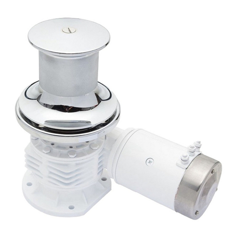
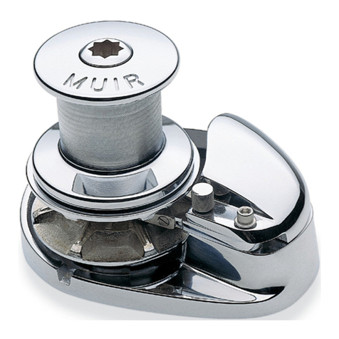
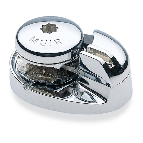
Muir VC-800 User manual

T H E W O R L D P O W E R I N A N C H O R I N G S Y S T E M S
VC800 www.muir.com.au 1
Updated 18/11/2013
VC-800
VERTICAL INLINE CAPSTAN

T H E W O R L D P O W E R I N A N C H O R I N G S Y S T E M S
VC800 www.muir.com.au 2
Updated 18/11/2013
Contents
INTRODUCTION........................................................................................3
IMPORTANT INFORMATION ....................................................................3
SAFE OPERATION.....................................................................................3
INSTALLATION INSTRUCTIONS.................................................................3
HANDY HINTS ...........................................................................................3
TECHNICAL DETAILS ................................................................................4
ELECTRICAL ..............................................................................................4
Circuit breaker ..................................................................................4
Deck Switches ....................................................................................4
Isolating Switch ..................................................................................4
Batteries...............................................................................................4
Solenoid Installation ..........................................................................5
OPERATING INSTRUCTIONS ....................................................................5
Anchoring: ..........................................................................................5
MAINTENANCE AND SERVICING...........................................................6
Servicing..............................................................................................6
Line Care .............................................................................................6
Rope/Chain Splice. ...........................................................................6
CORROSION PROTECTION.....................................................................7
ELECTRICAL INFORMATION/DIAGRAM/SCHEMATIC ………….. 7-11
DECK TEMPLATE (PLACED IN THE MANUAL AS A SEPARATE PAGE)

T H E W O R L D P O W E R I N A N C H O R I N G S Y S T E M S
VC800 www.muir.com.au 3
Updated 18/11/2013
INTRODUCTION
Thank you for purchasing a Muir Windlass. Muir go to great lengths to develop anchoring systems that not only
meet all your performance and safety requirements, but at the same time are designed with a style and finish
that enhances the aesthetics of your vessel. With Muir’s commitment to quality and the use of superior
materials and processes we know you will be pleased with your investment, and rest assured that through the
correct installation, operation and maintenance your new Muir Windlass will give you years of reliable
performance.
IMPORTANT INFORMATION
To avoid damage to the capstan or vessel when retrieving the anchor, it is a preferred practice to mark the
rope/chain at approximately 5-meter intervals from the anchor, to alert the operator to the anchor position.
Under no circumstances should the windlass be operated if it is stalled or overloaded.
SAFE OPERATION
•Ensure that hands, feet, hair and clothing are kept clear of the windlass and other loose gear when in
operation.
•The capstan should never be used for lifting people aloft.
•Do not use a capstan as a bollard for mooring, towing or being towed.
INSTALLATION INSTRUCTIONS
Locate the capstan in a suitable position on the deck so there is no interference from other ropes or objects
(the rope has a clear lead to the winch), so that there is working room and you can tail the line confortable.
Ensure that there is sufficient room to run the electrical cables to the winch underneath the deck.
If the deck is angled or curved a suitably shaped mounting block will be required to spread the load evenly
over the deck surface and mount the winch on a level and even footing. Depending on the thickness of the
deck, a suitable spacer below deck may be required to mount the winch. Place the shaped mounting block
(if required) onto the deck. Use the layout template dimensions to mark the hole centres and then drill/cut out
the holes.
Apply an appropriate sealant to the base plate and mounting block (if required), taking care to align
mounting holes when assembling. For Aluminium or Steel hull vessels, it is important to insulate the
capstan with a non-conductive gasket to avoid corrosion. This also applies below deck with the
mounting bolts, nuts and washers. Where the deck construction is light or of foam sandwich construction,
a plywood stiffener of at least 16mm (5/8") should be fitted to the underside of the deck to spread the
load. Install and tighten mounting bolts.
For recommended Electrical installation, please review electrical section.
HANDY HINTS
Ensure sufficient room to run electric cables to the capstan winch. Follow the instructions above including
underdeck stiffening, alignment, mounting blocks and sealing procedures.
Position the capstan carefully checking desired rope path before mounting capstan to your deck.

T H E W O R L D P O W E R I N A N C H O R I N G S Y S T E M S
VC800 www.muir.com.au 4
Updated 18/11/2013
TECHNICAL DETAILS
Motor 600w x 12v Permanent Magnet Motors
Capstan High tensile bronze, chrome plated
Base Plate Marine grade hard anodised and sealed aluminium
Gearbox Two stage balanced epic clic
Deck studs Supplied with nuts in stainless steel
Weight 8kg (18lbs)
Rotation Clockwise or right hand.
Brake Auto action roller clutch - will not run back
Cable Size Boats to 11 meters (36ft) use 25 mm
2
- 3awg
Accessories Deck switch with flip top cover
Muir circuit breaker
Winch
sizing
There are no absolute rules about winch size to boat size. This product is designed for use on
t pical private pleasure craft. Winch / boat sizes shown are based on installations that have
proved satisfactor for man ears.
ELECTRICAL
See Wiring Diagrams for wiring instructions.
Circuit breaker (must be fitted to ensure warranty)
If the drum winch is overloaded or stalled the circuit breaker automatically cuts off power to the winch
and protects the wiring and motor. The circuit breaker should not be used as an isolating switch, for safety
reasons.
Deck Switches
are best located to either port or starboard or directly behind the capstan in a position where it
can be easily reached with your foot or knee, preferably where you can view the anchor and chain coming
aboard.
Isolating Switch
should be fitted in an accessible position for safety, ideally close to the battery or switches. The
isolating switch is not a circuit breaker.
Batteries
are best located as close to the capstan as possible. Larger cables will reduce the voltage drop
to the motor and the heat generated when operating the winch. Small diameter cables drop voltage
considerably. Use the following table as a guide to your required wire size: (Based on 1500W 12V Motor)
Distance from battery to motor
(m)
Cable Size
(mm
2
) AWG
Cable Core Diameter
(mm)
< 8 (26’) 25 3 7 (17/64”)
9 – 12 ( 29’ – 39’ ) 35 2 8 (5/16”)
13 – 18 ( 42’ – 60’ ) 50 1/0 9 (23/64”)

T H E W O R L D P O W E R I N A N C H O R I N G S Y S T E M S
VC800 www.muir.com.au 5
Updated 18/11/2013
Solenoid Installation
We recommend that the solenoid is installed in an upright position, where it has no exposure to sea water
and in close proximity to the electric motor of the winch.
For wiring information, please refer to the wiring diagram/schematic.
WINCH MODEL MOTOR SIZE MOTOR TYPE
VC800 600W 2 POLE
OPERATING INSTRUCTIONS
It is adviseable to “mark” the anchor end of the chain/rope at 2 and 5 metre (6.5’ & 16.5’) intervals which will
enable the operator to judge when the anchor is almost up.
Anchoring:
Lower the anchor as you reverse the boat, this allows the anchor and chain to layout properly on the
sea bed. Lower the anchor until the rope is slack and/or you are in the right position, once there it is
recommended to tie off the rope to a cleat or bollard, or use a snubber.
To retrieve/raise the anchor, stand or kneel behind the winch and simply wind up to three turns (maximum) of
line or sheet around the drum in a clockwise direction. Maintain a light “tailing” pull onto the free end and
start the capstan. As the capstan rotates, lightly pull the line hand over hand keeping up with the speed of
the winch. The capstan does all the hard work for you. Stop and hold at any time. Do not use your hands or
feet on the anchor side of the capstan drum to adjust the rope as it may become caught and entangled in
the winch drum.
When recovering your anchor, first start the engine.
In strong winds, tides, currents or in deep water, use
a little engine power to come up over the anchor
as the capstan is used. Never stall the capstan and
do not run it at low speed for any extended time.
Use one continuous and smooth recovery and do
not repeatedly start/stop. If the anchor is stuck, use
a little engine power and the weight of the boat to
break it free.
Also take care not to run over the anchor rope and entangle it in your prop or rudder. Go gently with the last
two metres of retrieving the anchor, rather than waiting for the anchor to fly up over the roller and bang tight,
putting excessive load onto the bow roller, winch and fore deck. When the weather is rough, anchoring
overnight or traveling, it is not recommended to use the casptan as a mooring bollard!! Secure the rope around
a cleat or bollard, or use a snubber to take the load.

T H E W O R L D P O W E R I N A N C H O R I N G S Y S T E M S
VC800 www.muir.com.au 6
Updated 18/11/2013
MAINTENANCE AND SERVICING
Servicing
Every 6 months, remove centre screw from top of the capstan drum and lift drum off.
Lightly grease the synthetic bearings under the drum.
Smear a little grease on the O ring seal in the top outer cap, assemble and tighten firmly.
The motor is made of steel and may corrode if the paint system is damaged.
Check the motor regularly and keep dry and clean.
In “dry” installations, spray the motor regularly with a water repellant (CRC or WD40).
In damp or “wet” installations, including situations where a lot of condensation takes place, treat the motor
and terminals regularly with CRC “soft seal” or similar.
Check all terminals in the system and protect as described above.
In the case of Work and Charter Vesels we suggest it is carried out more frequently.
Line Care
Muir winches are designed to run on 3-strand nylon line (supplied by Muir) which has been specially
treated with fabric softener to prevent it from hardening. It is recommended to soak your rope in fresh
water containing fabric softener every 3 months.
Rope/Chain Splice.
1. To stop rope unravelling, seize rope 400mm(16") from end with whipping twine. Unlay strands.
2. After placing 20mm (3/4") of heat shrink sleeve tubing through
the last link of chain, pass one strand of rope through sleeve and
chain from one side and the other two strands of rope from the
opposite side. (See illustration).
3. While pulling all three strands tight, shrink the sleeve tightly onto
the rope using a hairdryer / fan heater or by immersing in boiling
water.
4. Remove seizing and complete back splice in normal manner for two full tucks. With a hot knife pare down
the three strands by 1/3 and insert two further tucks. Pare down by another1/3 and finish with two tucks.
Cut any remaining tails.

T H E W O R L D P O W E R I N A N C H O R I N G S Y S T E M S
VC800 www.muir.com.au 7
Updated 18/11/2013
CORROSION PROTECTION - for long life (general notes for all winches).
The motor and some underdeck parts of your winch are manufactured from materials that require protection
from the marine environment. Paint and other protection systems are applied at time of manufacturer, but
additional protection and regular inspection is necessary after installation.
Immediatley after installation we recommend that the winch is tested. Reversing winches should be run in
forward, reverse and manual modes. Rope only winches will only run one way unless ordered otherwise.
Observe polarity indicated by +/- lables on motor. Check all terminals and fastenings are firmly secured. Coat
all underdeck surfaces and terminals with CRC ‘Softseal’, automotive underseal or similar. Control equipment
should never be installed in damp positions such as the chain locker, but, if necessary, control equipment will
need protection too.
Service checks. Check motors and underdeck parts regualary for signs of corrosion and take necessary action
immediately. Above deck items need maintenance too, including cleaning, greasing/oiling per instructions
issued with the winch. If cone cutches (where fitted) are found to stick, release clutch nut and give one of the
gypsy teeth a smart rap with a hard wood or brass drift. When the clutches free up, a very light spray with CRC
/ WD40 will help prevent further sticking.
WARNING. Motor, brake, gearbox assembly should never be removed or fastenings loosened during
installation. Some fastenings are sealed with a locking compound and warranty may be void if any seal is
broken. If a fault is suspected during the warranty period DO NOT remove any parts or attempt a repair. Return
the complete unit to the factory via supplier with evidence of purchase and detail of problem experienced.
FAILURE or DAMAGE due to improper maintanence is not covered by warranty.
ATTENTION !
VC800 Capstan will ONLY work in clockwise direction.
Always connect Positive (+) Terminal on the Battery
to the Positive (+) Terminal on VC800 Electric Motor.
Always connect negative (-) Terminal on the Battery
to the negative (-) Terminal on VC800 Electric Motor.
If wired incorrectly it will damage
the Electric Motor and VOID the Warranty

T H E W O R L D P O W E R I N A N C H O R I N G S Y S T E M S
Teminal Warning VC800 18/11/2013
www.muir.com.au
Do not over tighten terminal nuts.
It may cause internal damage.
Ensure bottom nut is held with a spanner
when tightening top nut.
Please apply this method to all
solenoids, circuit breakers
and motor terminals.
Turn top spanner
clockwise to tighten
Hold bottom
Spanner firm
Correct method using 2 spanners. Incorrect method using 1 spanner.


THIS PAGE INTENTIONALLY LEFT BLANK

THIS PAGE INTENTIONALLY LEFT BLANK

T H E W O R L D P O W E R I N A N C H O R I N G S Y S T E M S
VC800 www.muir.com.au
Updated 18/11/2013
Warranty
Limited for period of Three years (First Owner)
We warrant each new product manufactured by us to be free from defects in material and workmanship for a period of 3
years (first Owner).
This warranty shall become effective only upon receipt of a completed warranty registration, which shall identify the product
so registered by serial number. This warranty shall remain in effect for a period of three (3) years from the date of purchase.
For vessels in charter or hire the warranty is one (1) year due to various operators and overloading which may occur.
Conditions
While this warranty applies to defects in material and workmanship, it does not apply to:
• Normal worn parts or to damage caused by neglect, lack of maintenance, accident or improper service/installation or
service by persons other than an authorised Muir representative.
• Muir shall not be responsible for failures due to products being used in applications that they are not intended for, or
exceed the products performance specifications.
• For warranty claim, defective product must be returned to Muir for inspection.
• Muir will not be responsible for freight charges, removal or installation labour on warranty claims.
• Damage due to unsatisfactory storage or use of equipment prior to installation in the approved/intended manner.
Exclusions
Warranty is limited to twelve months for:
• Electric motors / controls / equipment
• Hydraulic pumps / controls /valves
• Weather seals
• Use on charter/hire/commercial boats
All incidental and/or consequential damages are excluded from this warranty. Warranties of merchantability and fitness are
excluded from this warranty. Implied warranties are limited to the life of this warranty. Some countries do not allow
limitations on how long an implied warranty lasts or the exclusion or limitation of incidental or consequential damages, so the
above may not apply to you.
We reserve the right to improve the design or materials used on any product without assuming any obligation to modify any
product previously manufactured or used.
Liability
Muir Engineering liability under this warranty shall be to the exclusion of all other warranties or liabilities (to the extent
permitted by law). In particular (but without limitation):
Muir Engineering shall not be liable for:
Any indirect or consequential loss including (without limitation) any loss of anticipated profits, damage to reputation or
goodwill, loss of expected future business, damages, costs or expenses payable to any third party or any other indirect
losses. Any damage to yachts or equipment. Death or personal Injury (unless caused by Muir Engineering negligence).
- - - - - - - - - - - - - - - - - - - - - - - - - - - - - - - - - - - - - - - - - - - - - - - - - - - - - - - - - - - - - - - - - - - - - - - - -
WARRANTY REGISTRATION CARD
Return To
MUIR ENGINEERING PTY. LTD.
100 Browns Rd, Kingston
Tasmania, Australia, 7050
Customer / Company Name: Winch Model:
VC800
Contact (if Company): Serial Number:
Address: Purchase Date:
dd / mm / yyyy
Purchased From:
Phone / Email: Invoice Number / Receipt Number / Proof of Purchase:

THIS PAGE INTENTIONALLY LEFT BLANK

T H E W O R L D P O W E R I N A N C H O R I N G S Y S T E M S
VC800 www.muir.com.au
Updated 18/11/2013
Head Office:
100 Browns Road
Kingston, Tasmania, 7050
Australia
Tel Int: +61 (0)3 6229 0600
Fax Int: +61 (0)3 6229 7030
Email: sal[email protected].au
www.muir.com.au
SERIAL NUMBER:
© 2013 Muir Engineering Pty. Ltd.
Muir reserves the right to alter specifications without notice.
All rights reserved.
While all due care and attention has been taken in the preparation of this manual no responsibility shall be
taken for errors or omissions.
Table of contents
Other Muir Marine Equipment manuals
Popular Marine Equipment manuals by other brands

Kongsberg
Kongsberg EA640 Quick installation guide

Stahl
Stahl C&S YA90 Series operating instructions

E2S
E2S BExCS110-05D-PDC012 instruction manual

Audiovox
Audiovox AquaTronics MS1500 Owner's manual and installation guide

System Sensor
System Sensor B200S-LF Installation and maintenance instructions

Facnor
Facnor FX+ 900 Installation & use instructions