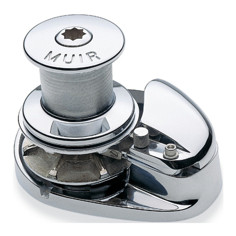
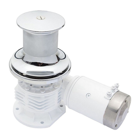
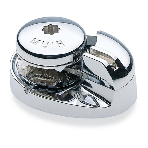
Muir VRC4500 Quick guide

1
VRC4500 - VERTICAL WINDLASS
INSTALLATION AND INSTRUCTION MANUAL
(MUST BE READ PRIOR TO INSTALLATION AND OPERATION)
DESIGNED, MANUFACTURED AND SUPPLIED BY:
Muir Engineering Group Pty Ltd (HEAD OFFICE)
100 Browns Road, Kingston 7050 Tasmania Australia Tel:
ITN’L (61-3), AU (03) 6229 0600
Fax: ITN’L (61-3), AU (03) 6229 7030
Email: [email protected] Web: www.muir.com.au
T h e w o r l d p o w e r i n w i n d l a s s e s & a n c h o r i n g s y s t e m s

2
CONTENTS
SECTION 1 SYNOPSIS
Scope of supply
SECTION 2 GENERAL DESCRIPTIONS
Line Type
Gearbox Description
Motor Description
SECTION 3 WINDLASS INSTALLATIONS
Installation
Operation
Safety
Maintenance
Lubrication
Bolt Torque Settings
SECTION 4 APPENDIXES
Motor Specifications
Gearbox specifications
Exploded / general layout drawings
Warranty

3
SCOPE OF SUPPLY
Equipment Supplied includes the following items
GENERAL DESCRIPTION
The VRC4500 Model Vertical Windlass is powered by an electric motor through a single stage
worm drive reduction. The windlass consists of a gypsy and capstan mounted on a stainless steel
drive shaft supported by low friction bearings, mounted on a Stainless Steel base plate.
The clutch handle fitted into the Clutch Nut is used to de-clutch the drive and free wheel the chain
gypsy. The brake band controls the run of the anchor and chain. The capstan is keyed directly to
the drive shaft and the gypsy is driven by engaging the clutch. All components are of bronze or
stainless steel construction.
LINE: 12.5mm U2 (Kenters)
GEARBOX:
Manufacturer: STM
Description: Single Stage 90 Degree Worm Wheel Gearbox
Model: RMI 110 F2
Ratio: 70:1
MOTOR:
Manufacturer: WEG
Model: 440V / 4kW / 3Ph / 50Hz
ITEM / FEATURE
DESCRIPTION
1
6 x VRC4500 Vertical Windlass
Fitted with a single gypsy.
Gypsy to suit 12.5mm U2 STUD LINK
Fluted Capstan Finish
Electric Motor
Cone Drive
2
Polished 316 Stainless Steel Finish
3
Stainless Steel Clutch handle
4
35 degree Brake
5
Installation manuals

VRC4500/5000 VERTICAL WINDLASS INSTALLATION
4
LOCATING THE WINDLASS
When installing the windlass it is important to consider the
following requirements for efficient operation of the whole
anchoring system.
A clear and horizontal Chain Path
Correct Positioning and Locker Depth
Ma imizing the Wrap of Chain around the Gypsy
Position of the Motor and Gearbo Under deck
Insulation of Dissimilar Metals
The windlass should be positioned centrally over the chain
locker. This helps to ma imize the fall of chain down to the
locker as it piles up when retrieving the anchor (See the fall
depth table).
It is a common mistake to locate the windlass too far
forward, or too close to the bulk head, where there is
insufficient room for the chain and anchor stowing. In
installations where this is not possible a length of 'lead in'
tube with a belled end and a bore of at least 2 times the
chain width can be used to guide the chain to the centre of
the chain locker. This e tension needs to be a minimum of
45
0
to 90
0
from the under deck. Angles less than 45
0
will
increase chain drag within the tube.
The gear drive can be fitted in multiple positions to allow the
chain to fall away from the motor. If the motor is positioned
near the falling chain then the lead in tube is also
recommended to protect the motor from water.
Chain Size
Minimum Fall De th To
To Of Hea ed Chain
Up to 1/2” (13mm) 36” (914mm)
5/8” to 7/8”(16 to 22mm) 48” (1220mm)
1” (25mm) and Above 48” (1220mm) or Greater
When fitting the base plate all mating surfaces should be
coated with sealant, to ensure enough is applied allow it to
squeeze out as the mounting bolts are tightened.
After fitting the base plate in the desired position the
windlass can be reassembled using the assembly
instructions on the following page.
The chain pipe should be fitted last making sure to match the
height of the chain from the gypsy. Ideally this should line up
with the chain after it has wrapped 180 degrees around the
gypsy; this angle of wrap should not be less than 140
degrees for the correct operation. Refer to diagram in
appendi for correct chain pipe and peeler setup
If the windlass is to be mounted on a steel or alloy deck an
insulator, preferably some form of rigid plastic must be used
to avoid contact of dissimilar metals. It is also advisable to
insulate the mounting bolts with plastic sleeves.
If the vessel has a curved deck an appropriately shaped
mounting block must be used.
Reassemble the windlass, fitting the shaft and top assembly
complete, (refer e ploded view) using a waterproof grease to
lubricate all parts and running gear.
It is important to thoroughly lubricate all mating surfaces with
grease suitable for marine applications before use. As the
windlass will be operating in an e tremely corrosive
environment it is also highly recommended that corrosion
protection be used on the e ternal surfaces of the motor,
gear drive and adaptor, and also in any areas where water
may lie to protect against moisture in the chain locker (See
the maintenance section for additional information).
ELECTRICAL INSTALLATION
Ensure all wiring is completed as per supplied wiring
diagram and that all circuit components and wire is suitable
for the system rating. To maintain the manufacturer’s
warranty on the windlass a suitably rated overload protection
must be installed to protect the motor.
HYDRAULIC INSTALLATION
To ensure minimal pressure loss or heat build up, it is
recommended that hydraulic piping of the following minimum
size is used.
Length of Line
Pi e S
ize (Outside Diameter)
Up to 30’ (9.1m) 5/8” (16mm)
Over 30’ (9.1m) 3/4” (19mm)
To maintain the manufacturer’s warranty on the windlass a
pressure relief valve must be installed to the hydraulic circuit.
Muir also recommends that a counterbalance valve be
installed to the hydraulic motor to prevent runback.
4500

VRC4500/5000 VERTICAL WINDLASS OPERATION
5
Note 1: For round base model windlasses the brake locator is mounted to the deck.
Note 2: Tighten and slacken brake band to positions to centralize brake band position before drilling locator to deck.
This operation can be performed from above and below deck. The deck plate in each case remains in place
The reduction gear and motor assembly can be removed by first undoing the lock bolt located under the gear
drive in the end of the main shaft.
By undoing the bolts located between the gear drive and
adaptor flange the reduction assembly can be removed.
(The adaptor is bolted internally to the base plate.)
To remove the drive shaft and top assembly, first to remove
the drive key from the lower section of the shaft, the top
assembly and running gear can be lifted clear of the base
plate supported by the chain gypsy
DISMANTLING THE TOP ASSEMBLY
COMMISSIONING PROCEDURE
1. Ensure all electrical wiring to controls and motor is completed to the specification outlined in the wiring
diagram supplied.
2. Grease all nipples as shown on the diagram above. (And as describe in page 8).
3. Check that the gear drives is filled with the correct quantity and type of oil as detailed in the Appendi .
4. Disengage the clutch by turning clutch nut anti clockwise.
5. Disengage the brake using hand wheel.
6. Rotate the motor by power or by the motor shaft to ensure windlass is free to rotate.
7. Start the windlass with no load and ensure that direction of rotation is correct and check that windlass is
operating with no undue noise or vibration.
8. Continue running-in the motor and gear drive for 30 minutes. Re check gear drives oil level and grease points.
9. If the torque limiter is present by the factory refer to gearbo information for detail on adjustment
1 The base must secured to the deck using the bolts (studs)
provided. The deck structure must be suitable reinforced to
support the winch. It is important to stiffen the underside of
the deck with a doubling plate.
2 Remove chain pipe and spacer (if fitted) from deck.
Note: During pre-assembly chain pipe, make sure the peeler
lines up with core of the gypsy to ensure correct fitting.
3 Remove bolt and plug from top of the clutch nut.
4 Wind the clutch nut off the shaft anti clockwise then remove
the capstan.
5 Remove the chain gypsy.
6 Remove brake 45 degree hand wheel assembly.
7 Lift the brake band after releasing bracket. Taking care to align
with the brake mount.
8 Lift off bottom cone and remove seal.
9 Remove reduction bo and shaft from deck adaptor by
removing adaptor bolts
10
Remove gearbo adaptor bolts and separate base and
adaptor. Undo the motor mounting bolts and remove the
motor and torque limiter (if supplied). Undo gearbo bolts on
gearbo adaptor and lift off the gearbo .
For gearbo lifting, refer to section 4 – gearbo specification.
GREASE NIPPLES (IF FITTED)
SEE NOTE IN LUBRICATION
SECTION
GREASE NIPPLE
Table of contents
Other Muir Marine Equipment manuals