Multimetrix CT 51 User manual
C
C
CT
T
T
5
5
51
1
1
C
C
Ca
a
ab
b
bl
l
le
e
e
T
T
Te
e
es
s
st
t
te
e
er
r
r
R
R
RJ
J
J-
-
-4
4
45
5
5,
,
,
R
R
RJ
J
J-
-
-1
1
11
1
1,
,
,
U
U
US
S
SB
B
B
B
B
B,
,
,
I
I
IE
E
EE
E
EE
E
E
1
1
13
3
39
9
94
4
4,
,
,
B
B
BN
N
NC
C
C
N
N
No
o
ot
t
ti
i
ic
c
ce
e
e
d
d
de
e
e
f
f
fo
o
on
n
nc
c
ct
t
ti
i
io
o
on
n
nn
n
ne
e
em
m
me
e
en
n
nt
t
t
U
U
Us
s
se
e
er
r
r’
’
’s
s
s
m
m
ma
a
an
n
nu
u
ua
a
al
l
l
B
B
Be
e
ed
d
di
i
ie
e
en
n
nu
u
un
n
ng
g
gs
s
sa
a
an
n
nl
l
le
e
ei
i
it
t
tu
u
un
n
ng
g
g
L
L
Li
i
ib
b
br
r
re
e
et
t
tt
t
to
o
o
d
d
d’
’
’i
i
is
s
st
t
tr
r
ru
u
uz
z
zi
i
io
o
on
n
ni
i
i
M
M
Ma
a
an
n
nu
u
ua
a
al
l
l
d
d
de
e
e
i
i
in
n
ns
s
st
t
tr
r
ru
u
uc
c
ci
i
io
o
on
n
ne
e
es
s
s
CHAUVIN ARNOUX
190, rue Championnet
F – 75876 Cedex 18 - PARIS
Tél. 33 (0)1.44.85.44.85 - Fax 33 (0)1.46.27.73.89
691064A00 - Ed. 04 - 08/04

Français
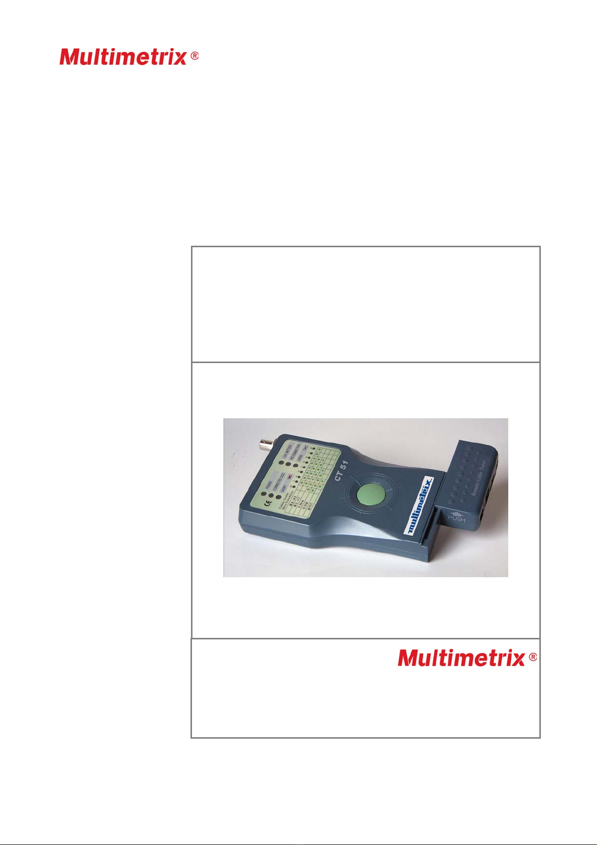
2 CT 51
Instructions générales
Introduction Félicitations pour votre achat.
Cet instrument fait partie de la gamme MULTIMETRIX.
Lire les instructions de sécurité suivantes avant de l’utiliser et se rapporter
aux messages de sécurité, afin d’éviter les accidents corporels, tels que
les brûlures et chocs électriques.
Symbole Il est impératif de suivre les indications précédées du symbole .
Sécurité Utilisez cet appareil uniquement dans le cadre de son application.
Pour travailler en
sécurité ….
• Ne pas utiliser dans les armoires électriques.
• Ne travaillez jamais au-delà des plages de tension max. indiquées.
• Vérifiez l’état de fonctionnement de l’appareil avant emploi.
• N’utilisez pas l’appareil, si celui-ci est détérioré.
• N’utilisez jamais votre instrument dans un environnement humide ou
poussiéreux.
• Ne démontez pas le boîtier.
• Seule la trappe à pile peut être ouverte
• N’utilisez jamais l’appareil, trappe à pile ouverte.
Garantie Ce matériel est garanti contre tout défaut de matière ou vice de
fabrication, conformément aux conditions générales de vente.
Durant la période de garantie (1 an), l'appareil ne peut être réparé que
par le constructeur, celui-ci se réservant la décision de procéder soit à la
réparation, soit à l'échange de tout ou partie de l'appareil.
En cas de retour du matériel au constructeur, le transport aller est à la
charge du client.

Français
CT 51 3
Instructions générales (suite)
Garantie (suite) La garantie ne s’applique pas suite à :
1. une utilisation impropre du matériel ou par association de celui-ci
avec un équipement incompatible
2. une modification du matériel sans autorisation explicite des services
techniques du constructeur
3. l’intervention effectuée par une personne non agréée par le
constructeur
4. l'adaptation à une application particulière, non prévue par la
définition du matériel ou par la notice de fonctionnement
5. un choc, une chute ou une inondation.
Déballage et
ré-emballage
L’ensemble du matériel a été vérifié mécaniquement et électriquement
avant l’expédition.
Toutefois, il est conseillé de procéder à une vérification rapide pour
détecter toute détérioration éventuelle lors du transport.
Si tel était le cas, faites alors immédiatement les réserves d’usage
auprès du transporteur.
En cas de réexpédition, utilisez l’emballage d’origine et indiquez, par
une note jointe à l’appareil, les motifs du renvoi.
Maintenance
Vérification
métrologique
Comme tous les appareils de mesure ou d'essais, une vérification
périodique est nécessaire.
Renseignements et coordonnées sur demande :
Tél. 02.31.64.51.55 - Fax 02.31.64.51.09.
Entretien • Nettoyez périodiquement votre instrument avec un tissu humide
imprégné d'eau savonneuse.
• N’utilisez pas de matières abrasives ou contenant des solvants.
Pile Pour ouvrir le logement pile, appuyez sur le couvercle de la trappe à
l’arrière du boitier de l’unité principale tout en le glissant sur la droite.
Retirer la pile usagée et la remplacer en respectant la polarité.
Conservez la pile hors de portée des enfants.
Stockage Si vous n'utilisez pas votre instrument pendant une période supérieure à
60 jours, retirez la pile et stockez-la séparément.

Français
4 CT 51
Description de l’instrument
Mode d’emploi
Précautions
d’emploi
- Ne raccordez pas le testeur sur un câble alimenté.
- Ne testez pas plus d'un câble à la fois.
Mode d’emploi 1 - Branchez l’unité secondaire à une extrémité du câble à tester et l’unité
principale à l’autre extrémité.
Pour une mesure sur une installation câblée, nous vous conseillons de
détacher l’unité secondaire de l’unité principale en faisant glisser celle-
ci par une légère poussée selon l’indication portée sur le boîtier.
2 - Appuyez sur le bouton poussoir vert au centre de l’unité principale.
3 - Lisez le résultat sur les LEDs de contrôle et interprétez-les selon les
indications données au §. LED de contrôle sur l’unité principale.
Nota Sur les prises RJ-45, le test s'effectue sur 8 LEDs, ou sur 9 LEDs si
l’instrument est équipé d’une liaison de terre.
Les prises RJ-11 comportant 6 fils, le résultat se lit sur 6 LEDs.
En liaison 1394, le résultat se lit sur 7 LEDs.
Les prises USB étant en 4 fils + masse, le résultat se lit sur 5 LEDs.
La prise BNC se lit sur 2 LEDs.

Français
CT 51 5
Description de l’instrument (suite)
Illustration
Face avant
Légende pour
l'unité principale
1.
Bouton poussoir de commande de test (vert)
2.
LEDs de contrôle (voir plan détaillé)
3.
Connecteur RJ-45 pour le test des câbles LAN et INTERNET 10BASE-T,
EIA/TIA-568/568B, AT&T268A, Token Ring et tout autres systèmes de
câbles équipés d'un connecteur RJ-45.
4.
Connecteur RJ-11 pour le test des câbles type téléphone, PhonNet et
tout autre système de câbles équipé d'un connecteur RJ-11.
5.
Connecteur IEEE 1394 pour le test des câbles équipés d'un connecteur
IEEE 1394.
6.
Connecteur USB B pour le test des câbles de liaison USB et tout autre
système de câbles équipé d'un connecteur USB.
7.
Connecteur BNC pour le test des câbles de liaisons de terminaux
ETHERNET 10BASE-2/10BASE-5.
Légende pour
l'unité secondaire
8.
Branchement pour l'autre extrémité du connecteur RJ-45
9.
Branchement pour l'autre extrémité du connecteur RJ-11
10. Branchement pour l'autre extrémité du connecteur IEEE 1394
11. Branchement pour l'autre extrémité du connecteur USB B
1. Bouton
p
oussoir de test "vert"
2. LEDs de contrôle
3. Connecteur RJ-45
4. Connecteur RJ-11
10. Connecteur
IEEE 1394
6. Connecteur
USB B
7. Connecteur
BNC
8. Connecteur RJ-45
9. Connecteur RJ-11 10. Connecteur
IEEE 1394
11. Connecteur
USB B
UNITE
PRINCIPALE
UNITE
SECONDAIRE

Français
6 CT 51
LEDs de contrôle sur l'unité principale
Indication des résultats par diodes (LEDs)
Plan détaillé
POWER Témoin de fonctionnement
CONNECTED La LED bleue s'allume lorsque la connexion entre les deux unités est
établie. Dans l’affichage G 1-8, les LEDs des conducteurs passants
s’allument et un bip sonore retentit.
SHORT La LED rouge s'allume lorsque la connexion est établie entre l'unité
principale et l’unité secondaire et que le câble comporte un court-
circuit. Dans l’affichage G 1-8, les LEDs correspondant aux
conducteurs en court circuit s’allument et deux bips sonores
retentissent.
LOW BATTERY Lorsque la LED jaune est allumée, la pile de 9 V est à remplacer.
NO CONNECTION L’allumage de cette LED signifie que l’unité secondaire ou que la
résistance de charge (BNC) ne sont pas connectées à l’unité
principale.
CROSS La LED jaune s'allume pour indiquer que des liaisons sont croisées
dans le câble de liaison entre l’unité principale et l’unité secondaire.
Déclenchement du
test Appuyez sur le bouton poussoir vert au centre du testeur.
Lecture des résultats
1 Ne pas raccorder le testeur sur un câble alimenté.
2 Ne pas tester plus d'un câble à la fois.
3 Sur les prises RJ-45, le test s'effectue sur 8 LEDs, ou sur 9 LEDs si
l’instument est équipé d’une liaison de terre.
4 Les prises RJ-11 comportant 6 fils, le résultat se lit sur 6 LEDs.
5 En liaison 1394, le résultat se lit sur 7 LEDs.
6 Les prises USB étant en 4 fils, le résultat se lit sur 4 LEDs.
7 La prise BNC se lit sur 2 LEDs.

Français
CT 51 7
LEDs de contrôle sur l'unité principale (suite)
Plan de branchement
et couleurs des paires
de câbles
Protection Ne pas utiliser sur câble alimenté.
Alimentation 1 pile de 9 V (6 LF22)
Sécurité / Norme IEC/EN 61010-1 ; Cat. I ; 50 V ; Pol. 2
Portée maximale Pour RJ11, RJ45 et BNC : environ 180 m
Caractéristiques générales
Température
Fonctionnement - 5°C à 45°C
Stockage -10°C à 85°C
Caractéristiques
mécaniques
Dimensions 200 x 100 x 27 mm
Masse 280 g (câble et pile comprise)
Fourniture
livrés avec l’instrument Adaptateurs
Câbles
1 pile de 9 V
1 notice de fonctionnement

English
8 CT 51
General Instructions
Introduction Congratulations on your purchase.
This instrument is part of the MULTIMETRIX range.
Read the following safety instructions before using and refer to the safety
messages, to prevent bodily injuries, such as burns and electric shocks.
Symbol It is essential to follow the indications preceded by the symbol .
Safety Use this device only within the limits of its application.
For Safe
Operation…
• Do not use inside electrical cabinets.
• Never work outside of ranges of specified max. voltage.
• Verify the operating condition of the device before use.
• Do not use this device if it is damaged.
• Never use the instrument in damp or dusty environments.
• Do not dismantle the casing.
• Only the battery cover may be opened
• Never use the device with the battery cover open.
Warranty This equipment is guaranteed to be free from any defect in materials or
workmanship, in compliance with the general terms and conditions of sale.
During the warranty period (1 year), the instrument can only be repaired
by the manufacturer, who reserves the right to repair the instrument or to
exchange all or part of it.
If the equipment is returned to the manufacturer, initial transport costs
shall be borne by the customer.

English
CT 51 9
General instructions (continued)
Warranty (contd.) The warranty does not apply in the event of:
1. improper use of the unit or connection to incompatible equipment
2. modification of the equipment without explicit authorization from the
manufacturer’s technical services
3. repair carried out by a person not certified by the manufacturer
4. adaptation to a specific application not provided for in the definition
of the equipment or in the operating instructions
5. an impact, a fall or a flooding.
Unpacking and
Repacking
All the equipment was verified mechanically and electrically before
shipping.
However, we recommend performing a quick check to detect any
damage that may have occurred during transport.
If there is any damage, immediately make the appropriate reservations
to the carrier.
In you need to return equipment, use the original packaging and enclose
written advice of the reasons for the return.
Maintenance
Metrological
verification
Like all measuring or testing devices, regular instrument verification is
necessary.
Information and address details available on request:
Tel. 02.31.64.51.55 - Fax 02.31.64.51.09
Cleaning • Clean your instrument periodically with a damp cloth soaked with
soapy water.
• Do not use abrasives or solvents.
Battery To open the battery compartment, press on the battery cover at the rear
of the casing of the main unit while sliding to the right.
Remove the used battery and replace it, making sure that the polarity is
correct.
Keep the battery away from children.
Storage If you do not use your instrument for a period longer than 60 days,
remove the battery and store it separately.

English
10 CT 51
Description of the instrument
Operating
instructions
Precautions for Use - Do not connect the tester to a powered cable.
- Do not test more than one cable at a time.
Operating
instructions
1 - Connect the secondary unit to one end of the cable to be tested and
the main unit to the other end.
For a measurement on a wired installation, we recommend detaching
the secondary unit from the main unit by sliding the main unit; to do so,
push gently as per the indications on the casing.
2 - Press the green button at the centre of the main unit.
3 - Read the result on the test LEDs and interpret them as per the
indications given in the paragraph entitled. Test LED on main unit.
Note On the RJ-45 connectors, the test is performed on 8 LEDs, or on 9 LEDs
if the instrument is fitted with a ground connection.
As RJ-11 connectors have 6 wires, the result is read on 6 LEDs.
At link 1394, the result is read on 7 LEDs.
As USB connectors have 4 wires + ground, the result is read on 5 LEDs.
The BNC connector is read on 2 LEDs.
English
CT 51 11
Description of the instrument (continued)
Illustration
Front Panel
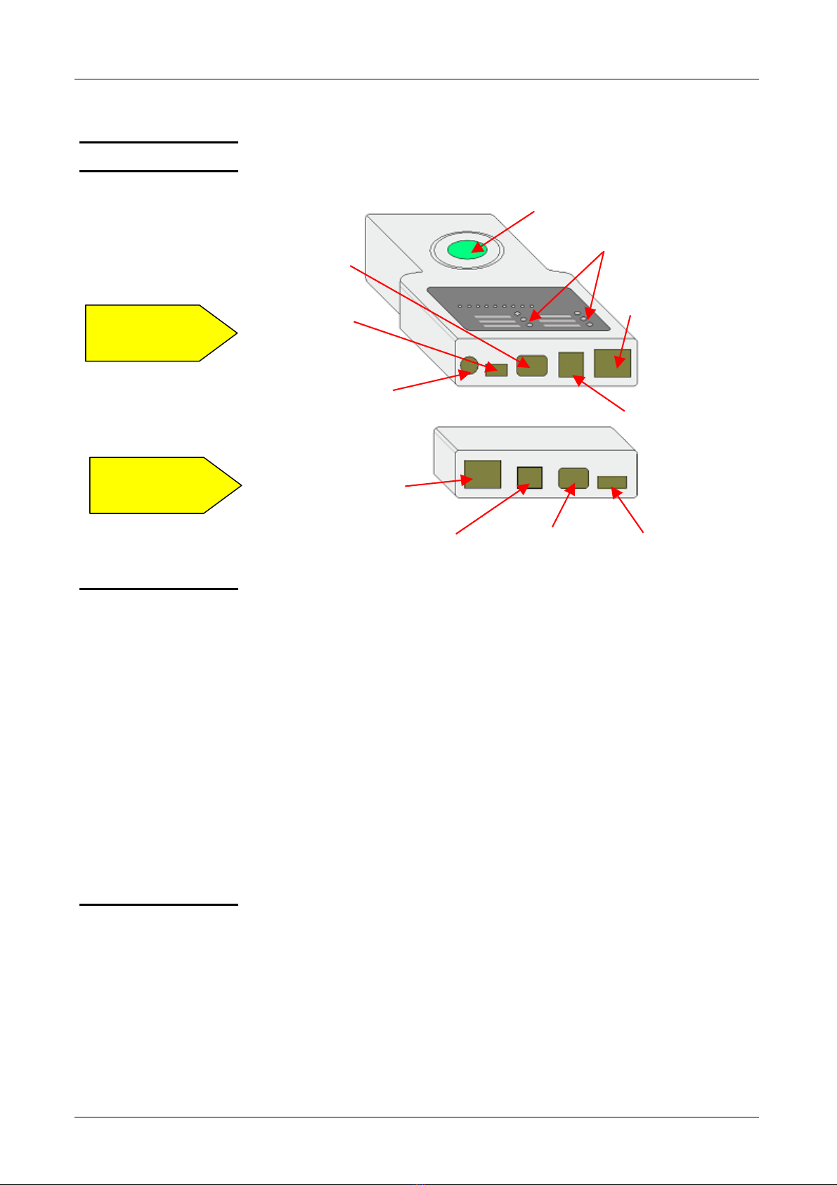
Legend for main
unit
1.
Test control push button (green)
2.
Test LEDs (see detailed drawing)
3.
RJ-45 connector for testing 10BASE-T LAN and INTERNET cables ,
EIA/TIA-568/568B, AT&T268A, Token Ring and all other cable systems
fitted with an RJ-45 connector.
4.
RJ-11 connector for testing telephone type cables, PhonNet and any
other cable system fitted with RJ-11 connectors.
5.
IEEE 1394 connector for testing cables fitted with IEEE connector 1394.
6.
USB B connector for testing USB link type cables and any other cable
system fitted with USB connectors.
7.
BNC Connector for testing 10BASE-2/10BASE-5 ETHERNET terminal
connection cables.
Legend for
secondary unit
8.
Connection for other end of RJ-45 connector
9.
Connection for other end of RJ-11 connector
10. Connection for other end of IEEE 1394 connector
11. Connection for other end of USB B connector
1. "Green" test
p
ush button
2. Test LEDs
3. Connector RJ-45
4. Connector RJ-11
10. Connector
IEEE 1394
6. Connector
USB B
7. Connector
BNC
8. RJ-45 Connector
9. RJ-11 Connector 10. IEEE 1394
Connector
11. USB B
Connector
MAIN
UNIT
SECONDARY
UNIT
English
12 CT 51
Test LEDs on main unit
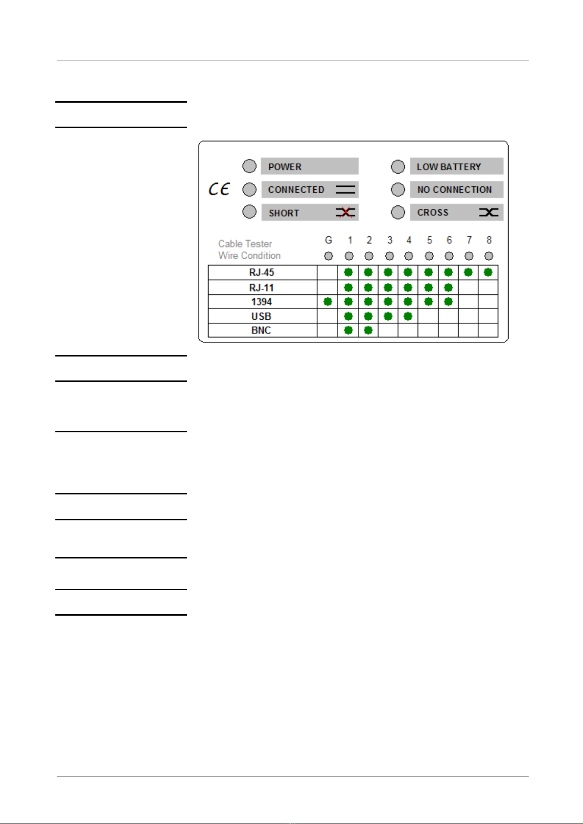
Indication of results by diodes (LEDs)
Detailed drawing
POWER Operating indicator
CONNECTED The blue LED goes ON when the connection between the two units is
established. In display G 1-8, the LEDs of the conducting conductors
go ON and an audio signal is activated.
SHORT The red LED goes ON when the connection is made between the
main unit and the secondary unit and the cable has a short-circuit. In
display G 1-8, the LEDs corresponding to the short-circuiting
conductors go ON and two audio signals are activated.
LOW BATTERY When the yellow LED goes ON, the 9 V battery needs replacing.
NO CONNECTION If the LED is ON, the secondary unit or the load resistance (BNC) is
not connected to the main unit.
CROSS The yellow LED goes ON to indicate that the links are crossed over in
the connecting cable between the main unit and the secondary unit.
Test activation Press the green button at the centre of the tester.
Reading results
1 Do not connect the tester to a powered cable.
2 Do not test more than one cable at a time.
3 On RJ-45 connectors, the test is performed on 8 LEDs, or on 9 LEDs
if the instrument is fitted with a ground connection.
4 As RJ-11 connectors have 6 wires, the result is read on 6 LEDs.
5 With a 1394 link, the result is read on 7 LEDs.
6 As USB connectors have 4 wires, the result is read on 4 LEDs.
7 The BNC connector is read on 2 LEDs.
English
CT 51 13
Test LEDs on main unit (continued)
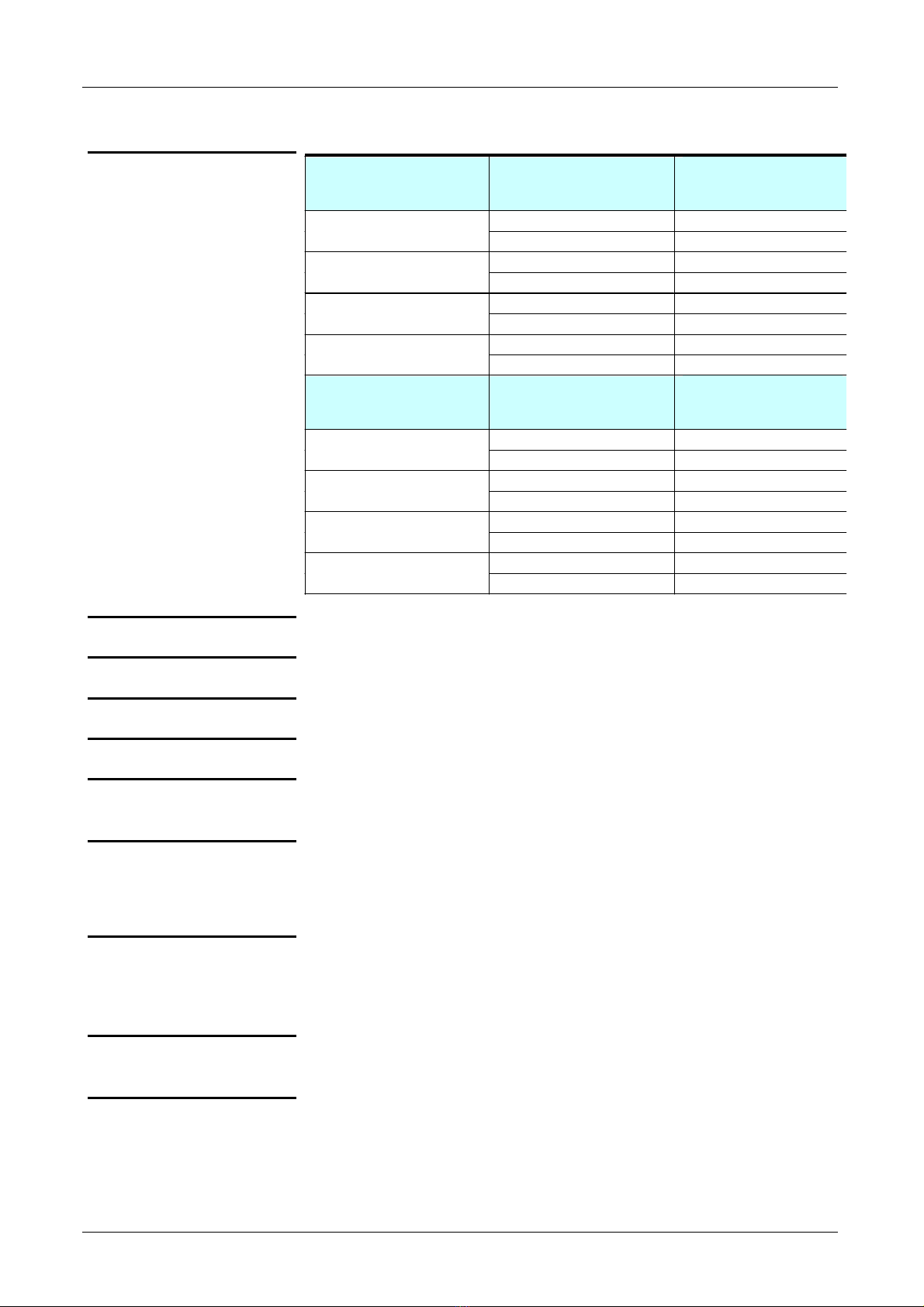
Connection diagram
and cable pair colours Pair identification Wire colour codes
T568A
Pin number on
connector
white/blue 5
Pair 1 blue 4
white/orange 3
Pair 2 orange 6
white/green 1
Pair 3 green 2
white/brown 7
Pair 4 brown 8
Pair identification Wire colour codes
T568B
Pin number on
connector
white/blue 5
Pair 1 blue 4
white/orange 1
Pair 2 orange 2
white/green 3
Pair 3 green 6
white/brown 7
Pair 4 brown 8
Protection Do not use on powered cable.
Power supply One 9 V battery (6 LF22)
Safety/Standard IEC/EN 61010-1 ; Cat. I ; 50 V ; Pol. 2
Maximum range For RJ11, RJ45 and BNC: approximately 180 m
General Specifications
Temperature
Operation -5°C to 45°C
Storage -10°C to 85°C
Mechanical
Dimensions 200 x 100 x 27 mm
Weight 280 g (cable and battery included)
Supply
delivered with the
instrument
Adaptors
Cables
One 9 V battery
One operating manual

Deutsch
14 CT 51
Allgemeine Hinweise
Vorbemerkung Wir beglückwünschen Sie zu Ihrem Kauf.
Dieses Gerät gehört zur Serie MULTIMETRIX.
Bitte lesen Sie vor Benutzung des Geräts die Sicherheitshinweise
und beachten Sie die Warnhinweise, um Verletzungsgefahren wie
z. B. Verbrennungen oder Stromschläge auszuschließen.
Sicherheit Verwenden Sie dieses Gerät ausschließlich für den vorgesehenen Zweck.
Sicheres Arbeiten • Verwenden Sie das Gerät nicht in elektrischen Schaltschränken.
• Halten Sie stets die angegebene maximal zulässige Spannung ein.
• Prüfen Sie die Gerätefunktion vor einer Benutzung.
• Benutzen Sie niemals ein beschädigtes Gerät.
• Fassen Sie das Gerät immer nur hinter dem Griffschutz an (falls vor-
handen).
• Benutzen Sie das Gerät niemals in feuchter oder staubiger Umgebung.
• Versuchen Sie nicht das Gehäuse zu öffnen.
• Lediglich das Batteriefach darf geöffnet werden (falls vorhanden).
• Benutzen Sie das Gerät niemals mit geöffnetem Batteriefach.
Garantie Dieses Gerät unterliegt einer Garantie gegen Werkstoff- und Herstellungs-
mängel entsprechend unseren allgemeinen Verkaufsbedingungen.
Während der Garantiefrist von 1 Jahr darf das Gerät nur vom Hersteller
repariert werden, wobei sich dieser das Recht vorbehält, das Gerät
instand zu setzen oder es ganz oder teilweise auszutauschen.
Die Kosten für die Rücksendung des Geräts zum Hersteller gehen zu
Lasten des Käufers.

Deutsch
CT 51 15
Allgemeine Hinweise (Fortsetzung)
Garantie
(Fortsetzung)
Die Garantieleistung ist in folgenden Fällen ausgeschlossen:
1. Bei unsachgemäßer Verwendung des Geräts oder seiner
Verwendung in Verbindung mit unkompatiblen anderen Geräten.
2. Bei Eingriffen oder Änderungen am Gerät, die ohne ausdrückliche
Zustimmung des Herstellers vorgenommen wurden.
3. Bei Eingriffen am Gerät, die von Personen vorgenommen wurden, die
vom Hersteller dazu nicht ausdrücklich befugt sind.
4. Bei Anpassungen des Geräts an Anwendungen, für die es laut
Definition oder Hinweisen in der Bedienungsanleitung nicht
vorgesehen ist.
5. Bei Schäden durch Schlag-, Stoß-, Sturz- oder Wassereinwirkung.
Verpackung Das vollständige Gerät wurde vor dem Versand mechanisch und
elektrisch geprüft.
Bei Erhalt des Geräts empfiehlt es sich, es sofort auf eventuelle
Transportschäden zu prüfen. Melden Sie die Transportschäden
unverzüglich dem Zusteller bzw. Spediteur und nehmen Sie die
Lieferung nur unter Vorbehalt an.
Verwenden Sie für die Rücksendung des Geräts immer die Originalver-
packung und legen Sie eine Notiz mit dem Grund für die Rücksendung
bei.
Wartung
Messtechnische
Überprüfung
Wie bei jedem Mess- oder Prüfgerät ist eine regelmäßige Überprüfung
bzw. Nachkalibrierung notwendig. Wenden Sie sich hierzu bitte an die für
Ihre Region zuständige Chauvin-Arnoux-Niederlassung.
Reinigung • Reinigen Sie Ihren Prüfer regelmäßig mit einem leicht mit
Seifenlauge angefeuchteten, weichen Tuch.
• Verwenden Sie dazu niemals Scheuermittel oder
lösungsmittelhaltige Reiniger.
Batterie Zum Auswechseln der Batterie drücken Sie auf den Deckel des
Batteriefachs auf der Geräterückseite und schieben Sie ihn nach rechts.
Achten Sie beim Einlegen der Batterie auf die richtige Polarität.
Bewahren Sie die Batterie stets außerhalb der Reichweite von Kindern
auf.
Aufbewahrung Wenn Sie Ihren Prüfer für längere Zeit nicht benutzen (2 Monate oder
mehr) sollten Sie die Batterie herausnehmen und separat lagern.

Deutsch
16 CT 51
Beschreibung des Geräts
Gerätebenutzung
Bedienung 1. Schließen Sie an einem Ende des zu prüfenden Kabels die Remote-
Einheit an und den Kabeltester am anderen Ende.
Bei bereits verlegten Kabeln können Sie die Remote-Einheit durch
seitliches Verschieben vom Kabeltester trennen und in einem andern
Raum anschließen.
2. Drücken Sie auf die grüne Test-Taste in der Mitte des Geräts.
3. Lesen Sie das Ergebnis an den Kontroll-LEDs auf dem Kabeltester ab
(siehe Kontroll-LEDs am Hauptgerät weiter unten).
Hinweis: An RJ-45 Steckern umfasst der Test 8 LEDs bzw. 9 LEDs,
wenn eine Masseverbindung vorhanden ist.
RJ-11 Stecker besitzen 6 Adern, der Test umfasst daher 6 LEDs.
Bei einer IEEE 1394 Verbindung umfasst der Test 7 LEDs.
USB Stecker besitzen 4 Adern und eine Masseverbindung, der Test
umfasst daher 5 LEDs.
Der Test einer BNC-Verbindung umfasst 2 LEDs.
Frontseite
Abbildung
1 - Test-Taste
2 - Anzeigefeld mit
Leuchtdioden
8 - RJ-45
9 - RJ-11 10 - IEEE 1394 11 - USB A
7 - BNC
6 - USB B 4 - RJ-11
5 - IEEE 1394
3 - RJ-45
Kabeltester
Remote-Einheit

Deutsch
CT 51 17
Beschreibung des Geräts (Fortsetzung)
Teilebezeichnungen
am Kabeltester
1.
Grüne Test-Taste
2.
Kontroll-LEDs (siehe Einzelheiten auf nächster Seite)
3.
Steckkontakt RJ-45 zum Testen von LAN- und INTERNET 10BASE-T
Kabeln, EIA/TIA-568/568B, AT&T268A, Token Ring sowie anderer
Verkabelungs-systeme mit RJ-45 Steckkontakten
4.
Steckkontakt RJ-11 zum Testen von Telefon- und PhonNet-Kabeln sowie
anderer Verkabelungssysteme mit RJ-11 Steckkontakten
5.
Steckkontakt IEEE 1394 zum Testen von Kabeln mit IEEE 1394
Steckern.
6.
Steckkontakt USB B zum Testen von USB-Verbindungskabeln sowie
anderer Verkabelungssysteme mit USB-Steckern.
7.
Steckkontakt BNC zum Testen von Terminal-Verbindungskabeln
ETHERNET 10BASE-2/10BASE-5.
Teilebezeichnungen
an der Remote-
Einheit
8.
Steckkontakt für anderes Ende der RJ-45 Verkabelung
9.
Steckkontakt für anderes Ende der RJ-11 Verkabelung
10.
Steckkontakt für anderes Ende der IEEE 1394 Verkabelung
11.
Steckkontakt für anderes Ende der USB A Verkabelung

Deutsch
18 CT 51
Kontroll-LEDs am Kabeltester
Anzeigefeld
Testergebnisanzeige durch Leuchtdioden (LEDs)
POWER Betriebsanzeige
CONNECTED
Diese blaue LED leuchtet, wenn Kabeltester und Remote-Einheit
angeschlossen sind. Im LED-Feld darunter leuchten die entsprechen-
den Dioden G (Masse) und 1 bis 8 auf und ein Piepston ertönt.
SHORT
Diese rote LED leuchtet, wenn Kabeltester und Remote-Einheit
angeschlossen sind und das Kabel einen Kurzschluss aufweist.
Im LED-Feld darunter leuchten die LEDs der jeweils kurzgeschlossenen
L
auf und es ertönen 2 Signaltöne.
LOW BATTERY Wenn diese gelbe LED leuchtet, muss die 9 V-Batterie ersetzt werden.
NO CONNECTION
Diese LED leuchtet, wenn die Remote-Einheit die Verbindung nicht
richtig überbrückt oder die BNC-Verbindung nicht durch den Last-
widerstand abgeschlossen ist.
CROSS Diese gelbe LED leuchtet, wenn die Kabelverbindung zwischen
Kabeltester und Remote-Einheit überkreuz verläuft.
Starten des Tests Drücken Sie dazu die grüne Test-Taste in der Mitte des Testers und
beobachten Sie die LEDs in der Anzeige um Fehler festzustellen.

Deutsch
CT 51 19
Kontroll-LEDs am Kabeltester (Fortsetzung)
Anschlussbelegung und
Farbcode der Adern
Kennzeichnung der Paare Farbcode der Adern T568A
Pin-Nr. des Steckers
weiß/blau 5
Paar 1 blau 4
weiß/orange 3
Paar 2 orange 6
weiß/grün 1
Paar 3 grün 2
weiß/braun 7
Paar 4 braun 8
Kennzeichnung der Paare Farbcode der Adern T568B
Pin-Nr. des Steckers
weiß/blau 5
Paar 1 blau 4
weiß/orange 1
Paar 2 orange 2
weiß/grün 3
Paar 3 grün 6
weiß/braun 7
Paar 4 braun 8
Technische Daten
Stromversorgung 1 x 9 V- Batterie (6LF22)
Sicherheit/Norm gemäß IEC/EN 61010-1 - Cat. I 50 V - Verschmutzungsgrad 2
Reichweite Bei RJ11-, RJ45- und BNC-Kabelverbindungen ca. 180 m
Temperatur Betrieb: - 5°C bis +45°C
Lagerung: -10°C bis +85°C
Abmessungen 200 x 100 x 27 mm
Gewicht 280 g (einschl. Kabel und Batterie)
Lieferumfang
Serienmäßig geliefert Adapter (RJ11, R45 und BNC-Steckverbinder mit Lastwiderstand)
Tasche
9 V-Batterie
Bedienungsanleitung
Italiano
20 CT 51
Istruzioni generali
Introduzione Complimenti per l'acquisto.
Il presente strumento fa parte della gamma MULTIMETRIX.
Leggi le seguenti istruzioni di sicurezza prima di utilizzarlo e fai riferimento
ai messaggi di sicurezza, per evitare eventuali incidenti corporei quali le
bruciature e gli shock elettrici.
Simbolo E' imperativo seguire le indicazioni precedute dal simbolo .
Sicurezza Utilizza il presente apparecchio unicamente nell'ambito della sua
applicazione.
Per lavorare in totale
sicurezza ....
• Non utilizzarlo negli armadi elettrici.
• Non lavorare mai al di là delle fascie di tensione max. indicate.
• Verifica lo stato di funzionamento dell'apparecchio prima
dell'utilizzazione.
• Non utilizzare l'apparecchio, se è danneggiato.
• Non utilizzare mai questo strumento in ambiente umido o polveroso.
• Non smontare la scatola.
• Solo il portello d'accesso alle pile puo' essere aperto
• Non utilizzare mai lo strumento, con il portello d'accesso alle pile
aperto.
Garanzia Il presente materiale è garantito contro qualsiasi eventuale difetto di
materiale o vizio di fabbricazione, conformemente alle condizioni generali
di vendita.
Durante il periodo di garanzia (1 anno), lo strumento può essere riparato
solo dal costruttore, e questi si riserva la decisione di procedere alla
riparazione o alla permuta dell’apparecchio, o di una sua parte.
In caso di ritorno del materiale al costruttore, il costo della spedizione
d'andata è a carico del cliente.
Table of contents
Languages:
Other Multimetrix Test Equipment manuals

Multimetrix
Multimetrix VT 35 User manual

Multimetrix
Multimetrix MH 401 User manual

Multimetrix
Multimetrix EIIT 810 User manual

Multimetrix
Multimetrix ERT 200 Instruction Manual

Multimetrix
Multimetrix VT 35 User manual

Multimetrix
Multimetrix RCD 501 User manual

Multimetrix
Multimetrix ERT 201 User manual

Multimetrix
Multimetrix XG 2102 User manual


