manuals.online logo
Brands
  1. Home
  2. •
  3. Brands
  4. •
  5. MULTISPAN
  6. •
  7. Measuring Instrument
  8. •
  9. MULTISPAN PIC-4202 User manual

MULTISPAN PIC-4202 User manual

PIC-4202
PROCESS INDICATOR
TECHNICAL SPECIFICATION
ENVIRONMENT CONDITION:
Relative Humidity
Protection Level
(As per request)
Operating Temp. 0°C to 55°C
UP to 95% RH
(non-condensing)
IP-65 (Front side) As per IS/IEC
60529 : 2001
TERMINAL CONNECTION
MECHANICAL INSTALLATION
Page -1
INPUT SPECIFICATION
Input Types
I/P Filter Time
Indication
Accuracy
Resolution
Range
±1% FSD ± 1 digit
(FSD - Full Scale Deflection)
Decimal point selectable:
-999 to 9999 (For all I/P)
0.1, 0.01, 0.001, 0001
DISPLAY AND KEY
DIMENSION:
Display
Size
Keys
Panel Cutout
4 digit, 7 seg, 0.56” RED
4 digit, 7 seg, 0.33” GREEN
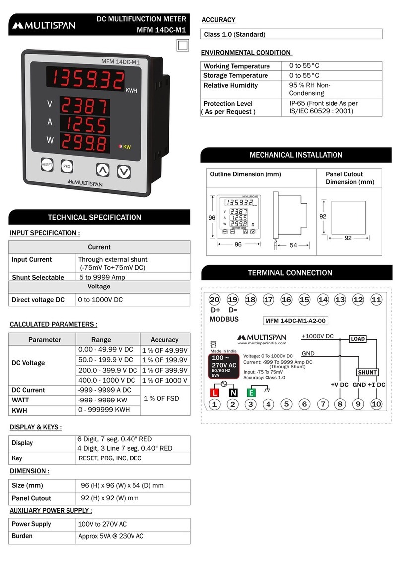
48 (H) x 48 (W) x 95 (D) mm
SET,INC,DEC,ENT
45 (H) x 45 (W) mm
POWER SUPPLY
Power
Consuption
(VA Rating)
Supply
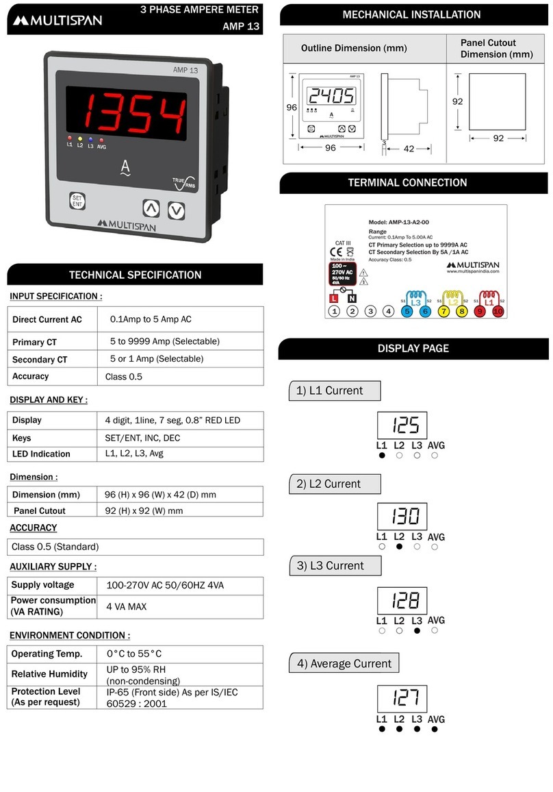
Voltage 100 to 270V AC, 50-60Hz
4VA @ 230V AC MAX
UPPER:
LOWER:
Voltage:
Current:
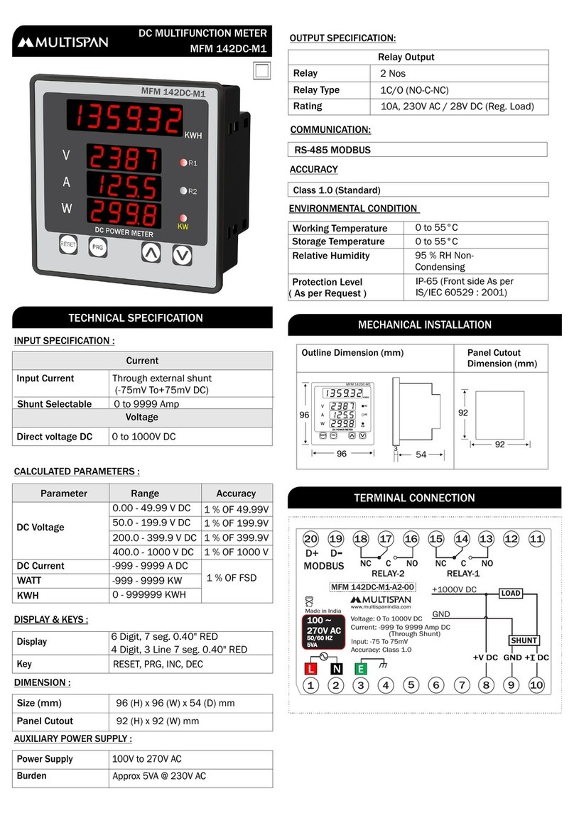
0 to 10V DC
0 to 20mA DC,
4 to 20mA DC
0.1 Sec to 10 Sec
Panel Cutout
Dimension (mm)
Outline Dimension(mm)
48
95
45
45
3
48 R1
R2
SET ENT
PIC 4202
SV
PV
I/P
0/4 To 20
mA DC
I/P
0 To 10V DC
++
-
NC
C
R1
NO
C
NO
R2
1
2
3
4
5
6
7
8
9
10
www.multispanindia.com
!
100
270V AC
50/60 Hz
4VA
L
N
~
Made in India
6
8
7
7
(0-10V DC)
(4-20mA DC or
0-20mA DC)
+
+
Connection for voltage I/P
Connection for current I/P
!
1. Prepare the panel cutout with proper dimensions as show
above.
2. Fit the unit into the panel with the help of clamp given.
3.The equipment in its installed state must not come in close
proximity to any heating source, caustic vapors, oils steam,
or other unwanted process by products.
4. Use the specified size of crimp terminal (M3.5 screws) to
wire the terminal block. Tightening the screws on the
terminal block using the tightening torque of the range of
1.2 N.m.
5. Do not connect anything to unused terminals.
1. This equipment, being built-in-type, normally becomes a
part of main control panel and in such case the terminals
do not remain accessible to the end user after installation
and internal wiring.
2. Do not allow pieces of metal, wire clippings, or fine
metallic fillings from installation to enter the product or
else it may lead to a safety hazard that may in turn
endanger life or cause electrical shock to the operator.
3. Circuit breaker or mains switch must be installed
between power source and supply terminal to facilitate
power ‘ON’ or ‘OFF’ function. However this mains switch
or circuit breaker must be installed at convenient place
normally accessible to the operator.
4. Use and store the instrument within the specified ambient
temperature and humidity ranges as mentioned in this
manual.
INSTALLATION GUIDELINES
MECHANICAL INSTALLATION GUIDELINES
1. The equipment should be cleaned regularly to avoid
blockage of ventilating parts.
2. Clean the equipment with a clean soft cloth. Do not use
isopropyl alcohol or any other cleaning agent.
3. Fusible resistor must not be replaced by operator.
Read complete instructions prior to installation
and operation of the unit.
WARNING : Risk of electric shock.
All safety related codifications, symbols and instructions
that appear in this operating manual or on the equipment
must be strictly followed to ensure the safety of the operating
personnel as well as the instrument.
If all the equipment is not handled in a manner specified
by the manufacturer, it might impair the protection provided
by the equipment.
WARNING : Risk of electric shock.
1. To prevent the risk of electric shock power supply to the
equipment must be kept OFF while doing the wiring
arrangement. Do not touch the terminals while power is
being supplied.
2. To reduce electro magnetic interference, use wire with
adequate rating and twists of the same of equal size shall
be made with shortest connection.
MAINTENANCE
SAFETY PRECAUTION
WARNING GUIDELINES
3. Cable used for connection to power source, must have a
cross section of 1mm or greater. These wires should have
insulations capacity made of at least 1.5kV.
4. A better anti-noise effect can be expected by using
standard power supply cable for the instrument.
ERROR DISPLAY
When an error has occurred the display indicates error codes
as given below.
ERROR
OUER
LO
MEANING
Over range Input applied
1) For 0 to 10V DC - exceed
10 V DC
2) For 0/4-20mA dc - exceed
20mA DC
v
Page -2
FRONT PANEL DESCRIPTION
To edit parameter value & set
parameters value.
To increment the selected
parameter value.
To decrement the selected
parameter value.
For set parameter to be save.
SYMBOLFUNCTION
When I/P is 4 to 20mA DC
is selected, than I/P signal is
lower than SLL (0-5mA)
USER CONFIGURATION
Process Value
Set Value
Press key
SET
1234
2000
set1
2000
set2
1000
pass
Hys1
Hys2
mOD1
0123
0001
0001
L-AL
mOD2
INPT
DP
H-AL
4-20
0000
Set 1
Set 2
Password
Hysterisis-1
Hysterisis-2
Mode-1
Mode-2
Input
(4-20 mA , 0-20 mA ,0-10 VDC)
Decimal Point
(9999, 999.9 ,99.99,9.999)
(1 to 999)
(1 to 999)
(High Alarm,Low Alarm,Inband,
Outband,Absolute low,Absolut Out)
(High Alarm,Low Alarm,Inband,
Outband,Absolute low,Absolut Out)
Enter Password 123
To be continued
Press key
SET
Press key
SET
Press key
SET
Press key
SET
Press key
SET
Press key
SET
Press key
SET
Press key
SET
LRNg
HRNg
0000
2000
FLTR
O.5
OFST
CRFC
SLL
0000
0000
0000
Press key
SET
Press key
SET
Press key
SET
Press key
SET
Press key
SET
Press key
SET
Low Range
(-999 to 9999)
High Range
(-999 to 9999)
Filter Time
(0.1 to 10.0 Sec)
Off Set
(-999 to 999 Count)
Correction Factor
(-999 to 999 Count)
Signal Low Level
(Ampere Range : 0 to 5mA)
If input 4 to 20mA is seleced
Press key
SET
Press key to save & exit
ENT
Page -3
ABSOLUTE LOW ALARM
ABSOLUTE OUTBAND ALARM
RLY-OFF
RLY-OFF
RLY-ON
RLY-ON
RLY-ON
RLY-OFF
RLY-ON
RLY-ON
RLY-OFF
RLY-ON
RLY-OFF
RLY-OFF
RLY-OFF
RLY-OFF
SET
SET
SET
HYST
HYST
HYST
LOW ALARM:
HIGH ALARM:
INBAND ALARM
OUTBAND ALARM
RLY-OFF
RLY-ON RLY-ON
RLY-ON RLY-ON
RLY-ON
RLY-ON
RLY-ON
RLY-ON
RLY-ON
RLY-OFF
RLY-ON
RLY-ON
RLY-ON
RLY-ON
RLY-OFF
RLY-OFF
RLY-OFF
RLY-OFF
RLY-OFF
RLY-OFF
HYST
S.V
S.V
S.V
S.V
HYST
HYST
HYST
ALARM OPERATION
Page -4

Other MULTISPAN Measuring Instrument manuals

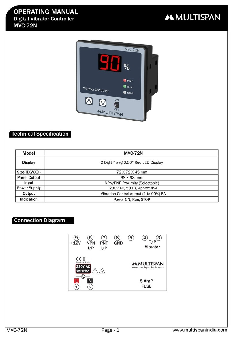
MULTISPAN MVC-72N User manual

MULTISPAN

MULTISPAN MVC-72N User manual

MULTISPAN RPM-1201 User manual

MULTISPAN

MULTISPAN RPM-1201 User manual

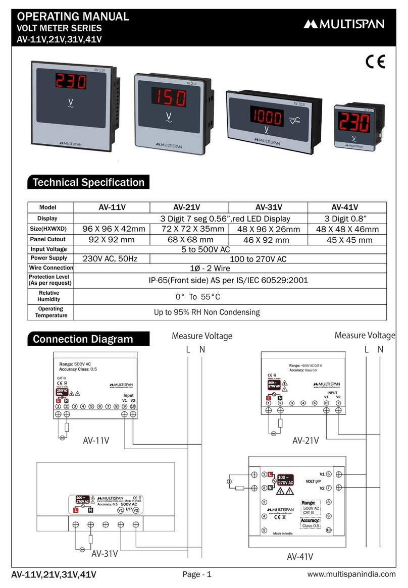
MULTISPAN AV-11A User manual

MULTISPAN

MULTISPAN AV-11A User manual

MULTISPAN AV-14DA User manual

MULTISPAN

MULTISPAN AV-14DA User manual

MULTISPAN MFM 142DC-M1 User manual

MULTISPAN

MULTISPAN MFM 142DC-M1 User manual

MULTISPAN MS-1208A User manual

MULTISPAN

MULTISPAN MS-1208A User manual

MULTISPAN EM-10 User manual

MULTISPAN

MULTISPAN EM-10 User manual

MULTISPAN PIC-38 User manual

MULTISPAN

MULTISPAN PIC-38 User manual

MULTISPAN AVH-14N User manual

MULTISPAN

MULTISPAN AVH-14N User manual

MULTISPAN DSM-14N User manual

MULTISPAN

MULTISPAN DSM-14N User manual

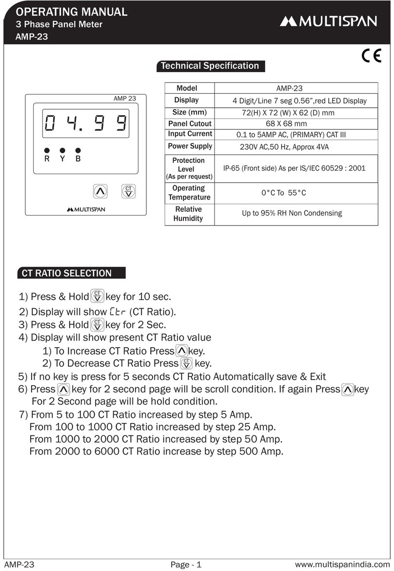
MULTISPAN AMP-23 User manual

MULTISPAN

MULTISPAN AMP-23 User manual

MULTISPAN MFM 14DC User manual

MULTISPAN

MULTISPAN MFM 14DC User manual

MULTISPAN AV-41CT User manual

MULTISPAN

MULTISPAN AV-41CT User manual

MULTISPAN MI-631P User manual

MULTISPAN

MULTISPAN MI-631P User manual

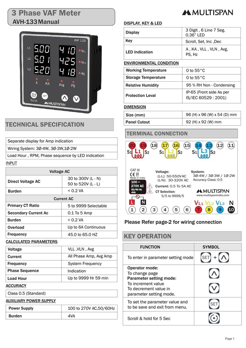
MULTISPAN AVH-133 Manual User manual

MULTISPAN

MULTISPAN AVH-133 Manual User manual

MULTISPAN MFM-13 User manual

MULTISPAN

MULTISPAN MFM-13 User manual

MULTISPAN AVH 14N-M1 User manual

MULTISPAN

MULTISPAN AVH 14N-M1 User manual

MULTISPAN AVF-19N User manual

MULTISPAN

MULTISPAN AVF-19N User manual

MULTISPAN MFM 14DC-M1 User manual

MULTISPAN

MULTISPAN MFM 14DC-M1 User manual

MULTISPAN VOLT-19N User manual

MULTISPAN

MULTISPAN VOLT-19N User manual

MULTISPAN AVH-14N User manual

MULTISPAN

MULTISPAN AVH-14N User manual

MULTISPAN AMP 13 User manual

MULTISPAN

MULTISPAN AMP 13 User manual

MULTISPAN MFM13 User manual

MULTISPAN

MULTISPAN MFM13 User manual

MULTISPAN MFM 13-M1 User manual

MULTISPAN

MULTISPAN MFM 13-M1 User manual

Popular Measuring Instrument manuals by other brands

Knick Stratos Pro A2 COND Series quick start guide

Knick

Knick Stratos Pro A2 COND Series quick start guide

AEMC 6250 user manual

AEMC

AEMC 6250 user manual

Deta-Elis DeVita Professional instruction manual

Deta-Elis

Deta-Elis DeVita Professional instruction manual

Brainstorm Electronics DCD-8 Operation manual

Brainstorm Electronics

Brainstorm Electronics DCD-8 Operation manual

Klemsan ECRAS 100-VCF instruction manual

Klemsan

Klemsan ECRAS 100-VCF instruction manual

AEM 30-5133 manual

AEM

AEM 30-5133 manual

LIMIT L40 user manual

LIMIT

LIMIT L40 user manual

Lovibond Photometer-System MD100 instruction manual

Lovibond

Lovibond Photometer-System MD100 instruction manual

Omnicomm LLD user manual

Omnicomm

Omnicomm LLD user manual

Extech Instruments 380193 user guide

Extech Instruments

Extech Instruments 380193 user guide

Agilent Technologies 6811B user guide

Agilent Technologies

Agilent Technologies 6811B user guide

Swatchmate Cube user guide

Swatchmate

Swatchmate Cube user guide

Red Ion PAXLR000 quick start guide

Red Ion

Red Ion PAXLR000 quick start guide

Graytechnos photom MINI 364 instruction manual

Graytechnos

Graytechnos photom MINI 364 instruction manual

Hanna Instruments edge pH manual

Hanna Instruments

Hanna Instruments edge pH manual

MR MSENSE DGA 2 operating instructions

MR

MR MSENSE DGA 2 operating instructions

Extech Instruments MO220 user manual

Extech Instruments

Extech Instruments MO220 user manual

LaserLiner SuperCross SCL 2 operating instructions

LaserLiner

LaserLiner SuperCross SCL 2 operating instructions

manuals.online logo
manuals.online logoBrands
  • About & Mission
  • Contact us
  • Privacy Policy
  • Terms and Conditions

Copyright 2025 Manuals.Online. All Rights Reserved.