MUNBYN IMC01 User manual

User Manual
IMC01 Banknote Counter
1.06

Page2of41
IMC01 Banknote Counter User Manual
Version 1.06
Contents
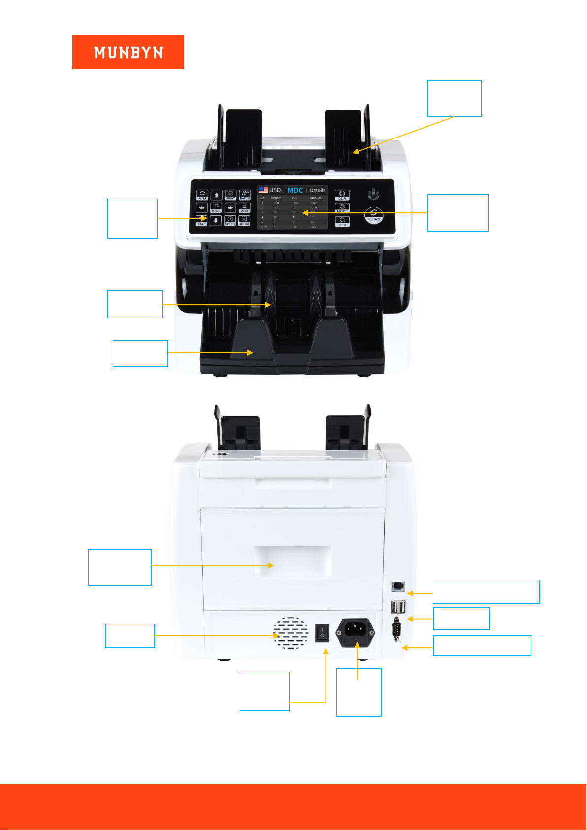
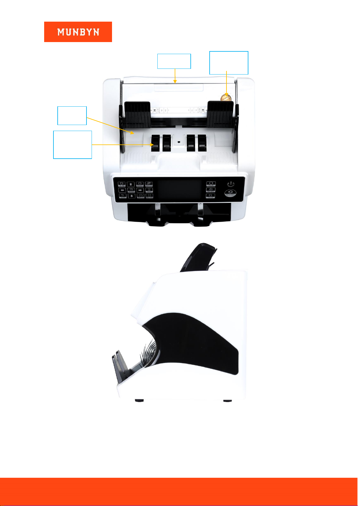
1.0. Machine Overview .....................................................................................................4
2.0. Packing Open and Installation....................................................................................6
2.1. Packing List......................................................................................................................6
2.2. Installation and Use Location............................................................................................6
2.3. Installation Instructions......................................................................................................7
2.3.1. Installation Warnings ................................................................................................7
2.3.2. Power Supply Connection.........................................................................................8
2.3.3. Banknote Guider Installation.....................................................................................8
3.0. Display and Operation Interface.................................................................................9
3.1. Display Appearance..........................................................................................................9
3.2. Operational Instructions for Function Keys........................................................................9
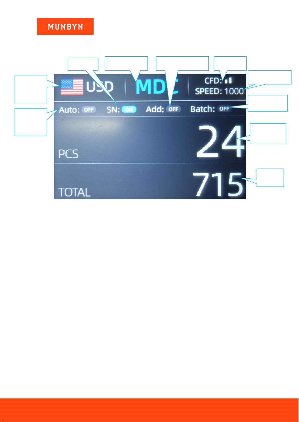
3.3. Display Interface.............................................................................................................10
4.0. Operating Instructions .............................................................................................11
4.1. Start-up...........................................................................................................................11
4.2. Selection of Counting Mode............................................................................................11
4.2.1. Single Currency Counting Mode .............................................................................11
4.2.2. Automatic Recognition Mode..................................................................................13
4.2.3. Multi-currency Counting Mode................................................................................15
4.2.4. Non-Volatile Memory for Currency Mode ................................................................16
4.3. Counting Function Options..............................................................................................16
4.3.1. Automatic Banknote Counting.................................................................................16
4.3.2. SN Reading............................................................................................................16
4.3.3. Batch Setting..........................................................................................................16
4.3.4. Accumulation..........................................................................................................17
4.4. Counting Speed Setting..................................................................................................18
4.5. Check Detail of Counting ................................................................................................18
4.5.1. Check the Serial Number........................................................................................18
4.6. Print Information .............................................................................................................19
4.7. CFD Level ......................................................................................................................19
5.0. Menu Setting............................................................................................................21
5.1. Service Menu..................................................................................................................21
5.1.1. Read Sensor Values...............................................................................................22
5.1.2. CIS Calibration.......................................................................................................22
5.1.3. MG/MT Waveforms ................................................................................................23
5.1.4. Password Setting....................................................................................................23
5.1.5. Auto Diagnostic......................................................................................................23
5.1.6. PCS Counted and Reset.........................................................................................23
5.1.7. Acquire CIS image..................................................................................................24
5.1.8. Detection Level.......................................................................................................24
5.1.9. IP Address..............................................................................................................25
5.1.10. Back to Default setting............................................................................................25
5.2. Version Information.........................................................................................................25
5.3. Time Setting ...................................................................................................................26
5.4. Language Selection ........................................................................................................26
6.0. Software Upgrade ....................................................................................................27
7.0. Maintenance ............................................................................................................29
7.1. Cleaning the Machine .....................................................................................................29
7.1.1. Clean the Hopper ...................................................................................................29
7.1.2. Clean the Stacker Sensors.....................................................................................30
7.1.3. Clean the Internal Sensors .....................................................................................31
7.2. Error Code......................................................................................................................32

Page3of41
IMC01 Banknote Counter User Manual
Version 1.06
7.3. Bill Jam...........................................................................................................................32
7.4. Feeding Gap Calibration.................................................................................................33
7.5. CIS Calibration................................................................................................................36
7.6. Back to Default Setting....................................................................................................38
7.7. Sensor Errors .................................................................................................................39
7.7.1. Hopper Sensor Error...............................................................................................39
7.7.2. Stacker Sensor Error..............................................................................................39
7.7.3. Counting Sensor Error............................................................................................39
8.0. Technical Parameters...............................................................................................40

Page4of41
IMC01 Banknote Counter User Manual
Version 1.06
1.0. Machine Overview
Figure 1-1 IMC01 Front Diagram
Figure 1-2 IMC01 Back Diagram
Banknote
Guider
Touch
Panel
TFT LCD
Display
Stacker
Impeller
Handle of
Back Cover
Speaker
Switch
On/Off
Power
Cord
Jack
RS232 Printer Port
External Display Port
USB Port

Page5of41
IMC01 Banknote Counter User Manual
Version 1.06
Figure 1-3 IMC01 Top Diagram
Figure 1-4 IMC01 Side Diagram
Handle
Adjustable
Screw
Banknote
Processing
Wheel
Hopper

Page6of41
IMC01 Banknote Counter User Manual
Version 1.06
2.0. Packing Open and Installation
2.1. Packing List
When you receive the package, open and check the packing list in the package.
Table 2-1 Packing List
Item Name
Picture
Quantity (pcs)
Description
Banknote Counter
1
Mixed denomination Banknote counter
External Display
1
External LED display screen with RJ12 cable
Power Cable
1
Power supply cable of American standard
1
Power supply cable of European standard
1
Power supply cable of United Kingdom’s
standard
Banknote Guiders
2
Install at the hopper
CIS Calibration
Paper
1
Used for the CIS calibration
Nylon Brush
1
Clean the machine
Soft cleaning Cloth
1
Clean the CIS or the other sensors
Fuse
1
The backup fuse for the power protection
User Manual
1
2.2. Installation and Use Location
As shown in figure 2-1, please stay away from the surrounding walls and reserve sufficient operation space for
placement of banknotes, opening or closing of the cover plate, as well as for maintenance.

Page7of41
IMC01 Banknote Counter User Manual
Version 1.06
40 40
350
160
405
288
350
405
510
Figure 2-1 Installation and use location
2.3. Installation Instructions
2.3.1. Installation Warnings
1) This machine is specially designed for indoor use. Please do not install or use it outdoors.
2) Please do not install it in place that cannot bear the weight of this product or in places that are inclined or
uneven.
3) Do not use or please combustible materials, inflammables and volatile items such as thinners around/inside
this product.
Maintenance Space
Installation Space

Page8of41
IMC01 Banknote Counter User Manual
Version 1.06
2.3.2. Power Supply Connection
Figure 2-2 Power and External Display Connection
2.3.3. Banknote Guider Installation
Figure 2-3 Banknote Guider
External Display
Connector
Power Cord
Connector
Power Supply

Page9of41
IMC01 Banknote Counter User Manual
Version 1.06
3.0. Display and Operation Interface
3.1. Display Appearance
Figure 3-1 Display Appearance
3.2. Operational Instructions for Function Keys
Auto on key, to switch on/off the automatic operation. Auto: automatically counting as long as there is
banknote on the hopper. Manual: manually counting by press the restart key.
Direction keys.
Print key, to print the counted banknotes information.
Batch key, to select the batch number.
Menu key, to enter the menu interface by long pressing the key until a beep sound.
Add key, to switch on/off the accumulation function.
Return key, to return to the previous interface.
Speed key, to select the different available counting speeds.
Detail key, to check the detail counted information.
Currency key, to select the one of currency, auto recognition or multi-currency mode for counting.
Mode key, to select CNT mode, SDC mode or MDC mode for counting.
CFD level key, to select the Counterfeit Detection Sensitivity level.
Restart key, to start counting, or to start other operations.
Power key, long press to enter the standby mode, or press to resume to the working mode
Operational Keys
Display Area
Operational Keys

Page10of41
IMC01 Banknote Counter User Manual
Version 1.06
3.3. Display Interface
Figure 3-2 Main Display Interface
Currently
selected
currency
Counting mode
Accumulation status
CFD level
Counted
amount
Number of
banknotes
Counting speed
Batch Number
SN option
Auto
detecting
status

Page11of41
IMC01 Banknote Counter User Manual
Version 1.06
4.0. Operating Instructions
4.1. Start-up
Turn on the switch after connecting the machine to power supply. First, the machine enters the self-checking
interface, as shown in Figure 4-1.
Figure 4-1 Self-checking Interface
Please wait patiently for about 20 seconds, and the machine will spin the banknote processing wheel several
times to conduct a self-check, and then enter the main interface as shown in Figure 4-2.
Figure 4-2 Counting Ready State Interface
4.2. Selection of Counting Mode
4.2.1. Single Currency Counting Mode
After the machine is turned on, the flag & currency graphic appears in the upper left corner, indicating that the
machine is in the current currency counting mode.
The default mode is MDC mode. By pressing the key of the control panel, three counting modes can be
cyclically switched, and the 3 counting modes will be cyclically switched according to MDC-CNT-SDC
sequence.
4.2.1.1. MDC Mode
As shown in Figure 4-3, the IMC01 is in MDC mode. In this mode, the IMC01 will count the banknotes of all
denominations of the selected currency, and save the detail information of the counted banknotes at the same
time, including the total amount and the total number of the banknotes in stacker, so as to facilitate users to
check. In this mode, the IMC01 has 2 counting speed (800/1000 pcs/min) options.

Page12of41
IMC01 Banknote Counter User Manual
Version 1.06
Figure 4-3 Initial Interface of MDC Mode
Figure 4-4 Interface after MDC Counting
4.2.1.2. SDC Mode
As shown in Figure 4-5, the IMC01 is in SDC mode. In this mode, the IMC01 will count the banknotes of the
same denomination of the selected currency with the first banknote counted as a reference, and save the detail
information of the counted banknotes at the same time, including the total amount and the total number of the
banknotes in stacker, so as to facilitate users to check. In this mode, the IMC01 has 2 counting speed
(800/1000/min) options.

Page13of41
IMC01 Banknote Counter User Manual
Version 1.06
Figure 4-5 Initial Interface of SDC Mode
Figure 4-6 Interface after SDC Counting
You can use this function to sort the mixed bill manually.
4.2.1.3. CNT Mode
As shown in Figure 4-7, the IMC01 is in CNT mode. This mode does not limit the currency, and only count the
number of banknotes. It only works with double note detection function and no other counterfeit detection
function. In this mode, the IMC01 has 4 counting speed (800/1000/1200/1500 pcs/min) options.
Figure 4-7 Initial Interface of CNT Mode
Figure 4-8 Interface after CNT Counting
Note: In the MDC and SDC mode, the IMC has the functions of image acquisition, magnetic detection,
ultraviolet detection and double note detection. While in the CNT mode, there is only a double note detection
function.
4.2.2. Automatic Recognition Mode
In the process of counting banknotes, the IMC01 uses the first banknote passing through the sensor as the
judgment rule to recognize the banknotes of all denominations of the same currency. When banknotes of other
currencies are recognized, the machine will alarm and stop. At this time, banknotes from other currencies need

Page14of41
IMC01 Banknote Counter User Manual
Version 1.06
to be taken out, and the machine will continue counting. The machine can only recognize all of the currencies
displayed in the currency selection interface.
Figure 4-9 Currency Selection Interface
Figure 4-10 Auto Recognition Counting Interface
Press the key , the currency selection interface is shown as Figure 4-9. Move the cursor to ‘AUTO’ by
direction key (the default option is ‘AUTO’), and then press the menu key , the display screen will be
automatically adjusted to the main interface, as shown in the Figure 4-10.
Example: Put a handful of USD into the IMC01 hopper to count. The interface of the IMC01 displays as Figure
4-11 at the end of counting. The currency in the upper left corner is identified as USD.
Figure 4-11 USD Counting Result
Take out the USD in the stacker, and then put the EUR into the machine to count. The display screen is showed
as Figure 4-12.

Page15of41
IMC01 Banknote Counter User Manual
Version 1.06
Figure 4-12 EUR Counting Result
4.2.3. Multi-currency Counting Mode
Multi-currency Mix Counting: Banknotes of multiple currencies are mixed together and put into the IMC01 to
count. The IMC01 can recognize all the first 4 currencies displayed on the currency selection interface.
As shown in Figure 4-9, press the key to select ‘MULT’ shown in Figure 4-13, and then press the menu
key , the display screen will be automatically adjusted to the main interface, as shown in the Figure 4-14.
Figure 4-13 Multi-Currency Selection
Figure 4-14 Multi-currency Counting Mode
Note: Only MDC mode is effective in the Multi-currency mode.
Example: Put a handful of banknotes (including USD, EUR, CAD, MXN) into the IMC01 hopper to count. The
interface of the IMC01 displays as Figure 4-15 at the end of counting.

Page16of41
IMC01 Banknote Counter User Manual
Version 1.06
Figure 4-15 Multi-currency MDC Counting Result
4.2.4. Non-Volatile Memory for Currency Mode
The currency mode setting is non-volatile. For example, if you set multi-currency counting mode before power
down the IMC01, next time the IMC01 is in multi-currency counting mode after power on. It is very convenient
that you don’t need to reselect the currency every time you power on the IMC01.
4.3. Counting Function Options
4.3.1. Automatic Banknote Counting
Press the key to enable or disable the automatic banknote counting in the main interface.
The default setting of automatic counting is on. Every time the IMC01 resets, the setting will be reset to be on
state.
As shown in Figure 4-16, pressing the key is needed every time when you put banknotes in the hopper to
start counting.
Figure 4-16 Auto Banknote Detecting Off
4.3.2. SN Reading
The key is used to enable or disable the SN reading function in the main interface. The default setting of
SN reading is on. Every time the IMC01 resets, the setting is reset to be on state.
4.3.3. Batch Setting
Press the key to select the batch number in the banknote counting interface, the screen display is shown
in Figure 4-17. By pressing the key of the control panel, the batch number will be cyclically switched
according to 100-50-0 sequence.

Page17of41
IMC01 Banknote Counter User Manual
Version 1.06
Figure 4-17 Batch Setting Interface
The batch number will be increased by 10 by pressing the key , or decreased by 10 by pressing the key
until it becomes 0. And it will be increased by 1 by pressing the key , or decreased by pressing the
key .
Figure 4-18 Batch Setting Interface
Press the key to return to the main interface if you confirm the batch number.
Figure 4-19 Batch Number Indicator
Note: the stacker maximum capacity is 200 bills, so the batch number should be less or equal to 200.
4.3.4. Accumulation
Press to enable the accumulation function.
In any counting mode, the accumulation function of the number of the banknotes can be enabled by pressing the
key .

Page18of41
IMC01 Banknote Counter User Manual
Version 1.06
4.4. Counting Speed Setting
There are four counting speed options: 1500, 1200, 1000 and 800 (Note: 1500 and 1200 are the only optional in
CNT mode). The default speed is 1000 in three modes. If setting is required, different counting speed can be
switched by pressing the key in any counting mode.
Figure 4-20 IMC01 Speed Indicator
4.5. Check Detail of Counting
In the MDC or SDC mode, press the key upon the completion of counting to enter the interface shown
in the following figure to check the details of counting.
Figure 4-21 Detail Denomination Information
4.5.1. Check the Serial Number
As shown in Figure 4-21, if the SN reading is on, press the key again, the banknote’s serial number will
be shown in the following figure.

Page19of41
IMC01 Banknote Counter User Manual
Version 1.06
Figure 4-22 Serial Number Information
4.6. Print Information
When the external printer has been connected and can be printed, after counting, press the key to enter
the print interface shown in Figure 4-23, and then press the key, the printer starts print.
Figure 4-23 Printer Interface
Figure 4-24 Start Printing
4.7. CFD Level
There are 3 adjustable CFD levels. By pressing the key, the CFD level graphic appearing in the upper
right corner will change.

Page20of41
IMC01 Banknote Counter User Manual
Version 1.06
Figure 4-25 CFD Level
Note: CFD level 0, means no counterfeit detection, the most strictly detection is level 3.
Other manuals for IMC01
4
Table of contents
Other MUNBYN Banknote Counter manuals