MUNBYN IMC51 User manual

User Manual
IMC51
Banknote Counter
IMC51
Version 1.00
MORE CHOICE FOR YOUR
GROWING BUSINESS
MORE CHOICE FOR YOUR
GROWING BUSINESS

1.0 Machine Overview
2.0 Unpack and Installation
2.1. What's in the Box?
2.2. Installation
2.2.1. Installation Warnings
2.2.2. Power Supply Connection
3.0 Display and Operational Interface
3.1. Display Appearance
3.2. Operational Instructions for Function Keys
3.3. Display Interface
4.0 Operating Instructions
4.1. Start-up
4.2. Banknotes Placement
4.3. Operating Modes
4.3.1. Auto/Manual Mode
4.3.2. Counting Mode
4.3.3. Batch Mode
4.3.4. ADD Mode
4.3.5. Detection Mode
4.3.6. Value Counting Mode
5.0 Detection Features
5.1. Counterfeit Bill Detection
5.1.1. UV Detection
5.1.2. MG Detection
5.2. Double Note Detection
5.3. Half Note Detection
5.4. Chain Note Detection
5.5. Note Size Detection
6.0 Maintenance and Troubleshooting
6.1. Factory Setting
6.2. Error Code and Solution
6.3. Hopper Plate Adjustment
6.4. Common Trouble and Solution
6.5. Maintenance
7.0 Technical Parameters
8.0 Contact us
9.0 FCC Caution
Contents
1
2
2
2
2
3
3
3
4
4
5
5
5
6
6
7
8
8
9
9
9
9
9
10
10
10
11
11
11
11
11
12
13
15
15
16
16

1.0. Machine Overview 2.0. Unpack and Installation
2.1. What's in the Box?
2.2. Installation
Start counting
sensor
Hopper
Keypad
Stacker
External
Display Port
Power Switch
Power Cord Jack
Segment LCD
Display
Impeller
Feeding Gap
Adjustment
Screw
Figure 1-1 IMC51 Front Diagram
Figure 1-2 IMC51 Back Diagram
1Support: +1 650 206 2250 2
Support: +1 650 206 2250
When you receive the package, open and check the packing list in the
package.
Table 2-1 What's in the Box?
Item Name
Banknote Counter Banknote Counter
External LED display
screen with RJ11 cable
Power supply cable o
American standard
Clean the machine
1
1
1
1
1
External Display
Power Cable
Nylon Brush
User Manual
Picture Quantity (pcs) Description
2.2.1. 1) This machine is specially designed for indoor use. Please do not install
or use it outdoors.
2) Please do not install it in place that cannot bear the weight of this
product or in places that are inclined or uneven.
3) Do not use or please combustible materials, inflammables and volatile
items such as thinners around/inside this product.

2.2.2. Power Supply Connection
3Support: +1 650 206 2250 4
Support: +1 650 206 2250
Figure 2-1 Power and External Display Connection
Figure 3-1 Display Appearance
Table 3-1 Function Keys
Figure 3-2 Display Interface
“VAL” button, press this button to enter total value
calculation mode.
“FUNC” button, press to turn on/off IR UV, MG MT
detection methods.
“BAT” button, press to turn on/off the BATCH function.
“ADD” button, press to turn on/off the ADD function.
“RESTART” button, press to start or restart counting
bills, long press to switch Auto/Manual counting mode.
Power Supply
Power Cord Connector
External
Display Connector
3.0. Display and Operational Interface
3.1. Display Appearance
3.2. Operational Instructions for Function Keys
3.3. Display Interface
Display Area Operational Keys Detecting functions
Batch mode
Value
Counting
Mode
Batch/Value number The total amount of value mode
ADD mode
Counting result

5Support: +1 650 206 2250 6
Support: +1 650 206 2250
4.0. Operating Instructions
4.1. Start-up
Turn on the power switch after connecting the machine to power supply,
the machine will spin the banknote processing wheel several times to
conduct a self-check, when the buzzer sounded twice, it means that the
self-test is passed.
Banknotes need to be put orderly and placed in the hopper as shown
in the following.
4.2. Banknotes Placement
4.3. Operating Modes
1) Place the bills neatly.
Figure 4-1 Banknote Placement Steps 1
3) Flip the bills in the direction as shown in Figure 4-3.
Figure 4-3 Banknote Placement Steps 3
4)The bills will automatically slide into the hopper after flipping.
The default mode is the Auto mode. By long pressing the “RESTART” button
to switch the counting between Auto and Manual. "YES" means automatic
counting mode, "NO" means manual counting mode.
In Auto mode, the IMC51 starts counting automatically as soon as the bills
are placed in the hopper.
In Manual mode, the IMC51 will not start counting automatically; you must
press the “RESTART” button to begin each count.
Figure 4-4 Banknote Placement Steps 4
2) Put the bills to the hopper as shown in Figure 4-2.
Figure 4-2 Banknote Placement Steps 2
4.3.1. Auto/Manual Mode

7Support: +1 650 206 2250 8
Support: +1 650 206 2250
Figure 4-5 AUTO/Manual Mode
Figure 4-6 Count Display
Figure 4-7 Batch Number Setting
4.3.2. Counting Mode
To count bills, place them in the hopper. The IMC51 will start counting the
bills and will move the bills from the hopper to the stacker as it counts them.
The machine will stop counting when the hopper is completely emptied.
The counted number of bills will be displayed on the LCD screen.
When the machine starts to calculate the new stack, two calculation
results will appear on the screen. The upper count result is the calculation
result of the new stack, and the lower count result is the count result of the
old stack, as shown in the figure below.
4.3.3. Batch Mode
4.3.4. Value Counting Mode
Pressing the “BATCH” button of the control panel, the batch number will
be cyclically switched according to 100-50-20-10-null sequence. you can
also increase the number of batches by pressing the “+” key, and press “-”
Key to reduce the number of batches. The batch quantity will be
displayed on the screen.
The machine will start counting automatically once bills are placed in the
hopper. As soon as the machine counts the desired batch quantity, it will
stop. The screen will show the number of bills in the stacker.
When the stacker is emptied, the machine will automatically start
counting the next preset batch quantity.
This mode allows you to display the total value of bills counted.
The IMC51 uses a user-defined bill denomination as a multiplier, displaying
the total value of bills counted.
To activate this function, press the "VALUE" button.
Placing additional bills in the hopper:
Please be sure the stacker does not accumulate more bills than it can
hold (approximately 200 new bills or 150 bills), as this will cause jamming,
and may lead to a motor failure.
New count result
displaySupply
Results of the last
Figure 4-8 VALUE Mode

9Support: +1 650 206 2250 10
Support: +1 650 206 2250
4.3.5. ADD Mode
In this mode, the machine enables you to count multiple stacks while
keeping track of the total number of bills counted.
To switch to adding mode, press the ADD button. The ADD indicator will
be lit, showing this mode is active.
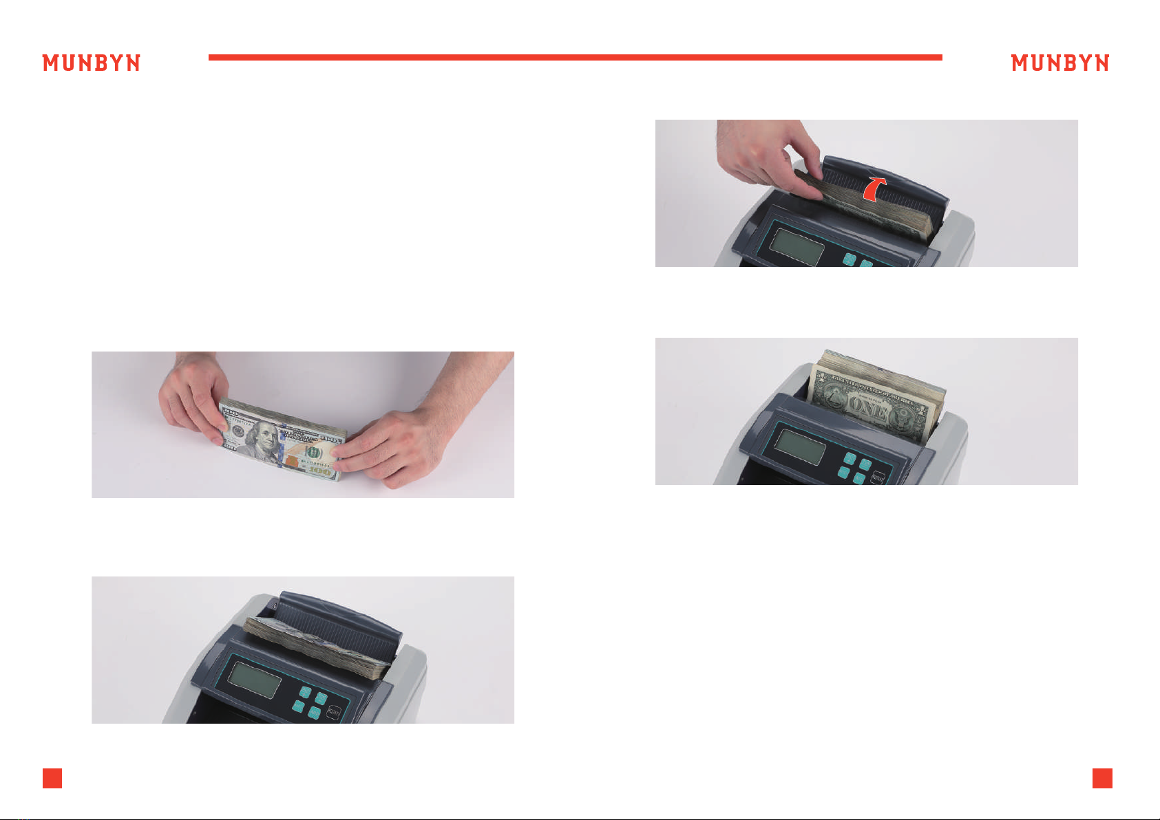
Place the bills in the hopper. The machine will start counting automatically.
The total number of bills counted will be displayed on the screen.
Empty the stacker, and refill the hopper. The machine will continue
counting, adding the new count to the total count.
To continue adding without emptying the stacker, just refill the hopper.
The machine will continue counting, adding the new stack of bills to the
partially full stacker. Please ensure you do not accumulate more bills
than the stacker can hold.
TIPS: ADD Mode can be used in combination with BATCH Mode and
Value Mode.
4.3.6. Detection Mode
5.1.1. UV Detection
5.1.2. MG Detection
The IMC51 is able to check for UV counterfeit bills using ultraviolet sensor.
Press the “FUN” key several times to select on and off,
refer to section 4.3.6 for details.
The counter will beep and stop counting when a UV counterfeit bill is
detected, and an ‘A’ message will be displayed. To continue counting,
remove the suspect bill, which will be the last one in the stacker, and
press the “RESTART” button.
The counter will start counting again, and will not add the counterfeit bill
to the count. This feature allows you to continue operation without losing
count, and is especially time-saving in the adding mode.
The IMC51 is able to check for MG counterfeit bills using magnetic sensor.
Press the FUNC key several times to select on and off, refer to section
4.3.6 for details.
The counter will beep and stop counting when an MG counterfeit bill is
detected, and a ‘b’ message will be displayed. To continue counting,
remove the suspect bill, which will be the last one in the stacker, and press
the “RESTART” button. The counter will start counting again, and will not
add the counterfeit bill to the count. This feature allows you to continue
operation without losing count, and is especially time-saving in the
adding mode.
Bills may stick to each other due to excessive dirt, folding, or various other
reasons. The IMC51 uses infrared light (IR) based technology to determine
when two bills are stuck together. Press the FUNC key several times to
select on and off, refer to section 4.3.6 for details.
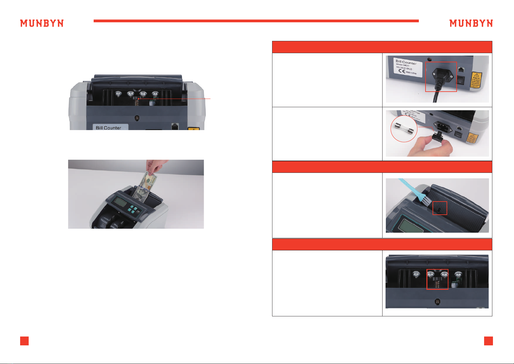
The IMC51 incorporates infrared light (IR) sensors that notify users if a half
note passes through the counting mechanism.
The counter will beep and stop counting when a double bill is detected,
and an ‘E’ message will be displayed. To clear the error, all bills must be
removed from the stacker. The screen will automatically be reset. All bills
in the stacker must then be placed back in the hopper and recounted.
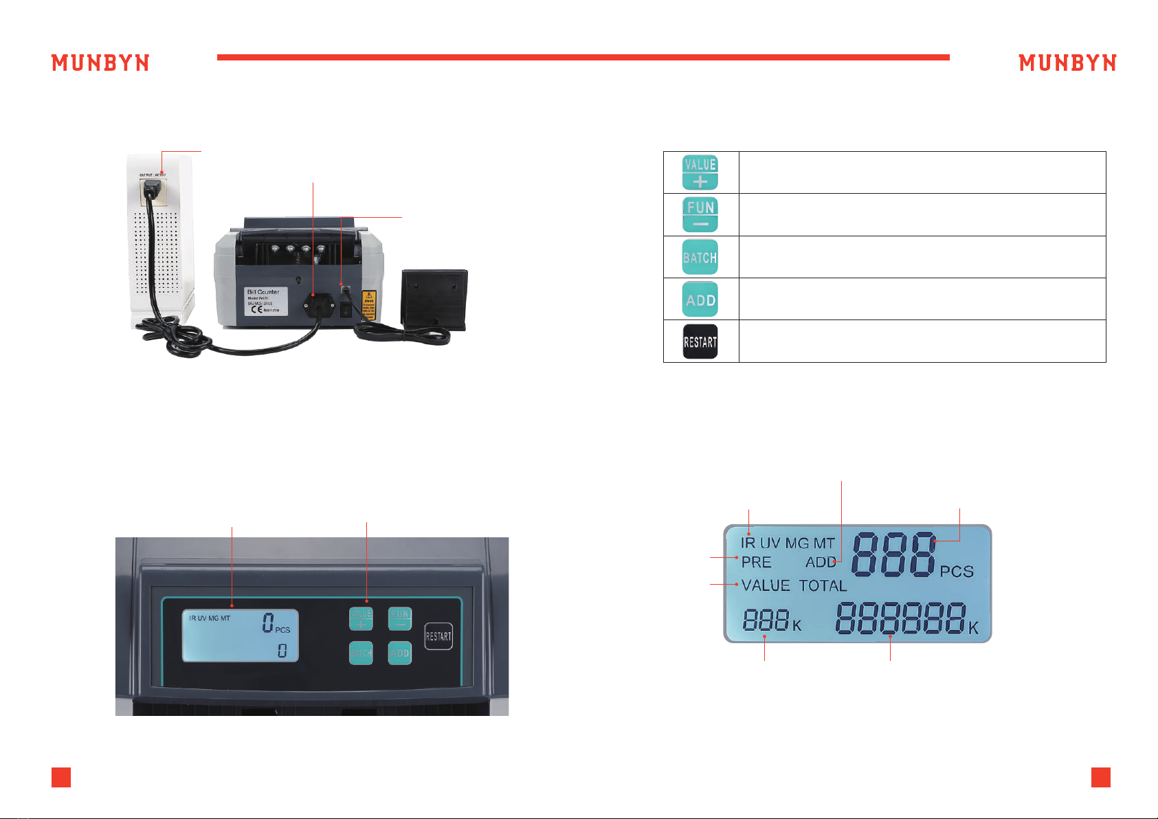
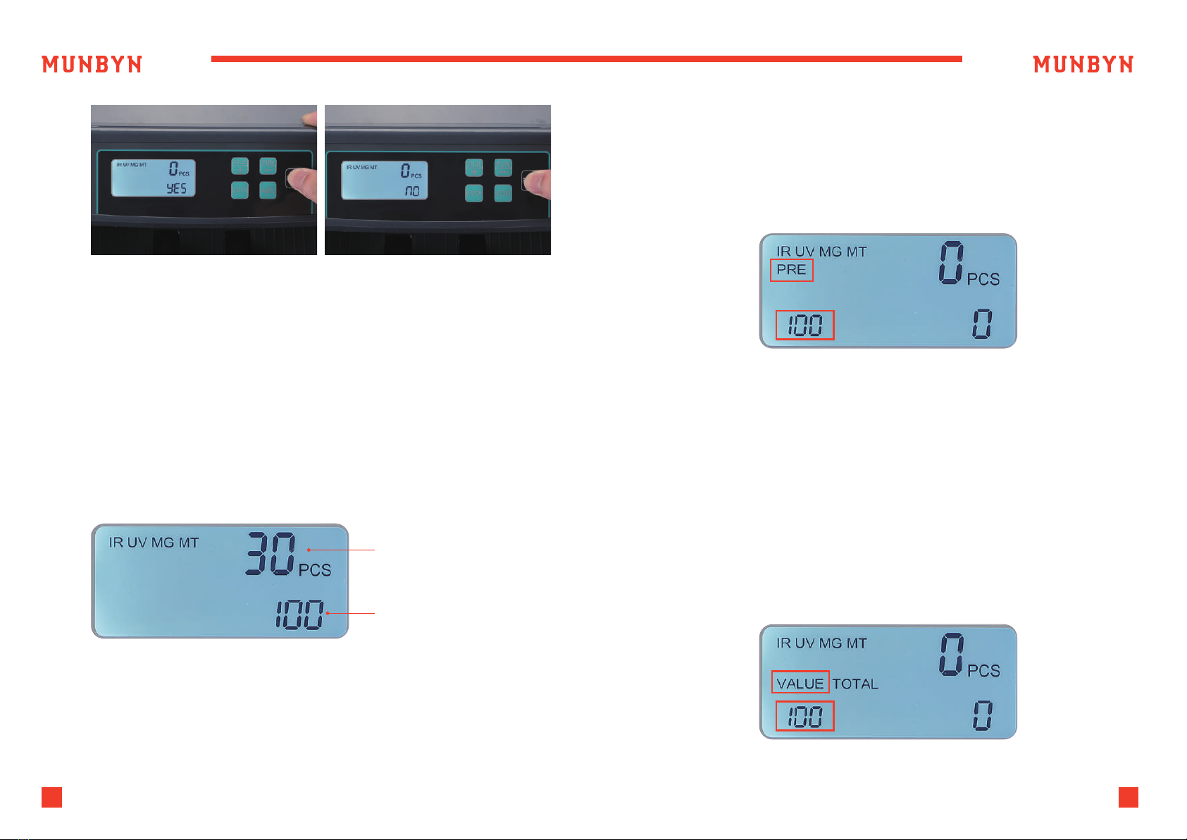
The FUNC button controls the inspection mode of the machine. Pressing
FUNC button can turn off MT, MG, UV and IR detection in sequence.
When all detection modes are turned off, the machine can only
count the number of bills. Pressing FUNC button again can turn on all
detection modes.
5.0. Detection Features
5.1. Counterfeit Bill Detection
5.2. Double Note Detection
5.3. Half Note Detection

11 Support: +1 650 206 2250 12
Support: +1 650 206 2250
The counter will beep and stop counting when a half bill is detected,
and an ‘H’ message will be displayed. To clear the error, all bills must be
removed from the stacker. The screen will automatically be reset.
All bills in the stacker must then be place back in the hopper and recounted.
The IMC51 utilizes a self-checking system that alerts you in rare cases when
several notes pass through the counting mechanism at once.
The counter will beep and stop counting when a chain note is detected,
and a ‘C’ message will be displayed. To clear the error, all bills must be
removed from the stacker. The screen will automatically be reset.
All bills in the stacker must then be placed back in the hopper and
recounted.
Power off, press “VAL” “START” 2 buttons at the same time and then turn
on machine, when the external display show “DEFAU”, it means machine
restore to factory settings.
The description of the error codes and the related handling methods are
shown in table 6-1.
5.4. Chain Note Detection
6.0. Maintenance and Troubleshooting
6.1. Factory Setting
6.2. Error Code and Solution
Error code
A Fake note detected by UV Remove the fake note from the
stacker, press “RESTART” to continue
CChain note or different
width note detected
Remove the suspicious note from the
stacker, press “RESTART” to continue
EDouble note detected
by IR
Remove the double note from the
stacker, press “RESTART” to continue
FDetection of incorrectly
placed bills at an angle
Remove the bill and press “RESTART”
to continue
H Half note detected Remove the half note from the
stacker, press “RESTART” to continue
FE1
Problem with hopper
sensor Problem with
the UV sensor
Clean the sensor or replace it Clean
the sensor or replace it
FE2 Problem with left
counting sensor Clean the sensor or replace it
FE3 Problem with right
counting sensor Clean the sensor or replace it
FE9 Problem with MG sensor Replace the MG sensor
FEA Problem with UV sensor Replace the UV sensor
b Fake note detected by MG Remove the fake note from the
stacker, press “RESTART” to continue
Reason Solution
When banknote feeding is unsmooth or banknote counting is inaccurate,
it can be solved by adjusting the vertical adjusting screw as well as the
gap between the resistance rubber and rubber wheel. Then you can put in
a banknote and hold, if you feel the pull, the machine is workable.
6.3. Hopper Plate Adjustment
Generally speaking, most of the above errors be caused by dust or dirt
inside of the machine, so keeping the machine clean is highly
recommended.
Table 6-1 Error Code

13 Support: +1 650 206 2250 14
Support: +1 650 206 2250
Before repair, please check the problems below.
NOTE: Before troubleshooting, please turn off the power switch and
unplug the outlet.
Turn it clockwise to decrease gap in order to add friction (tight).
Turn it anticlockwise to increase gap in order to reduce friction (loose).
Figure 6-1 Adjustable Screw
Check if the plug is well inserted
into socket
Check if the power fails or fuse burn out
Feeding Sensor covered in dust? Clean
Figure 6-2 Feeding Gap Adjustment with One Banknote
6.4. Common Trouble and Solution
Adjustable
Screw
Not working
Fail to start or stop normally
Hopper position adjusted improperly?
Counting Error

15 Support: +1 650 206 2250 16
Support: +1 650 206 2250
7.0. Technical Parameters
8.0. Contact us
Table 7-1 Technical Parameters
Measurement
Net Weight 3.3 KG
1100pcs/min
150 notes
150 notes
AC110V±10%
IR, UV, MG, MT
Counting Speed
Hopper Capacity
Stacker Capacity
Power Supply
Detection
282×239×145mm
Scan the QR code for Facebook
and WhatsApp online chat
MUNBYN provides 18 months warranty and lifetime free service.
If you encounter any issues with the product, please contact the
MUNBYN team to promptly receive troubleshooting tips or a
replacement.
Email: support@munbyn.com (24-7 online support)
Skype:+1650 206 2250 Whatsapp:+86 18144898200
Email: [email protected]om
Website: www.munbyn.com (how-to videos, warranty details)
Do not operate the unit in areas with high temperature or high humidity
since it may cause the machine to refuse to work or prevent it from
counting accurately.
- When not using the unit for a long period of time, remove the power plug
from the wall outlet.
-Never operate the unit under strong light.
-Clean the machine frequently after switching if off and unplugging
of the machine.
-Do not use this product in areas where it may be exposed to water
or other liquids.
-Unplug this product from the wall outlet before cleaning. Do not use liquid
cleaners or aerosol cleaners. Use a damp cloth for cleaning.
6.5. Maintenance
9.0. FCC Caution
This device complies with part 15 of the FCC Rules. Operation is
subject to the following two conditions: (1) This device may not cause
harmful interference, and (2) this device must accept any interfer-
ence received, including interference that may cause undesired
operation.
Any Changes or modifications not expressly approved by the party
responsible for compliance could void the user's authority to operate
the equipment.
Note: This equipment has been tested and found to comply with the
limits for a Class B digital device, pursuant to part 15 of the FCC
Rules. These limits are designed to provide reasonable protection
against harmful interference in a residential installation.
This equipment generates uses and can radiate radio frequency
energy and, if not installed and used in accordance with the instruc-
tions, may cause harmful interference to radio communications.
However, there is no guarantee that interference will not occur in a
particular installation. If this equipment does cause harmful interfer-
ence to radio or television reception, which can be determined by
turning the equipment off and on, the user is encouraged to try to
correct the interference by one or more of the following measures:
-Reorient or relocate the receiving antenna.
-Increase the separation between the equipment and receiver.
-Connect the equipment into an outlet on a circuit different from
that to which the receiver is connected.
-Consult the dealer or an experienced radio/TV technician for help.
Table of contents
Other MUNBYN Banknote Counter manuals