Musicmakers Dakota Mandola KIT User manual

DAKOTA MANDOLA KIT
651-439-9120
harpkit.com

WOOD PARTS:
A - Neck
B - Fingerboard
C - Heel Block
D - Tail Block
E - Clamping Block
F - 2 Short Ribs
G - 4 Corner Blocks
H - 2 Mid-Ribs
I - Long Tail Rib
J - 2 Dowels, 1/4” X 1”
K - 2 Clamping Wedges
L - Back
M - 2 Braces for Back
N - Front (Soundboard)
O - 5 Braces for Front
P - Bridge
Q - Spacer Block (11”)
HARDWARE:
40” Fretwire
1 White Side Marker Rod, 5/64”
8 Gold Geared Tuners
w/bushings & 10 screws
Set of Mandola Strings
Tailpiece w/3 screws
White Nut Material
3 Wood Screws, 1
-
5
/8”
2 Tiny Nails
Drill Bit, 1/16” for tiny screws
Drill Bit, 5/64” for Marking Dots
Drill Bit, 7/64” for wood screws
Drill Bit, 1/4” for dowels
Medium Donut Ring
Assembly Instructions
A NOTE ABOUT GLUE
We recommend assembling this kit with standard woodworker’s glue (such as Elmer’s Carpenters Glue or Titebond Wood
Glue). Don’t use Hotmelt glue, Superglue, 5-minute Epoxy, or the plain white School Glue for assembling the major wood
parts -- they are not strong enough for a high-tension instrument. There is no need to look for any special violin-maker’s adhe-
sive. You may, however, see epoxy or superglue recommended in one or two steps for installing non-wood parts.
Every time you use wood glue on this project, it is wise to have a damp rag handy for cleaning up afterwards. It is always best
to scrub away any excess glue that squeezes out of the joints before it dries, especially on the outside of the instrument. Keep
your hands and workbench as clean as possible too. Glue smudges will show up vividly on the finished instrument.
ASSEMBLY INSTRUCTIONS
_____1. CAUTION: PLEASE DO NOT OPEN THE SEALED PLASTIC BAG CONTAINING THE FRONT
AND BACK PANELS UNTIL YOU REACH STEP #14. These two parts need to be kept very dry until you glue
the braces on them. Check over your kit parts to make sure you have everything (see fig. 1 above). Contact us right
away if you are missing parts so we can rectify the problem without causing too much delay for you. We also recom-
mend checking off each step in the directions as you finish it. You might be skipping forward to another part of the
assembly while waiting for something to dry, and it helps to keep track of where you left off.
CUSTOMIZING OPTIONS
If you are an enterprising woodworker who wants to make this project special with
some sort of decorations, here are some ideas for you to think about. You may want
to order decorative materials now so you have them when you need them.
1 Medium Wood Rosette for the Soundhole, with Donut Ring
4 strips of Inlay Banding for trimming the Front and Back
2.
fig 1
DAKOTA MANDOLA KIT
A
B
C
D
E
F
H
G
G
G
G
L
M
N
O
P
Q
K
J
Q
F
H
I

_____2. Begin at the heel where the
body will join the neck. Place the heel
block and the clamping block together
and drill two pilot holes into the clamp-
ing block using the 7/64” drill bit pro-
vided, as shown in figures 2a and 2b..
Tools Required for This Stage
Masking Tape Small C-clamps Cordless Hand Drill
Plastic Grocery Bag Spring Clamps Phillips Driver Bit
Wood Glue Damp Rag 7/64” Drill Bit
clamping block
heel block
7/64” drill bit
Hold blocks
carefully on
a flat sur-
face so they
are flush
with each
other as you
drill pilot
holes.
_____3. Find the two short ribs and look carefully for pencil markings that show “H” at one end. ese are the
ends that get glued to the heel block. Orient these pieces carefully: e end of each piece marked “H” will be
clamped against the heel block with the pencil marks facing the inside of the body (g 3a).
Tape the two short ribs to the heel block WITHOUT GLUE rst, and test the shape against the soundboard (front
piece) of the instrument. It is possible to fasten these pieces backwards and have them ared the wrong way!
_____4. When everything checks out, put glue on the end of each short rib and tape them carefully back against heel
block as shown in fig 4a.
CAUTION: Don’t glue the
clamping block to this as-
sembly! Put a thin plastic
barrier between the clamp-
ing block and the heel block
so you can remove the
clamping block later.
Install the screws into the
clamping block to draw parts
firmly together until the glue
dries (fig 4b).
Wood Glue
short ribs
with “H”
marks
against
heel block Tape the short
ribs in place
WITHOUT
GLUE first.
Test the shape
to make sure it
matches the shape
of the sound-
board.
“S” mark
at free end
Masking Tape
Plastic
Bag Scrap
3.
fig 2a fig 2b
fig 3a fig 3b
fig 4a fig 4b
GLUING THE BODY FRAME

_____5. Find the 4 corner blocks. These are all the same, so they are interchangeable. Test-fit a corner to one of
the short ribs without glue to make sure your clamp will hold it firmly in place (fig 5a). We have included a couple
clamping wedges made of scrap wood in case you need them. When satisfied with the fit, glue and clamp a corner
to each short rib, making sure the rib fits all the way into the corner of the ledge (fig 5b).
_____7. Continue by gluing the next two
corner blocks at the open ends of the mid-
ribs, as shown (fig 7).
4.
tight fit
fig 5a fig 5b
Allow at least 30 minutes dry-
ing time.
After the corners are dry, you
can remove the clamps. You
can also remove the screws
holding the clamping block to
the heel block.
_____6. Now you can glue the two mid-ribs
into the corners. These ribs should flare out-
ward, as shown (fig 6). They are symmetrical,
so it does not matter which end you glue to the
first corners. Notice the use of clamping wedg-
es to make it easier to clamp the parts together.
CAUTION: It’s possible to glue these parts
together crooked! Make sure all the parts are
pushed firmly into the corner blocks, that the
parts remain flush with each other, and that the
entire assembly remains flat. Lift the assembly
up and look carefully at each seam to make sure
it is tightly fit. Also make sure the whole as-
sembly will lay on your flat work surface with-
out rocking.
clamping wedge
corner block
corner blockclamping wedge
fig 6
fig 7

5.
Tape a clamping wedge to the joint and and then add your clamp, as shown in fig 9b, still without glue.
If the joint comes together correctly, then remove the clamp and tape so you can repeat the process with glue. Allow
this joint to dry another 8 hours (because it is under tension).
_____8. Glue just one end of the long tail rib to one corner block, as
shown (fig 8). Let the entire assembly dry overnight (or 8 hours) before
proceeding to close the frame. If you proceed too quickly, the glue is
likely to break at one or more of the corners. It takes about 8 hours for
most woodworking glue to harden completely.
While you are waiting for this assembly to dry, you can skip to step #34
(page 15) and begin shaping the neck and peghead.
_____9. When this assembly has fully dried, you can use masking tape to
pull the final corner together roughly (fig 9a). Do this WITHOUT GLUE
first, just to make sure everything works easily for you, and no corner blocks
break free. fig 8
_____10. When dry enough to remove the last clamp, measure 7-3/8” from each end of the large curved rib and
mark it for locating the tail block (fig. 10a). Please note that this may not look exactly centered at this point because
the frame may be slightly skewed one way or the other. You’ll straighten it in the next step. Glue and clamp the tail
block in place as shown in fig 10b.
fig 10a
fig 10b
fig 9a
masking tape
fig 9b
nice tight glue joint
While waiting for
this last corner
to dry, go back
to shaping the
neck -- it’s good
to spend time
smoothing it to
fit your hand.
tail block
Center the
tail block
between
your
marks.

6.
CAUTION: FLAT EDGE UP! Pay attention to how you orient the
kerfing strips (fig 12b). Keep the flat edge flush with the edge of
the rib, or a tad higher, and wipe off excess glue with a damp rag.
Try to keep glue off the outside of the ribs, as that will show on the
finished instrument.
Glue and clamp kerfing in place using clothes pins or small spring
clamps (fig 12c). It may be helpful to add rubber bands to your
clamps to increase clamping pressure. Allow at least 30 minutes
for drying before removing clamps.
Glue kerfing around the entire inside frame, on both front and back edges,
as shown in fig 12c.
_____13. When the kerfing is dry, make yourself a long sanding block by
gluing 60 or 80 grit paper to the face of a straight scrap of wood at least
12 inches long and 3 or 4 inches wide.
This type of sanding block will rest across the frame of the body, allowing
you to sand the edges perfectly flat (fig 13). The goal is to remove glue
blobs and to sand any high spots down flush with the ribs. fig 13
use plenty of clamps
fig 12c
Tools Required for This Stage
Lots of Spring Clothes Pins (or Small Spring Clamps)
Rubber Bands, if needed
Wood Glue
Damp Rag
Sanding Block, 60-80 grit (see fig 13 below)
ADDING INNER KERFING
_____12. Add inner kerfing inside the ribs to provide a wider “shelf”
of wood for gluing the front and back panels to the frame. These
wood strips are “kerfed” to make them flexible enough to follow the
curved ribs.
Cut or break the kerfing into the approximate size needed for each
space -- it does not need to fit perfectly (fig. 12a). In fact, it is easier
if you cut it slightly shorter than the space so you can easily slide it
into position.
kerfing strips
fig 12a
kerfing flush with edge of rib, or slightly higher
fig 12b
_____11. Now you need to stretch the frame a little to fit the spacer
block between the heel and tail, as shown in fig 11. DO NOT GLUE
THE SPACER! This is just a temporary piece to hold the instrument
in the proper shape until you glue the soundboard in place. You will
remove it in step #25. Use clamps to hold each end if necessary.
fig 11
Spacer Block
NO GLUE!

7.
PREPARING THE BACK PANEL
_____14. NOW YOU CAN OPEN THE SEALED BAG AND REMOVE
THE BACK PANEL (DARKER MAHOGANY PIECE). IF YOU ARE
WORKING IN A HUMID ENVIRONMENT, PLEASE STORE THE
FRONT PIECE (SOUNDBOARD) IN AN AIR-CONDITIONED (DE-
HUMIDIFIED) PLACE UNTIL YOU GET TO STEP #16.
Center the frame of the instrument on the inside face of the back panel
and outline the inside edges onto the back panel with a pencil, as shown
in fig 14a. Note the center lines at each end of this panel, and the two
horizontal lines marking the positions of the inner braces.
Once you have the outline of the instrument on the back panel, you can
position the two back braces over the lines marked and check how they
fit. If they cross your outline, mark where to trim them so they will not
interfere with the kerfing strips inside the frame (fig 14b).
NOTE: The two back braces are arched on the bottom so that when
you clamp them to the back, the back will become arched.
Use a sharp chisel or razor knife to trim the braces to length. Note:
Some builders may prefer to cut little “pockets” (notches) in the kerfing
to receive the ends of the braces. That is the more professional method of
fitting, but it is more difficult than trimming the braces shorter.
Then you can glue the braces in place, taking care to keep them from slid-
ing out of position under clamping pressure.
HINT: Use masking tape to hold the braces in place while you put a
clamp at each end (Fig 14c). This will produce an arched back because
of the curve in the braces. Double-check the middle to see if you might
need to add some weight in the center to achieve a firm glue joint along
the entire brace. You can prop the back on a block of wood to support
the middle, and then add weights to the center of the braces, if necessary.
Tools Required for This Stage
Pencil Spring Clamps
Wood Glue Chisel or Razor Knife
Damp Rag MaskingTape
spacer block
fig 14a
center line
fig 14b
fig 14c
Mark and cut
braces to length.
Use tape to keep
braces from
slipping out
of position when
adding clamps.
CAUTION: Don’t glue the back to the frame yet!
We glue the soundboard in place first (next page).
Store the back panel in an air-conditioned space until
you need it again near the end of the project. That’s
when you will close the box by installing the back.
NO GLUE
ON
SPACER

8.
PREPARING THE FRONT (SOUNDBOARD)
Tools Required for This Stage
Pencil Spring Clamps
Wood Glue Chisel or Razor Knife
Damp Rag MaskingTape
Sandpaper (60-80 grit)
_____17. (OPTIONAL)
If you purchased
a decorative rosette for the sound hole, you’ll
need to glue a “donut ring” (fig 17a) inside the
sound hole now to provide a ledge for gluing the
rosette in place. It is easiest to see the correct
position of the donut ring if you look from the
outer face of the sound board (fig 17b). Glue
this ring to the inside of the soundboard now,
before installing the braces.
fig 17a fig 17b
fig 19
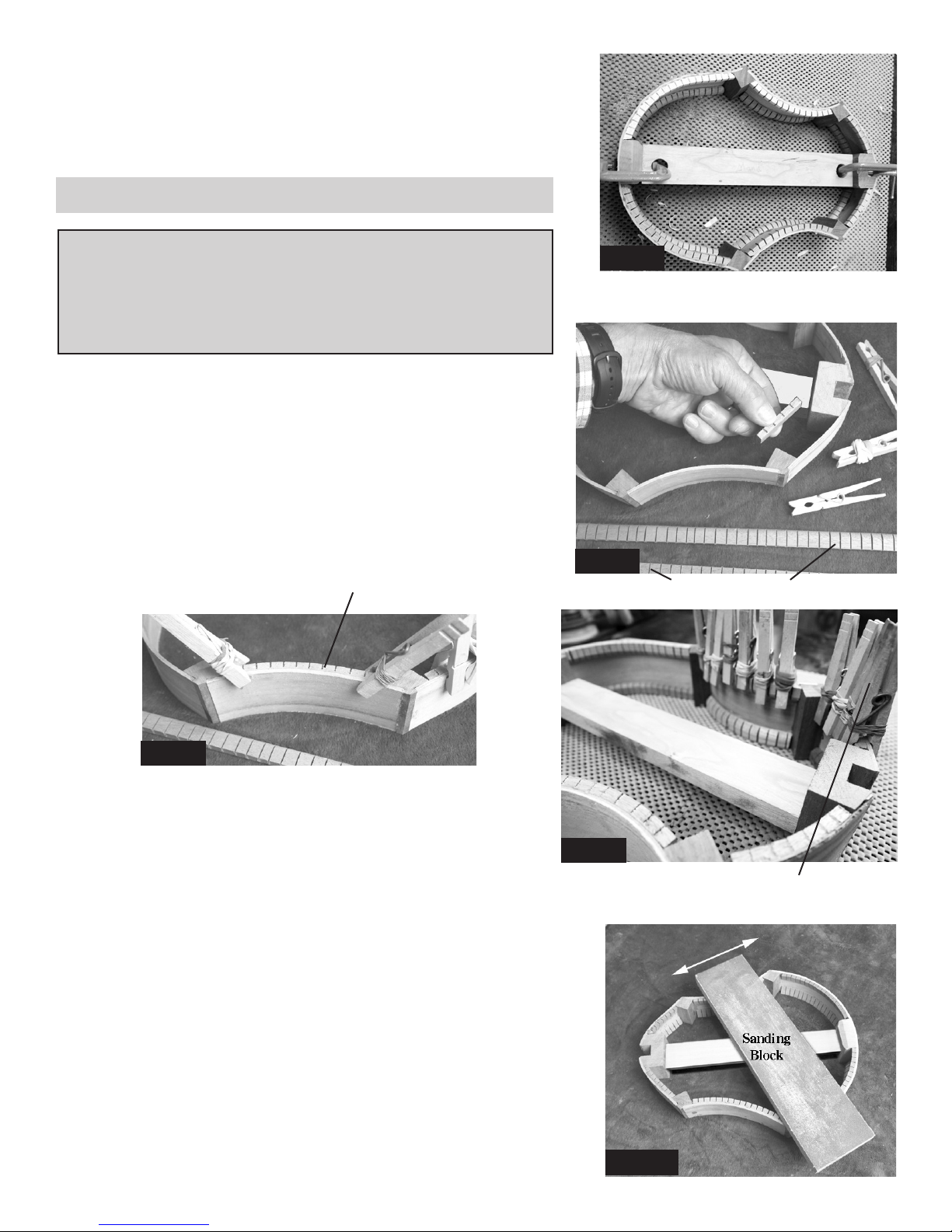
_____15. We highly recommend making
yourself a clamping pad for the body of the
instrument out of 3/4 plywood or particle
board (fig 15). Cut it at least the size of the
soundboard, or a little larger. fig 15
Clamping Pad
3/4” thick
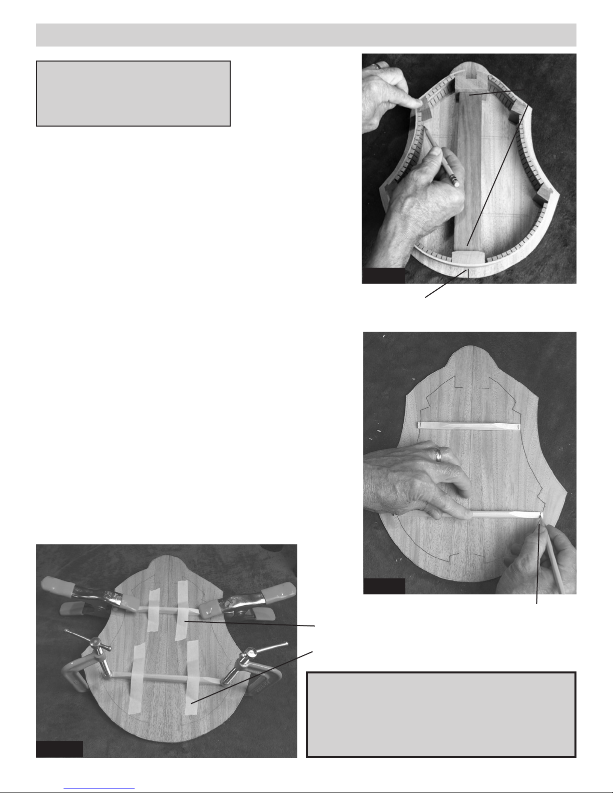
_____16. The inside face has pencil marks showing the placement of the braces.
Place it on your work table with the inside facing up.
Center the frame of the instrument on the soundboard and outline the interior in
pencil (fig 16), just as you did for the back panel. Make certain the frame is cen-
tered in relation to the sound hole and the tail end. Slide the frame up toward
the top of the panel to make sure there will be room for the top brace and
the “donut” for the rosette.
Notice the Center Lines!
fig 16
Pencil
Outline
_____18. Find the two braces that are notched to fit
together forming an “X” (figs. 18a & 18b). These can
be joined two different ways, and we want the longer
legs to be spread as wide as they can go (fig 18a).
This will give you the maximum bracing strength on
the soundboard. Test fit the X to the soundboard, just
to be sure you have it correct.
fig 18a
THIS
fig 18b
NOT THIS
_____19. Position the X braces in place first, without glue,
and then arrange the three shorter ones as shown in fig. 19.
Trim the ends that are too long, just as you did for the back
panel.
When satisfied with the fit, glue and clamp the X braces in
place first, making sure to put glue in the joint where they
cross. Use clamps and/or weights to hold the X braces in
place firmly.
When the X braces are dry, go ahead and glue the other
small braces too, as shown in fig 19. fig 20a
IMPORTANT NOTE ABOUT SOUNDBOARD
The front panel (soundboard) is the lighter colored piece made of solid Sitka Spruce,
and has a sound hole cut through it. If this panel has been exposed to high humidity
for more than a few hours, you will need to dry it out in an air-conditioned (de-
humidified) room for a few days to shrink the grain. This will help prevent cracks
from developing in the future. Hint: Another easy way to dry it out is to place it in
the oven at low heat (200 degrees) for 6-8 hours. Put clean tin foil under it to protect it
from any grease on the rack.

9.
_____22. Test fit the soundboard to the
frame, looking carefully around the entire
circumference to make sure the sound-
board will make good tight contact with
the edges of the ribs all the way around
(fig 22).
If you find a blob of glue or other ir-
regularity or unevenness that prevents a
tight fit, go back to step 12 and use your
coarse sanding block to level off the edg-
es of the ribs. fig 22
Tight fit when pressed together
_____23. Continue test-fitting the frame to the sound-
board WITHOUT GLUE, carefully lining it up on the
center of the soundboard. Leave the spacer block in place
for this step so the body maintains the proper length and
shape (fig 23).
Take your time here. Darken the center lines on each
part, if necessary, so you can easily see when the frame is
centered on the front panel.
Outline the outside of the frame on the soundboard
in pencil when you have it positioned where you want
it. This will help you re-position quickly when gluing.
Make sure you have enough clamps to do the gluing job
shown in step 24 -- test them to make sure they open far
enough and reach in far enough to press the frame down.
GLUING FRONT (SOUNDBOARD) TO FRAME
Tools Required for This Stage
Pencil 6 Clamps (minimum)
Wood Glue Damp Rag
Clamping Pad
NOTE: There is no front or back to the frame until you glue the front to
one edge, so you can choose either edge.
fig 23
Line up centerlines
DRY FIT
FRAME
TO
SOUND
BOARD
NOTE: We always clamp the frame down against the sound-
board, as shown here, rather than placing the soundboard on top
of the frame. This leaves everything open and visible while you
install the clamps so you double-check for proper alignment as
you work. It also ensures that whatever excess glue squeezes out
around the edges will not run down the outside surface of the ribs
and make a big mess to clean up.
_____20. Now you can taper the edges of the X-braces if you like,
using a chisel, coarse sandpaper or a sharp knife (fig 20a). We recom-
mend leaving the braces full height for stability, but you can bevel the
“shoulders” to lighten them up a little. A lightweight soundboard will
sound the best.
We also like to chamfer (bevel) the inside corners of the corner blocks
and the tail block (but NOT the heel block) to give the soundboard a
little more room to vibrate (fig 20b). Basically, we like to have about
the same amount of glue surface at each corner as there is on the kerf-
ing strips. Us a file or coarse sanding block to do this on both sides
(front and back) of the frame to achieve the best sound. fig 20b
chamfered blocks

10.
_____24. When you are ready to proceed, squirt a good
bead of glue all the way around the frame, including the
corner blocks, heel block and tail block, as shown in figure
24a. You want enough glue so that a little excess will
squeeze out when the parts are clamped.
Then flip the frame upside down and replace it over the
soundboard within the outline you drew in step 23.
Clamp the heel and tail ends first, making sure the center-
lines match up. Then put a clamp on each corner piece,
as a minimum (fig 24b). If you see areas that need more
pressure, add more clamps.
Allow 2 hours for drying before removing clamps.
fig 24a
fig 24b
_____25. When this assembly has dried, remove the
spacer block and save it for later (Step 41).
_____26. Trimming the excess soundboard material flush
with the ribs of the instrument requires some special care.
DO NOT attempt to cut off the overhang with a hand-held
jigsaw or a coarse hand saw. The spruce wood is fragile,
so you must work it carefully.
There are several possible tools for this delicate step, and
we’ll try to give you some guidance for whichever one
you might have available. If you don’t have any of these
tools, this is a great excuse to go out and buy something!
OPTION #4: ROUTER (figs 26a & 26b): This is our preferred trimming tool because it is fast, safe and accurate.
Take care, however, to move the router in a clockwise direction around the soundboard (fig 26-b). This is called a
“climb cut” because the router bit is pulling the machine that same direction, “climbing” through the wood. If you
push the router against the spin of the bit, you will likely chip the soft wood and cause damage to the edges. You
don’t need a large router for this step, but you can certainly use a larger one than shown here.
OPTION #1: HAND COPING SAW -- If you are working with just hand tools, a cheap coping saw will cut the
excess soundboard very easily. We recommend trimming a little wide, leaving 1/8” or so overhang that can easily
be sanding down flush.
OPTION #2: BAND SAW -- If you have a bandsaw available, it will do this job very quickly. But be very careful
not to cut into the frame of the instrument. A band saw could ruin the whole project in the blink of an eye!
OPTION #3: BELT SANDER -- If you have a stationary belt sander, you can sand away the excess soundboard
material quite easily. But take care to prevent sanding too deeply -- you could gouge the frame if you are not
watching closely.

11.
Router
Flush-trim bit
Roller bearing follows ribs
fig 26a fig 26b
Move router clockwise around instrument, as shown.
SANDING BLOCKS
Please note that however you trim the soundboard, you will still
need to do some careful hand sanding to finish the job. Thank-
fully, spruce is soft, so it sands quickly with a sanding block.
We recommend gluing sandpaper to a flat piece of wood for
sanding the outside curves and taping some sandpaper around a
curved item (like a can) for sanding the inside curves (fig 26e).
Use coarse sandpaper (60-80 grit) for removing excess wood,
and then 100-150 grit for smoothing.
Sand the remaining excess soundboard flush with the sides of the
body, as shown in figs 26f and 26g. Make sure the corner blocks
are flush and smooth with the ribs too.
fig 26e
fig 26f
fig 26g
CAUTION:
Be care-
ful to keep the heel
square to the top when
you are sanding (fig
26h). This will be very
important when fitting
the neck and fretboard
in place later.
fig 26h
Square
Sand walnut cor-
ner blocks flush
and smooth too.

_____28. If you wish to decorate the edges of the soundboard all around the top of the
instrument, you will need a router with a small straight bit that can cut a ledge for the in-
lay strips. A nice inexpensive way to do this is to adapt a 1/2” flush-trim router bit with
a 3/8” diameter roller bearing, so the cutters extend 1/16” beyond the roller, as shown
in figure 28a. We have these router bits and bearings available on our website at www.
harpkit.com/inlays.
When you put this bit into your router, you only want the cutting edge to be as far above
the router base as the width of your inlay banding (fig 28b).
Be sure to test your cut on a piece of scrap wood first! The router bearing should follow
the edge of the wood, and the cutting blades should make a shallow ledge just the right
size for the inlay strip (fig 28c).
fig 27a fig 27b
beveled
edges on
spruce top
_____ 27. Use a flat file or razor knife to finish cleaning out the notch in the heel block, as shown in figures 27a and
27b. Note how we beveled the edges of the spruce top (fig 27b). This will help make sure the neck seats fully into
the mortise slot.
OPTIONAL DECORATION: INLAY BANDING
fig 28b fig 28c
Tools Required for This Stage
Pencil Razor Knife or Chisel Wood Glue Masking Tape
Router Inlay Bit Damp Rag Sandpaper (150 grit)
Wire Cutter
fig 28a
Inlay Bit
12.

_____29. When satisfied with the depth of your cut, you can rout a
ledge around the circumference of instrument. Make sure to move
the router in a CLOCKWISE direction, just as you did when flush
trimming the spruce soundboard (fig 29).
If your inlay banding is more than 1/8” wide, you will be cutting
into the mahogany ribs too. That’s just fine. There’s plenty of
thickness available, and the inner kerfing strips add extra strength
to these edges also.
fig 29
_____30. Once the ledge is cleanly cut all the way around the perimeter, you can begin to install the inlay strips in
short sections that are mitered at the corner blocks, as shown in figs 30a and 30b).
Use a sharpened pencil to mark where to cut the strip, drawing the line at an angle that approximately bisects the
corner, as shown in fig 30b.
fig 30a fig 30b
_____31. Cut the strip a little beyond your mark (fig 31a), then use a razor knife or sharp chisel to make a more
precise cut on the line (fig 31b). If you need to change the angle a little or shave it a hair shorter, do that on a sanding
block, as shown in fig 31c.
fig 31a fig 31b fig 31c
13.

_____32. When you have the first strip ready to install, squirt a thin bead of woodworker’s glue into just that short
section of the ledge where the strip will fit (fig 32a). Use masking tape to hold the strip tightly in place, as shown in
fig 32b.
HINT: Pretend the masking tape is elastic -- pull the tape both ways as you press it down against the wood.
This will pull the inlay strip all the way into the ledge.
fig 32a fig 32b
_____33. Now you can fit the next piece of inlay in place, as shown in fig 33a. Notice the pattern of your inlay band-
ing -- your inlays will look the most professional if you trim the end of the second strip to continue the pattern of the
first strip (fig 33b). You can make this decoration appear to be seemless if you are careful and patient.
fig 33a
Continue around the instrument in this way, leaving
the tape in place for 8 hours before removing. Note
that the neck and fingerboard will cover the ends at
the heel block, so the strips can stop slightly short of
the mortise slot (fig 33c).
Once dry, you’ll want to remove the tape and sand
the edges clean and smooth, making sure to remove
all excess glue that squeezed out around the inlay
strips. Don’t worry about sanding the inlay strips
themselves. The colors go all the way through, so
you can clean them up and smooth the surface with-
out removing the pattern. Just don’t sand too ag-
gressively on the inlay strips -- they are less than
1/16” thick!
fig 33c
14.
fig 33b

15.
PREPARING THE FINGERBOARD
_____34. We like cutting the wide end of the fingerboard to make it more interesting, but you can leave it square.
Figure 34 shows some other options that are common for mandolin fingerboards. The simplest option is to cut a 3”
diameter arc, as shown at left, to mirror the shape of the soundhole. You can use a soup can as a pattern for that.
Make the cuts with a bandsaw and
then smooth out the edges with
sandpaper.
NOTE: Before installing frets, take
time to make sure the face of the
fretboard is nice and smooth. Sand
with progressively finer sandpaper,
starting with about 180 or 220 grit.
We go all the way to 600 grit to pol-
ish the rosewood nicely. You won’t
be applying finish to the playing sur-
face, so this is your chance to shine
it up nicely.
_____35. Trim your fretwire a little longer than necessary to reach across
the fingerboard (fig 35a). Then use a light hammer to tap the fret into the
slot (figs 35b & 35c).
HINT: It helps to place the fingerboard on a very solid surface, such as an
anvil or a cement floor. That way the frets will drive in more easily and uni-
formly. Don’t pound too hard, or you will likely distort the fretwire and/or
dent the fingerboard.
It is is important to seat the frets fully into the slots so the underside of the
fret rests on the wood. Use the curve in the wire to your advantage, tapping
the middle of the fret home after the ends are in place. That way the arch
helps prevent the ends from bending back up out of the slot.
If you over-work a fret, just remove it and use a pair of pliers to restore the
shape before making a second attempt.
fig 35a
fig 35cfig 35b
fig 34
A NOTE ABOUT FRET MARKING DOTS
This kit comes with side markers that you will install along one edge of the fingerboard later (step 58),
but we also offer mother-of-pearl dots in our catalog (the 5 mm size is best for a mandolin). If you want to
inlay fret-marking dots on the front of the fingerboard, you should do that now, before installing the frets.

16.
_____36. Clip the frets as close to the wood as you can (fig 36a), and then
sand the sharp metal ends down flush with the wood. Fretwire is quite soft
metal, so you can sand it or file it quite easily. We hold the fingerboard up
against a belt sander for this operation, but you can do the job by hand with
a flat file (fig 36b) or coarse sanding block (80 - 100 grit). HINT: Cloth-
backed sandpaper is stronger than paper-backed types for sanding metal.
fig 36a
fig 36b
fig 37
_____38. Once the fingerboard is done, you can
glue it to the neck (we wait on shaping the neck
until the fingerboard is attached).
The narrow end of the fingerboard should end
about 1/8” before the angle of the peghead, giving
just enough flat surface on which to place the nut
(fig 38). Hold the parts in place and draw a pencil
line on the neck to mark the end of the fingerboard.
_____39. Tap 2 tiny nails partway into the neck,
leaving most of the nail standing above the wood,
as shown in fig 39a. These will help keep the fin-
gerboard aligned when you glue it to the neck. The
exact placement is not critical for these nails.
Then clip off most of the exposed nails, leaving
just a short stub poking above the surface of the
neck (fig 39b).
_____37. Put a bevel on the ends of the frets by tilting your file to a 45 de-
gree angle, as shown in fig 37. Run your hand along the edges to check for
smoothness. It is important to remove all sharp metal ends and make the
edges flush and smooth.
fig 38
fig 39a fig 39b
GLUING THE FINGERBOARD TO THE NECK
Tools Required for This Stage
Pencil Wood Glue Sanding Block (150 grit)
Lots of Clamps Clamping Blocks Hammer
Damp Rag Putty Knife Wire Cutter
NUT
Pencil Line

1 7.
_____40. Carefully align the fingerboard on the neck, checking that the narrow end matches the pencil line by the
peghead, and the sides are aligned with the neck as closely and evenly as possible. Yes, the fingerboard is standing on
those two tiny nails! Now press (or tap) the fingerboard over those two nails so the tiny nails punch a depression in
the underside of the fingerboard (fig 40a). This will enable you to re-position the fingerboard in exactly the same place
after applying glue. The nails will keep the fingerboard from slipping out of place as you apply clamping pressure.
Make sure there is still room for the nut at the end of the fingerboard (fig 40b). It should stand on a little flat shelf
next to where the peghead slopes down.
fig 40a fig 40b
_____41. Gather a bunch of clamps and scraps of wood to use as clamping blocks before doing any gluing. You
want to be well prepared for this step so you don’t end up with gaps between the neck and fingerboard. In fact, it
would be smart to experiment with your clamping system before applying any glue. You may have different types of
clamps than we use, so make sure your system will work well, and have the clamps open to approximately the right
size to save time.
Rehearse installing
plenty of clamps by
dry-fitting the finger-
board with clamping
blocks (fig 41a).
Notice how we use
long narrow scraps
of wood on each side
of the fingerboard to
make sure we can press
both edges of the fin-
gerboard firmly against
the neck (fig 41b).
fig 41a fig 41b
fig 42a fig 42b
_____42. When satisfied with your clamping set-up, apply glue to the neck, as shown in fig 42a. Then clamp the
fingerboard again and check for any open gaps along the sides. Wrap a damp rag around a putty knife to clean excess
glue from the each end of the fingerboard for the nut and the heel joint (fig 42b). Allow 8 hours for drying.

18.
SHAPING THE ASSEMBLED NECK
We use a combination of tools for this process. A 3” drum
sander will remove a lot of material quickly (fig 43a), but
you’ll want to be careful to avoid creating bumps and dips
in the wood.
You can do all the shaping without power by using files (fig
43b), sanding blocks, sharp chisels, and/or razor knives (fig
43c).
_____44. When the major shaping is done, switch to hand
sanding, with the grain, beginning with 80 grit paper and
then 150 grit to remove your tool scratches (fig 44).
fig 43a
fig 43b
_____43. We have done basic shaping on the neck for you, but there is some hand-
work to be done to create the profile you like and for smoothing everything out nicely.
We recommend taking your time with this step, checking how the neck feels in your
hand for playing. If you have a similar finished instrument available to look at, you
can try to copy the same shape on this kit, or you can customize this kit to fit your grip
more comfortably.
Some people with large fingers prefer to keep the fingerboard full width, but you can
trim it narrower if you like by removing equal amounts of wood from each side.
fig 43c
fig 44
Tools Required for
This Stage
Curved File
Flat file
Sanding Block (150 grit)
Drum Sander (optional)
Razor Knife
POINT OF INTEREST
People sometimes ask if this in-
strument has an adjustable truss
rod. We build the neck with two
well-cured pieces of mahogany
for stability, and then we inlay a
carbon ber reinforcement bar
down the centerline for added
stability. We think this makes a
stronger neck than one having a
long open slot for an adjustable
truss rod.
Razor Knife

19.
FITTING THE NECK TO THE BODY
_____45. Test-fit the neck to the body (fig 45). The goal is to have no visible
gaps where the neck meets the ribs, and the fingerboard should lay flat on top
of the soundboard without bending. fig 45
Tools Required for This Stage
Electric Drill 7/64” Drill Bit Masking Tape
Screw Driver Sanding Block (150 grit) Ruler
Pencil Chisel or Razor Knife Square
Wood Glue 2 Clamps Clamping Pad
_____46. Use the 7/64”
drill bit to drill one pilot
hole into the neck from
inside the body (fig 46a).
We put masking tape on
the drill bit to mark the
length of the screw so we
don’t drill too deeply!
Then use a hand screw driver to install two 1-5/8” wood screws provided. NOTE: We call for a hand screw driver
here because you don’t want too much power on this screw -- you might strip out the pilot hole in the neck (fig 46b).
If you cannot draw the parts together firmly, however, use a power drill very carefully!
_____47. Now flip the instrument over and hold a straight-edge or ruler along
each side of the fingerboard so you can trace the path of those edges onto the
soundboard with a pencil (fig 47a). Compare those lines with the sound hole
and the centerline to see how straight the neck is with the body (fig 47b). The
centerline should be centered between the two outer lines.
fig 46a fig 46b
fig 47a fig 47b
Take note that the back is not yet installed, so it is still possible to flex the ribs a little, if necessary, to achieve a good
fit here. So before you make drastic adjustments, we recommend installing one wood screw to hold the parts together
while you check the alignment of the neck to the body.
_____48. If you need to tilt the neck one di-
rection or the other to get it aligned with the
centerline of the soundboard, mark which
side of the heel joint needs sanding. Then
remove the neck from the body and sand
the surface of that particular rib, using a flat
sanding block (fig 48a), and checking to
make sure you keep the surface square with
the soundboard (fig 48b). Test fit the neck
again to see how your efforts paid off. A
little trial and error like this should bring the
neck into alignment. fig 48a fig 48b
Square

20.
_____50. Now is a good time to “level” the tops of all the frets. Use a large flat mill file, resting on the FRETS, to
wear down any that are too high (fig 50a). Check your progress frequently to see which frets are being cut and which
ones are not. As soon as each fret has been scratched lightly with the file, you may consider them all level.
fig 50a
After leveling the tops with a file, you can do a decent job of dressing the
frets by wrapping sandpaper around your fingers, as shown in fig 50b.
Start with about 180 grit paper, sanding back and forth along the length of
the fingerboard. This will help round over the frets again, reducing the flat
areas on the frets.
Change to progressively finer sandpaper (say, 300 grit, 400 grit, and then
600 grit) to smooth and polish the frets nicely.
fig 50b
Then add a couple clamps to hold the fingerboard
down fully against the soundboard (fig 49c).
Notice the scrap of wood used for preventing
the clamps from damaging the fingerboard.
_____49. When satisfied with the fit, you can install the neck perma-
nently with wood glue. Squirt glue on all the contact surfaces: tenon,
shoulders of heel, and fingerboard (fig 49a). Install the neck using the
same screws (fig 49b).
fig 49b
fig 49a
Glue
fig 49c
Clamping Pad
Clean up
glue before
it hardens!
Notice that the neck contacts the body more firmly on the outer edges of the
joint than in the center (fig 48c). We design the joint this way on purpose,
so it will be easier for you to achieve a nice fit on the outside.
Check carefully along the heel joint to see if there are any gaps showing on
the outside (fig 48d), and make pencil marks where you want to remove a
little wood so the entire seam closes up nicely. Then use a flat sanding block
or file to make very slight adjustments to the outer edge of the heel (fig 50c)
until you like the way the parts fit. Be careful not to overwork this. It should
only require very light sanding.
fig 48d
Tight
Fit
Slight
Gap
Sanding
Block
Sand the areas where the fit is
tight in order to close gaps in
other areas.
Check how the fretboard rests
on the front too.
fig 48e
fig 48c
Gaps
Tight
Fit
Table of contents
Other Musicmakers Musical Instrument manuals

Musicmakers
Musicmakers Hurdy Gurdy User manual

Musicmakers
Musicmakers STRUMBLY KIT User manual

Musicmakers
Musicmakers MOUNTAIN BANJO KIT User manual

Musicmakers
Musicmakers Voyageur User manual

Musicmakers
Musicmakers DELUXE THUMB PIANO KIT User manual

Musicmakers
Musicmakers Reverie Harp Kit User manual

Musicmakers
Musicmakers HARP WHEELS KIT User manual

Musicmakers
Musicmakers Mountain Dulcimer KIT User manual

Musicmakers
Musicmakers BALLAD HARP KIT User manual

Musicmakers
Musicmakers 17/16 Hammered Dulcimer Kit User manual