Mychef TEKVAC Operating manual

mychefcooking.com
TECHNICAL SUPPORT SERVICE MANUAL TEKVAC - DT.MS.TV.2103.2
1
TEKVAC
Technical Support Service Manual

mychefcooking.com
TECHNICAL SUPPORT SERVICE MANUAL TEKVAC - DT.MS.TV.2103.2
2
INDEX
1. INTRODUCTION .............................................................................................5
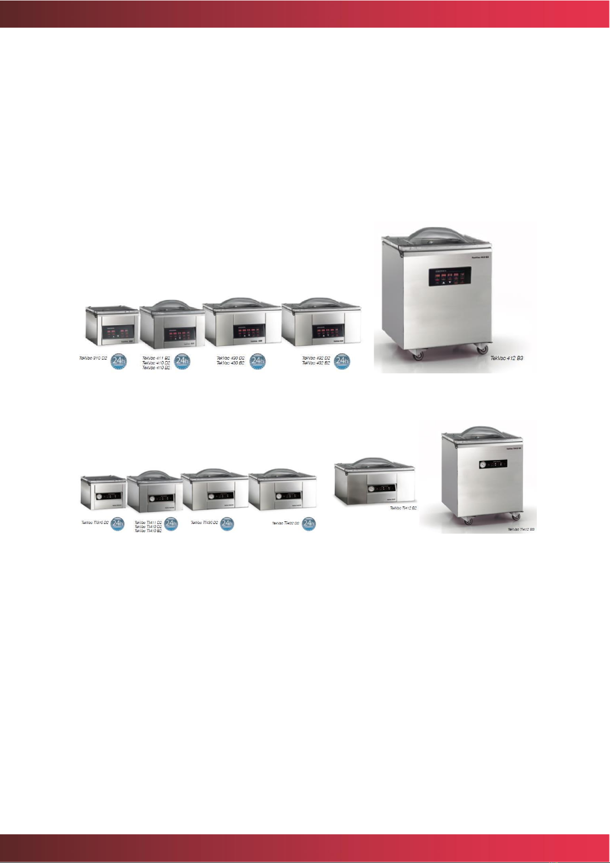
1.1. Vacuum packers models......................................................................................... 5
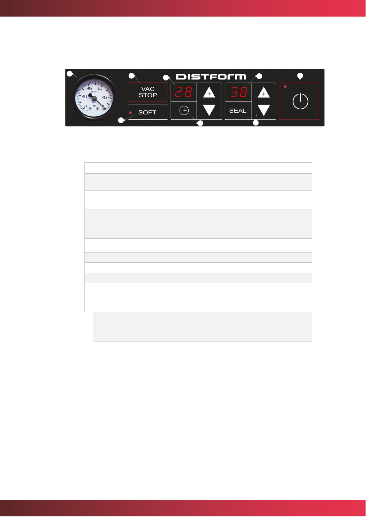
1.2. Keyboard (sensor).................................................................................................... 6
1.3. Keyboard (time)........................................................................................................ 8
1.4. Methodology............................................................................................................ 8
2. OPERATION ...................................................................................................9
2.1. Sensor models.......................................................................................................... 9
2.2. Time models............................................................................................................. 9
3. SOLUTION TO COMMON PROBLEMS ..........................................................11
3.1. Common problems ............................................................................................... 11
3.2. Automatic errors detection (only in sensor models).......................................... 11
3.2.1. Error E01....................................................................................................... 12
3.2.2. Error E02....................................................................................................... 12
3.2.3. Error E03....................................................................................................... 14
3.2.4. Error E04....................................................................................................... 15
3.2.5. Error E05....................................................................................................... 15
3.3. Vacuum pump ........................................................................................................ 16
4. DISASSEMBLE TO GET SERVICE ACCESS......................................................17
4.1. Frontal disassembly ............................................................................................... 17
4.2. Rear disassembly ................................................................................................... 20
4.3. Lid disassembly...................................................................................................... 21
4.4. Tub disassembly .................................................................................................... 22
5. TROUBLESHOOTING ....................................................................................24
5.1. Chech the power supplies .................................................................................... 24
5.1.1. Old model .................................................................................................... 24
5.1.2. Current model ............................................................................................. 26
5.2. Modo de test .......................................................................................................... 26
5.2.1. Electromechanical elements test............................................................... 27
5.2.2. Keyboard test............................................................................................... 30
5.2.3. Lid switch test............................................................................................... 31
5.2.4. Vacuum sensor test (sensor models only ) ............................................... 32
5.2.5. Internal memory test (sensor models only) .............................................. 32
6. BREAKDOWN REPAIRS ................................................................................33
6.1. Replacing lid switch ............................................................................................... 33

mychefcooking.com
TECHNICAL SUPPORT SERVICE MANUAL TEKVAC - DT.MS.TV.2103.2
3
6.2. Replacing the sealing profile................................................................................ 34
6.3. Replacing weatherstrip for the vacuum packer lid ............................................ 35
6.4. Replacing vacuum pump ...................................................................................... 36
6.5. Replacing power supply........................................................................................ 38
6.6. Replacing relay board ........................................................................................... 39
6.7. Replacing control board ....................................................................................... 39
6.8. Removing sealing transformer ............................................................................. 40
6.9. Replacing solenoid valve ...................................................................................... 41
6.10. Repairing vacuum sensor (sensor models)....................................................... 44
6.11. Reparing gas spring............................................................................................ 45
6.12. Repairing air inlet spigot .................................................................................... 48

mychefcooking.com
TECHNICAL SUPPORT SERVICE MANUAL TEKVAC - DT.MS.TV.2103.2
4
APPENDICES
APPENDIX 1. Wiring diagram (old model)........................................................50
APPENDIX 2. Wiring diagram (current model) .................................................51
APPENDIX 3. Relay assignation........................................................................52

mychefcooking.com
TECHNICAL SUPPORT SERVICE MANUAL TEKVAC - DT.MS.TV.2103.2
5
1. INTRODUCTION
1.1. Vacuum packer models
The following document has technical information to properly perform technical assistance
services (TS) on the TekVac vacuum packers. TekVac is designed for vacuum packing food
in plastic bags suitable for packaging.
TekVac packaging machines basically have two control panels. The panels by sensor and
the panels by time.
Figure 1. TekVac sensor vacuum packaging machines range
Figure 2. TekVac time vacuum packaging machines range

mychefcooking.com
TECHNICAL SUPPORT SERVICE MANUAL TEKVAC - DT.MS.TV.2103.2
6
The following image shows the main components of the vacuum packer.
Figure 3. Vacuum packaging machine components
1.2. Keyboard (sensor)
Figure 4. Keyboard description

mychefcooking.com
TECHNICAL SUPPORT SERVICE MANUAL TEKVAC - DT.MS.TV.2103.2
7
Function
Description
A
VAC Display
Indicates the vacuum level by %.
B
VAC+ Display
It is also used to indicate the number of machine hours, vacuum cycles
and errors which may occur.
C
GAS Display
Indicates the vacuum plus level in seconds.
D
SEAL Display
It is also used to indicate the number of machine hours and vacuum
cycles.
E
PROG Display
Indicates the gas level as a %. Only available in machines with gas.
F
VAC Button
Indicates the sealing time. It is also used to indicate the number of
machine hours, vacuum cycles or calibration of the machine.
G
VAC+ Button
Indicates the programme number.
H
GAS Button
Vacuum level selection button.
I
SEAL Button
Vacuum plus level selection button.
J
PROG Button
Gas level selection button. Only available in machines with gas.
K
VAC Indicator
Sealing time selection button.
L
VAC+ Indicator
Programme selection button.
M
GAS Indicator
Indicates the selection of the vacuum level.
N
SEAL Indicator
Indicates selection of the vacuum plus level.
O
PROG Indicator
Indicates the selection of the gas level. Only available in machines with
gas.
P
VACSTOP Button
Indicates sealing time selection.
Q
+ Button
Indicates programme selection.
R
- Button
Ends the vacuum cycle prematurely, stopping the engine and carrying
out the remaining cycles (gas injection, sealing, entry of air)
S
SOFT Button
Only acts when the vacuum level is greater than 50%.
T
ON/OFF Button
Increases the selected indicator value.
U
SOFT Indicator
If the machine is off by pressing along with the –Button, this allows
calibration to commence.
V
ON/OFF Indicator
Reduces the value of the selected indicator.
Table 1. Control panel indicators, displays and buttons

mychefcooking.com
TECHNICAL SUPPORT SERVICE MANUAL TEKVAC - DT.MS.TV.2103.2
8
1.3. Keyboard (time)
Figure 5. Control panel
Function
Description
A
Vacuum meter
Indicates the vacuum level between 0 y -1 bar. Maximum
vacuum level is -1 bar.
B
VACSTOP
button
Ends the vacuum cycle prematurely, stopping the motor and
doing the rest of the cycles (sealing, air injection).
C
SOFT button
Activates/deactivates the progressive air entrance. When the
mode is active, red led is on. To change the mode, keep the
SOFT button pushed at least two seconds.
D
Display TIME
Indicates vacuum time. Maximum 99 seconds.
E
"+ & -" button
Increases or decreases vacuum time value.
F
Display SEAL
Indicates sealing time. Maximum 9, 9 seconds.
G
"+ & -" button
Increases or decreases sealing time value
H
ON/OFF
button
Turns on or off the machine when it is pushed more than two
second. Also cuts a vacuum cycle when it is pressed less
than two seconds.
AUTO-CLEAN
OIL
With the vacuum packer turned off, press simultaneously
"SOFT" + "-" (vacuum time). It avoids possible moisture
leftovers that remain in the oil.
Table 2. Control panel functionality
1.4. Methodology
The technical assistance service will find in Solutions to common troubles, the most common
troubles and incorrect uses of the packer that can provoke malfunction, as well as the
possible solutions.
In case of failing the detection, the following chapters have information about accessing to
the zones that have to be checked (see Disassemble to get service access), how to locate
failures (see Troubleshooting) and how to repair them (see Breakdown repairs).
A
B
C
D
E
F
G
H

mychefcooking.com
TECHNICAL SUPPORT SERVICE MANUAL TEKVAC - DT.MS.TV.2103.2
9
2. OPERATION
2.1. Sensor models
First, we must set up the packing parameters, the next values: VAC (% of vacuum), VAC+
(extra time of vacuum), GAS (% of inert gas), SEAL (seal time) and SOFT (progressive
pressure recuperation). You can not select an extra vacuum level if the vacuum level is less
than 100%. Nor can select a vacuum level lower than 50%. Difference between the vacuum
level and the inert gas level must be upper than 50%.
After, for a correct packing you must put the packing bag correctly in the seal bar. Then you
must get down the lid.
At this point the engine starts and the display shows the% VAC real vacuum in the chamber.
After VAC process will start the VAC+ time. The VAC+ process will last many seconds are
shown in the VAC+ display.
If you choose the inert gas injection, the chamber is filled with it until it reaches the selected
gas percentage.
The seal consists of two phases: the first phase is the resistance heating; in this phase the
value of the display decreases progressively. The second phase (the duration is 5 seconds)
is the cooling of the bag. The value of the SEAL display increases progressively.
The last phase is the atmosphere recuperation. This can be done abruptly or by pulses
activating SOFT mode. This mode is useful for the bag to mold to the food. You can activate
de SOFT mode only before to start the vacuum process.
If you would abort the vacuum process press the VACSTOP button. This action cancels the
vacuum process, and the equipment will continue the next steps (inert gas inlet, seal, and
atmosphere air recuperation).
You can abort the vacuum cycle at any time. If you press the ON/OFF button the vacuum
packer cancels all process and recovers the atmosphere pressure.
We recommend rest periods between 3 minute cycles.
2.2. Time models
First, the packing parameters must be set up by adjusting the values VAC (time of vacuum),
SEAL (sealing time) and SOFT (progressive pressure recuperation).
After that, for a correct packing, the bag must be placed correctly in the sealing bar. Then,
get down the lid.
At this point, the pump starts running and the vacuum time display starts a countdown of
the adjusted time.
The vacuum process extracts air from inside the chamber so that the pressure decrease.
This process is monitored by the vacuum gauge placed on the control panel.

mychefcooking.com
TECHNICAL SUPPORT SERVICE MANUAL TEKVAC - DT.MS.TV.2103.2
10
The sealing process has two steps: the first step is the resistance heating; in this phase the
value of the display decreases progressively. The second phase (which duration is 5
seconds) is a cooling down of the heating element. The value of the SEAL display increases
progressively.
The last phase is the atmosphere recuperation. This can be done abruptly or by pulses
activating SOFT mode. This mode is useful for the bag to mold to the food. You can activate
de SOFT mode only before to start the vacuum process.
The vacuum process can be aborted by pressing the VACSTOP button. This action cancels
the vacuum process, and the equipment will continue the next steps (seal and atmosphere
air recuperation).
You can abort the vacuum cycle at any time. If you press the ON/OFF button the vacuum
packer cancels all process and recovers the atmosphere pressure.
3 minutes resting periods between cycles are recommended.

mychefcooking.com
TECHNICAL SUPPORT SERVICE MANUAL TEKVAC - DT.MS.TV.2103.2
11
3. SOLUTION TO COMMON PROBLEMS
3.1. Common problems
Description
Solution
The vacuum packer does not turn on
Check the connection wire to be correctly plugged.
Press more than three seconds the ON/OFF button.
The vacuum packer does not reach 100%
vacuum
Perform a machine calibration (sensor models).
Check that the sealing silicone (on the cap) is
correctly fitted.
Check the entire vacuum circuit.
The vacuum packer does not seal
Check the sealing bar to be correctly placed in both
elevator shafts and that there is not any food leftover
that blocks the electric current flow.
The vacuum packer does not seal
properly
Change the sealing time of the bag.
Faulty cover detector (switch). Make change.
Faulty lid detector (switch). Make change.
Table 3. Common problems
3.2. Automatic errors detection (only in sensor models)
The device has algorithms that detect irregular situations which can lead to a malfunction of
the system. These situations are notified to the user via an error screen like the shown down
below:
Figure 6. Error screen

mychefcooking.com
TECHNICAL SUPPORT SERVICE MANUAL TEKVAC - DT.MS.TV.2103.2
12
The following table shows the possible errors and their solution:
Error
Description
Solution
E01
Lid down
Open the lid. If the error persists, call the technical service, and
present the error code.
E02
Vacuum system
failure
System has detected the motor had been working too much time
to reach certain level of vacuum. Calibrate the system. If the
calibration is performed properly, redo the process.
If not, call the technical service.
E03
Vacuum sensor
failure (minimum)
Check the vacuum sensor connection tube trying to find out if it
has leaks or a bad connection. If it all seems to be correct, call the
technical service presenting the error code and the value that
VAC indicator was giving right before the error.
E04
Vacuum sensor
failure (maximum)
Check the vacuum sensor connection tube trying to find out if it
has leaks or a bad connection. If it all seems to be correct, call the
technical service presenting the error code and the value that
VAC+ indicator was giving right before the error.
E05
Internal error
Control board has detected an internal error. Call the technical
service and expose the error code
Table 4. Errors and possible solutions
3.2.1. Error E01
Error E01 comes from the detection of the incorrect position of the lid. That can be due to:
- Deterioration of the lid switch
- Deterioration of the switch wiring
- Deterioration of the relay board
- Deterioration of the ribbon cable connecting the relay board and control board
- Deterioration of the control board
In front of that situation, it is recommended to go into Test Mode (see chapter 5.2) and
perform the lid switch test (see 5.2.3) changing one by one the elements listed before.
3.2.2. Error E02
The system has detected that the vacuum bomb had worked too much time to reach a
certain vacuum level. This may be due to:
- Atmospheric pressure change
- Deterioration of the pressure sensor
- Contamination of the oil
- Leaks on the vacuum circuit
- Deterioration of the vacuum pump

mychefcooking.com
TECHNICAL SUPPORT SERVICE MANUAL TEKVAC - DT.MS.TV.2103.2
13
Calibration
Before the first use and when installing a packaging machine, it is necessary to perform a
calibration of the equipment (only for sensor packaging machines), to adjust it to the local
atmospheric pressure where it will be used.
To enter calibration mode, with the appliance off and the lid open, press the “+” and “–”
buttons simultaneously. A screen will appear immediately like the one shown below.
Figure 7. Initial calibration screen
Once in this status, lower the lid to automatically begin the calibration process. If you do not
wish to calibrate, exit this status by pressing the ON/OFF button. The calibration process
will last for around one minute and the VAC and VAC+ displays will show the minimum and
maximum values provided by the vacuum sensor.
For normal atmospheric pressures, the minimum value will vary between 50 and 70, while
the maximum value will vary between 400 and 650.
Figure 8. Calibration process
Upon finishing calibration, the appliance shows the number of completed hours and
vacuum cycles.

mychefcooking.com
TECHNICAL SUPPORT SERVICE MANUAL TEKVAC - DT.MS.TV.2103.2
14
Sensor test
You should do the tests specified in Error E03 (see chapter 3.2.3) and Error E04 (see chapter
3.2.4).
Oil change
If any of the previous steps have solved the problem, do an oil change of the motor.
Afterwards redo the sensor calibration (see chapter 3.2.2.1).
Leaks in the vacuum circuit
There is not an effective way to check the vacuum circuit. To be able to check it, it is
necessary to test one by one all the parts, starting at the vacuum bomb and moving on,
mounting and dismounting all the components. Habitually, a union of fine Teflon fittings
should not leak, so the most critical zones where the leaks can occur are:
- Weatherstrip. The union between ends in the rear part has not been done properly,
so there are gaps between them.
- Motor-tub aspiration tube. It has some holes.
- Solenoid valves.
oSolenoid valves have orientation (see chapter 6.9), so assembling them
wrongly can lead to leaking.
oSome dirtiness has been deposited in solenoid valves joints; therefore, it
does not close completely.
- Vacuum circuit (pipes, etc.). Possible pores in pipes, bad connections of the pipes
into fittings, etc.
A possible way to detect leaks in the circuit could be the usage of a flame. The method to
check the system with this mode is doing the maximum vacuum possible with the packer
and before it starts to restore the ambient pressure, unplug it. With all the registers
removed, proceed to pass the flame though the vacuum circuit. The fact that a leak exists
will make the flame to move in the direction of the leak. If this method is used, be careful to
do not burn any component.
3.2.3. Error E03
Check the sensor by doing the process explained in section 5.2.4.
With the lid open, the VAC indicator should show a value between 50 and 70. If the value is
0, probably any of the vacuum sensor feet are broken. In some cases, it can be solved
following the steps explained in vacuum sensor reparation (see chapter 6.10).
If it is not the case, the control board will have to be changed (see Replacing control board).

mychefcooking.com
TECHNICAL SUPPORT SERVICE MANUAL TEKVAC - DT.MS.TV.2103.2
15
3.2.4. Error E04
Check the sensor by doing the process explained in Vacuum sensor test (see chapter 5.2.4).
With lid closed, start the engine pressing the VAC button for 120 seconds. The VAC
indicator should go up gradually to show a value between 400 and 650. If the value is close,
or it starts descending at the rate of several counts per second, probably there are leaks in
the vacuum circuit.
If it does not reach the value expected, change the control board (see Replacing control
board).
3.2.5. Error E05
Control board performs internal tests continuously. If any of them fails, some component of
the board is malfunctioning.
Change the control board (see Replacing control board).

mychefcooking.com
TECHNICAL SUPPORT SERVICE MANUAL TEKVAC - DT.MS.TV.2103.2
16
3.3. Vacuum pump
The following table shows the main defects that can have the rotary vane pumps, as well as
the possible solutions:
Defect detected
Cause
Solution
The pump rotates with difficulty
or generates considerable noise
Too much oil
Take out the leftover oil
Wrong type of oil
Use approved oil
Power consumption too high
Ambient temperature too low
If the ambient temperature
gets lower than 5ºC use SAE-20
DIN51506 oil.
Pump has been stopped too
much time
Run the pump with the
aspiration intake closed, until it
warms up.
The pump oil has not been
changed for a long time
Change the oil and run the
device for 15 mins. Change the
oil again.
Escape filter is obstructed
Change the filter.
Wrong vacuum
Lubricating oil is missing
Refill with approved oil up to
the recommended level.
Obturated filter
Replace filter.
Aspiration flow below the
normal values
Aspiration sieve obturated
Disassemble the suction block
and clean the sieve.
Leaks in the suction pipe
Obture the leak and replace
the pipe if it is necessary.
Pump oil leakage in the
escape. Presence of oil
mist.
Escape filter obturated, so it
generates overpressure.
Replace filters and their toric
joins if they are damaged.
If it happens after refilling the
oil, it is because the filters are
accidentally wet of oil.
Run the pump with half
aspiration tube open.
Usage of non-approved oil
Empty and refill with approved
oil.
Pump is blocked and the engine
does not have enough torque to
move it.
Pump has worked without oil
Contact with the repair facility
or Mychef.
Rotor vanes are blocked due
to a presence of a strange
object.
Retention valve of the intake
port blocked
Lubricating oil
has colour
Black
It has not been replaced with
the appropriate frequency or it
is not approved
In any case, remove the oil, refill
with approved oil, and rotate
the pump for 10 cycles.
Milky
Pump has sucked water
Viscosity too
high or too
low
Unsuitable oil used
Table 5. Defects and solutions of vacuum pump

mychefcooking.com
TECHNICAL SUPPORT SERVICE MANUAL TEKVAC - DT.MS.TV.2103.2
17
4. DISASSEMBLE TO GET SERVICE ACCESS
Caution: Before doing any disassemble, you must be sure that the device is
unplugged from the electric network.
4.1. Frontal disassembly
The following picture shows how to disassemble the frontal of the vacuum packers.
Figure 9. Frontal disassembly (Step 1)
Step 1 →Unscrew the bolts with Allen head placed at the bottom part.
1
2
3

mychefcooking.com
TECHNICAL SUPPORT SERVICE MANUAL TEKVAC - DT.MS.TV.2103.2
18
Figure 10. Frontal disassembly (Step 1) Current model
Step 2 →Push the bottom part of the frontal to the interior of the vacuum packer (old
model).
Figure 11. Frontal disassembly (Step 2)
Step 3 →Move down the frontal, thus the locking teeth become free.
Figure 12. Frontal disassembly (Step 3)
Locking teeth.

mychefcooking.com
TECHNICAL SUPPORT SERVICE MANUAL TEKVAC - DT.MS.TV.2103.2
19
Once these steps are done, the frontal becomes unlocked.
Figure 13. Unlocked frontal
Be careful not to stretch the frontal since the pipe of the vacuum sensor and
the connection cable of the control are connected. To completely extract the
frontal, pipe and plane wire must be removed.
To reassemble the board, follow the steps in the reverse order.
1 →Place the vacuum sensor pipe and the flat cable.
2 →With the inferior part of the frontal introduced into the packer, properly set the locking
teeth.
3 →Picking the frontal by the bottom bringing it back, moving it to the appropriate position.
Be careful since the frontal has 2 riveted nuts used to fix it with bolts. These nuts have to be
above the lateral plate, as it is shown in the following picture (old model).
Figure 14. Fixing screws for the frontal

mychefcooking.com
TECHNICAL SUPPORT SERVICE MANUAL TEKVAC - DT.MS.TV.2103.2
20
In the current model, the nuts are located on the sides, so the front flange is at the bottom,
making it easier to assemble.
Finally screw the two screws.
4.2. Rear disassembly
To disassemble the rear part, follow the steps down below:
Step 1 →Unscrew the two bolts.
Figure 15. Rear disassembly (Step 1)
Step 2 →Take it out avoiding the external vacuum connector and the connection pin of
inert gas.
Figure 16. Rear disassembly (Step 2)
Table of contents