Myray hyperion X5 User manual

hyperion X5 - technical manual
Cod. 97070183
Rev. 00 05/2015 www.my-ray.com
EN


EN
TECHNICAL MANUAL
hyperion X5
Code Rev Date
97071183 00 15.05


TECHNICAL MANUAL - hyperion X5
EN PC CONFIGURATION 3
1.PC CONFIGURATION ................................................................................................................................... 5
1.1.SYSTEM REQUIREMENTS ...................................................................................................................... 5
1.2.SETTING UP THE DEVICE ...................................................................................................................... 6
1.2.1.PRELIMINARY OPERATIONS ........................................................................................................... 6
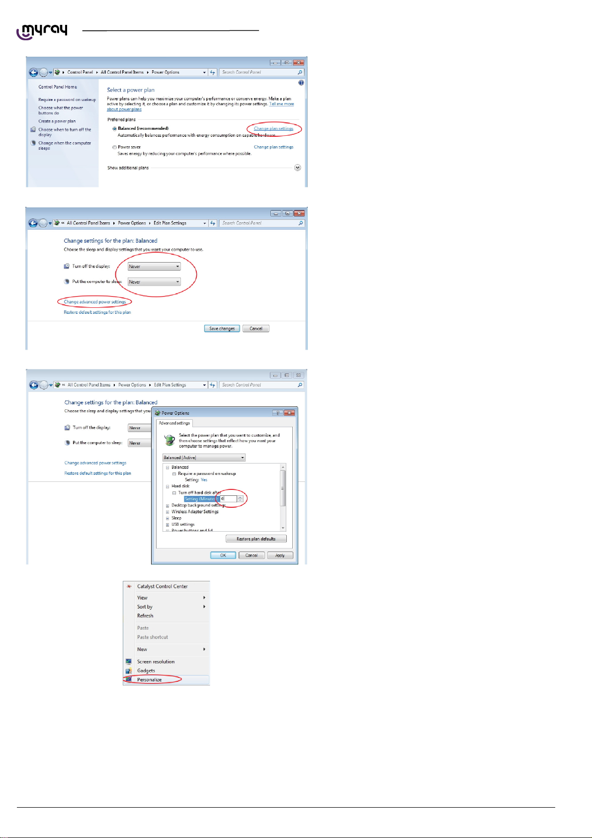
1.2.2.OPERATING SYSTEM SETTINGS .................................................................................................... 6
1.2.3.DISABLING WINDOWS FIREWALL ................................................................................................... 9
1.2.4.INTEL PRO 1000” NETWORK CARD INSTALLATION .................................................................... 10
1.2.5.ACQUISITION SERVER” SOFTWARE INSTALLATION .................................................................. 12
1.3.CONNECTION AND CONFIGURATION ................................................................................................ 17
1.3.1.SOFTWARE ACQUISITION SERVER .............................................................................................. 17
1.3.2.IRYS INSTALLATION AND CONFIGURATION................................................................................ 22
2.CALIBRATION ............................................................................................................................................. 28
2.1.PRELIMINARY OPERATIONS ............................................................................................................... 28
2.2.DEVICE CONFIGURATION .................................................................................................................... 29
2.3.XRAY ALIGNMENT ................................................................................................................................. 30
2.4.VERIFYING THE SENSOR CALIBRATION ............................................................................................ 34
2.5.VERIFYING THE MECHANICAL CENTERING ...................................................................................... 35
2.6.TEST LASER ........................................................................................................................................... 37
2.7.CALIBRATION DATA BACKUP .............................................................................................................. 40
3.CONTROL BOARDS DESCRIPTION .......................................................................................................... 41
3.1.UNIT BLOCK DIAGRAM ......................................................................................................................... 41
3.2.POWER BOARD 97661407 .................................................................................................................... 42
3.2.1.CONNECTORS LIST ........................................................................................................................ 44
3.2.2.FUSES AND DIP SWITCHES LIST .................................................................................................. 4 4
3.2.3.LEDS LIST ......................................................................................................................................... 44
3.3.LOGIC BOARD 97661408 ....................................................................................................................... 46
3.3.1.CONNECTORS LIST ........................................................................................................................ 48
3.3.2.DIP SWITCHES LIST ........................................................................................................................ 48
3.3.3.LEDS LIST ......................................................................................................................................... 48
3.4.SENSOR INTERFACE BOARD 97661485 ............................................................................................. 50
3.4.1.CONNECTORS LIST ........................................................................................................................ 52
3.4.2.LEDS LIST ......................................................................................................................................... 52
3.5.KEYBOARD BOARD 97661484 .............................................................................................................. 52
3.5.1.CONNECTORS LIST ........................................................................................................................ 52
3.6.LOGO BOARD 97661539 ....................................................................................................................... 52
3.6.1.CONNECTORS LIST ........................................................................................................................ 52


TECHNICAL MANUAL - hyperion X5
EN PC CONFIGURATION 5
1. PC CONFIGURATION
1.1. SYSTEM REQUIREMENTS
hyperion X5 needs two ethernet connections, one for generic communication purposes (this supports DHCP and can be
set up through the local network) and a second dedicate connection, which must set up as direct point-to-point between
the unit and the INTEL PRO 1000 network card on the PC.
The PC dedicate to image aquisition (from now on referred to as “Acquisistion server”) must respect the following system
specification. Such a PC can be purchased as an option directly from Cefla, the model is Lenovo ThinkCentre Edge 73
Tower.
System requirements:
PROCESSOR Intel H81, Intel Core i3 4150 (3.5GHz, 3MB L3 Cache, 1600MHz), Quad core
RAM 4GB
HD 500GB / 7200 rpm
DVD DVD+-RW DL
NETWORK 1 Eth Giga integrated + 1Intel(R) Gigabit CT Desktop Adapter PCI-e
O.S. WIN7 Pro 64bit
VIDEO CARD
A
MD Radeon HD 7450 PCI Express 2.0, 128 Bit, 1024 MB, DDR3
POWER SUPPLY 500W
Besides the configuration above also the following ones have been validated and tested as “Acquisition Server” for X5:
COMPONENT CONFIG 1 CONFIG 2 CONFIG 3 CONFIG 4
PROCESSOR 1 CPU INTEL XEON
E5-2630 - 2,3GHZ -
6 CORE
1 CPU INTEL I7 3770
- 3,4 GHZ – 4 CORE
1 CPU INTEL XEON
E5-1620 - 3.60 GHz -
4 CORE
1 CPU INTEL XEON
E3-1270 V3 – 3.50
GHz – 4 CORE
POWER SUPPLY >= 800 W >= 550 W >= 600 W >= 400 W
VIDEO CARD ATI RADEON HD 7770 OC GHZ EDIT. VAPORX 1GB GDDR5 ATI RADEON R7
250 1GB
HARD DISK 2 SATA HDD - 300
GB - 10K RPM
1 SATA HDD - 500 GB - 10K RPM
RAM 4 GB DDR3 8 GB DDR3 1600 MHZ
O.S. WINDOWS 7 PROFESSIONAL 64 BIT SP1
NETWORK 2 ETHERNET CARDS (AT LEAST ONE INTEL PRO -1000 )
OTHER MINIMUM SCREEN RESOLUTION 1280X1024, 64 MILLION COLORS
DVD+-RW DL
The following video cards have been tested and validated for use with hyperion X5:
VIDEO CARDS MINIMUM POWER SUPPLY
A
TI Radeon HD 4850 / 5770 – 1GB >= 450 W
A
TI Radeon HD 4870 / 4890 / 5850 / 5870 – 1GB >= 500 W
Sapphire Radeon HD 6750 / 6770 – VaporX – 1GB –
RAM GDDR5
>= 450 W
Sapphire Radeon HD 6850 / 6870 / 6950 / 7870 – VaporX
– 1GB – RAM GDDR5
>= 500 W
Sapphire Radeon HD 7770 – GHz Ed. - OC - VaporX –
1GB – RAM GDDR5
>= 500 W
Sapphire Radeon HD 6970 – VaporX – 2GB – RAM
GDDR5
>= 550 W
Sapphire Radeon HD 7850 - 1GB / 2GB - RAM GDDR5 >= 500 W
Sapphire Radeon HD 7870 - 2GB - RAM GDDR5 >= 500 W
Sapphire Radeon HD 7750 - OC - 1GB – RAM GDDR5 >= 400 W
A
MD FirePro W7000 – 4GB GDDR5 >= 400 W
A
MD/Sapphire Radeon R7 250 1GB – RAM GDDR5 >= 400 W
A
MD/Sapphire Radeon R7 260X - RAM 1GB DDR5 >= 500 W
A
MD/Sapphire Radeon R9 270 - RAM 2GB DDR5 >= 500 W

TECHNICAL MANUAL - hyperion X5
6
PC CONFIGURATION EN
1.2. SETTING UP THE DEVICE
1.2.1. PRELIMINARY OPERATIONS
The acquisition server must comply to the system requirements detailed above. If provided from Cefla, the complete
software comes preinstalled, otherwise it will be strictly mandatory to choose a compliant PC and install the software
correctly.
The 2 network adapters on the acquisistion server are needed for communication with the hyperion X5.
One of these network adapters is used for a direct connection with the image detector on the X5.
If the acquisition server is not purchased from Cefla, the network adapter will be provided in the accessories box of the
hyperion X5 and will need to be installed and configured on site.
The dedicated network adapter is an Intel Pro 1000 and will need a free PCI-E slot on the motherboard of the acquisition
server to be installed.
The only supported operating system for the acquisition server is WINDOWS 7 PRO 64 bit. The Intel Pro 1000 will be
automatically recognized by the operating system and drivers will be installed automatically.
The acquisition server must be accessed with an Administrator level user account.
IMPORTANT: for up to date video card drivers please refer to Cefla's extranet website.
The Microsoft .NET Framework 4.0 are required for the software to work and will be installed together with the video
card drivers.
Please make sure that the following entries are present in the installed programs list:
If the libraries were not installed automatically, please download them from the Microsoft website and install them
manually.
1.2.2. OPERATING SYSTEM SETTINGS
”.
Open the Control Panel , select “User
Account”and then “Change User Account Control
Settings”.

TECHNICAL MANUAL - hyperion X5
EN PC CONFIGURATION 7
Select the lowest notification level “Never Notify”.
RESTART THE PC.
From the Control Panel select “Power Options”.

TECHNICAL MANUAL - hyperion X5
8
PC CONFIGURATION EN
On the “Balanced”profile select “Change plan
settings”.
Set“Turn OFF display”and“Put the computer to
sleep”to“Never”. Select “Change advanced power
settings”.
Set“Hard disk Turn OFF hard disk after 0”.
A
lso deactivate any screensaver. To do this right
click on the mouse on any icon-free desktop or
window area and select “Personalize” from the
menu.

TECHNICAL MANUAL - hyperion X5
EN PC CONFIGURATION 9
A
lso deactivate any screensaver. To do this right
click on the mouse on any icon-free desktop or
window area and select “Personalize” from the
menu.
1.2.3. DISABLING WINDOWS FIREWALL
From the Control Panel select “Administrative
Tools” and double click on “Services”:

TECHNICAL MANUAL - hyperion X5
10 PC CONFIGURATION EN
Scroll down the service list, right click on the
“Windows firewall” service and double click.
Go to the “Startup type” drop-down menu and
select “Disabled”. Then press the “Stop” key to
stop the service currently being executed.
Wait until the service is stopped:
Click on “OK” to close the dialogue window.
From the Windows Services list, search for “Windows update”, stop the service and disable the automatic startup.
1.2.4. INTEL PRO 1000” NETWORK CARD INSTALLATION
Right click with the mouse on “Computer”, select
“Properties” and select “Device Manager” in the
left column.

TECHNICAL MANUAL - hyperion X5
EN PC CONFIGURATION 11
Expand the “Newtork Adapter” group, right click
on the “Intel pro 1000”, and select “Properties”.
Select the “Advanced” tab, highlight the “Jumbo
Packet”, and set it to “9014 byte

TECHNICAL MANUAL - hyperion X5
12 PC CONFIGURATION EN
From the “Advanced” tab set the “Receive Buffers”
parameter to 2048
WARNING: the “Receive Buffers” parameter migh not show on this window. If not visible, please search
for the “Performance options” parameter, click on “Properties” and set the “Receive bufffers” value from
there.
1.2.5. ACQUISITION SERVER” SOFTWARE INSTALLATION
This software can only be installed on 64 bit
Operating Systems.
Launch the software installer (from the setup
menu on the usb dongle or from Extranet
download)and select the language:
Click on “Next”

TECHNICAL MANUAL - hyperion X5
EN PC CONFIGURATION 13
Select “I accept” , then click “Next”
Click on “Install”
Wait

TECHNICAL MANUAL - hyperion X5
14 PC CONFIGURATION EN
Installed software will be checked, any missing
system component will be installed at this stage.
The Pleora driver for the Intel Pro 1000 network
adapter will be installed automatically, click “Next”
A
ccept and click “Next”

TECHNICAL MANUAL - hyperion X5
EN PC CONFIGURATION 15
Click on “Install”
Wait for the driver installation to finish.
If the following window is displayed, select
“Always Trust” and click “Install”

TECHNICAL MANUAL - hyperion X5
16 PC CONFIGURATION EN
Click “Finish” at the end of the installation.
Restart the PC
The “Acquisition server” software will start up
automatically and will be accessible from the
system tray.

TECHNICAL MANUAL - hyperion X5
EN PC CONFIGURATION 17
1.3. CONNECTION AND CONFIGURATION
1.3.1. SOFTWARE ACQUISITION SERVER
hyperion X5 can be connected to a LAN or direclty to the Acquisistion server PC. Either way, the image detector must be
connected directly with a point-to- point connection to the Acquisition Server PC.
The direct connection between the image detector and the PC is managed automatically by the software, there is thus no
need to set the IP address on the detector for the connection to be estabilished. The Intel Pro 1000 always stays
configured as from system default (DHCP) and the connection is managed automatically.
It could be necessary to set up a static IP address for the network adapter used for the PC to hyperion X5 system
communication. If this network adapter is directly connected to the unit, the IP address for the PC should be set to one in
the same subnet as the hyperion X5's default (e.g.192.168.1.150)
To set a static IP address on a network board it is
necessary to click on the Start button, type
“ncpa.cpl” and press Enter. The Network
connection window will open:
If it is necessary to give the communication
network board a fixed IP address , right-click with
the mouse on the relative connection (not the
INTEL pro 1000 one, the one supplied by the
other network board) and select “Proprieties”.

TECHNICAL MANUAL - hyperion X5
18 PC CONFIGURATION EN
Select “Protocol internet version 4
(TCP/IPv4)”and click on “Properties”.
Specify an IP address compatible with the one of
the X9. In the “IP Address” field, type an address
as 192.168.1.XXX where XXX can be a digit
included between 1 to 254, with the exception of
the X9 default IP (usually 160). The Subnet mask
will be automatically filled.
Confirm by pressing the “OK” button.
If the unit is connected to a LAN with DHCPC (as in the following diagram) then the noetwork adapter should be set to
“Obtain IP address automatically”. The DHCP server will assign correct IP addresses to both the hyperion X5 and the
acquisistion server.
Table of contents
Other Myray Medical Equipment manuals
Popular Medical Equipment manuals by other brands

Mackworth
Mackworth Hazel Classic Universal user manual

Gardigo
Gardigo 26104 instruction manual

Fonda
Fonda LEDDLES user manual

OpeMed
OpeMed Nursing Bench 3000 owner's manual

Air Techniques
Air Techniques MOJAVE LT3M User and installation manual

Enraf Nonius
Enraf Nonius Endomed 581 ID operating instructions

Thayer Medical Corporation
Thayer Medical Corporation Quake Instructions for use

Novis
Novis Molift RAISER PRO Use guide

Gima
Gima 28202 manual

Arjo
Arjo Tornado Assembly and installation instructions

DT Research
DT Research 362MD Basic operation guide

AffloVest
AffloVest RP8300 Instructions for Use and Owner's Manual