Myray hyperion X9 User manual

M a n u a l e t e c n i c o
c o d . 9 7 0 7 1 1 4 3 r e v . 0 1
hyperion X9
A f t e r S a l e s S e r v i c e - P l a n t V i a B i c o c c a 1 4 / c 4 0 0 2 6 I m o l a ( B O )
I t a l y - T e l . + 3 9 0 5 4 2 6 5 3 7 4 2 - F a x + 3 9 0 5 4 2 65 359 6
E - m a i l : s e r v i c e . m y r a y @ c e a . i t
Stabilimento / Plant
Via Bicocca 14/c - 40026 Imola (Bo) Italy
Tel. (+39) 0542 653441 - Fax (+39) 0542 653555
Www.ceadentale.it - ceadentale@cea.it
A f t e r S a l e s S e r v i c e - P l a n t V i a B i c o c c a 1 4 / c 4 0 0 2 6 I m o l a ( B O )
I t a l y - T e l . + + 3 9 0 5 4 2 6 5 3 4 4 1 - F a x + + 3 9 0 5 4 2 6 5 3 5 9 6
E - m a i l : s e r v i c e . c e a d e n t a l e @ c e a . i t
Stabilimento / Plant
Via Bicocca 14/c - 40026 Imola (Bo) Italy
Tel. (+39) 0542 653441 - Fax (+39) 0542 653555
Www.ceadentale.it - ceadentale@cea.it
T e c h n i c a l m a n u a l
c o d . 9 7 0 7 1 1 4 3 r e v . 0 1
hyperion X9


1
EN hyperion - TECHNICAL MANUAL
CONTENTS
0. Assembly instructions ...................................................................................................................................................... 3
0.0 Removal of packaging................................................................................................................................................. 3
0.1 Transport with fork-lift (COD. 96600536) .................................................................................................................... 4
0.2 Transport with handles (COD 96600540)................................................................................................................... 8
0.3 Wall mounting.............................................................................................................................................................. 8
0.4 Supportbaseoormountinginstructions .................................................................................................................... 8
0.5 Patient arm installation ................................................................................................................................................ 9
0.6 Electrical connections on the PFC board ................................................................................................................. 16
0.7 CBCT panel installation ............................................................................................................................................. 17
0.8 Ethernet connections and X-ray emission key........................................................................................................... 19
0.9 Installing the cephalometry arm................................................................................................................................. 21

2EN
hyperion - TECHNICAL MANUAL

3
EN hyperion - TECHNICAL MANUAL
0. Assembly instructions
InstallationoftheX-rayunitmustbedonebyqualiedtechniciansinaccordancewiththemechanicalandelectrical
assemblyinstructionsdenedasfollows.Checkthatthevoltageindicatedonthesysteminfoplatecorrespondstothat
of the electrical system.
0.0 Removal of packaging
The device must be transported packaged as far as the characteristics of the building will allow. Remove the cardboard
packaging outside the area/room where the device will be installed.

4EN
hyperion - TECHNICAL MANUAL
0.1 Transport with fork-lift (COD. 96600536)
Open the package and take out the box that contains the covers and box. Cut the two straps that secure hyperion to
the wooden pallet. Screw on the feet (if the apparatus is installed without the base); secure the hand truck’s brackets
(A) to the base of the x-ray unit with the screws provided.
Mount the brackets on the base of hyperion screwing them onto the metal support.
The brackets are to be secured by screwing two bolts in holes “B”. The feet or bolts for securing the additional mounting
plate can be placed in holes “C”. In this case, slots C” allow the bracket to be correctly installed with the bolts of the
plate still in place.

5
EN hyperion - TECHNICAL MANUAL
Remember to place the slide’s brackets on top of the post’s metal base. If they are mounted under the base, theY will
bebetweenthepostandoor,makingitimpossibletoremovethemoncetheslideislowered.
Lift the panoramic unit so that it is vertical, mount the two crossbars with wheels (B) and loosen the screws (C) to raise
hyperion’s base so that the slide is able to move. Be extremely careful when moving the equipment.
Thecrossbarswithwheelsnearthepostcanbeinstalledintwopositions:inthefrontorbackofthepost.Thegures
below illustrate the two positions of the holes and crossbar correctly installed.
Crossbar installed in the front
Crossbar installed in the back

6EN
hyperion - TECHNICAL MANUAL
Once hyperion has been put in place for installation, lower the slide by loosening the four screws that connect the
brackets to the wheels.
Intheunitisinstalledonaplate,securethexingscrewstothelatterbeforelooseningtheslidecompletely.
Iftheunitiswall-mounted,securehyperion’sposttothewallasshowninthefollowinggure.
Loosentheslideonlyaftertheposthasbeenrmlyattachedtothesupport.
Position Code Name Quantity
1 99932078 MOBILE POST (MACHINED) 1
2 99932130 PIN FOR WALL-MOUNTING
2
3 52220045 FLANGED M12 NUT FOR WALL BRACKET
4 52220011 MEDIUM NUT UNI 5588 M12
5 53135024 CONVEX WASHER M12 4
6 53135025 CONCAVE WASHER M12
7 99932076 WALL BRACKET 1
Before going on to the next installation steps, remember to remove the safety screw that blocks the head assembly.
The screw is found at the top of the head assembly.

7
EN hyperion - TECHNICAL MANUAL

8EN
hyperion - TECHNICAL MANUAL
0.2 Transport with handles (COD 96600540)
As an alternative to the fork-lift the device can be transported using the handles that, as shown in the diagram, can be
xedinthreedifferentpositions.
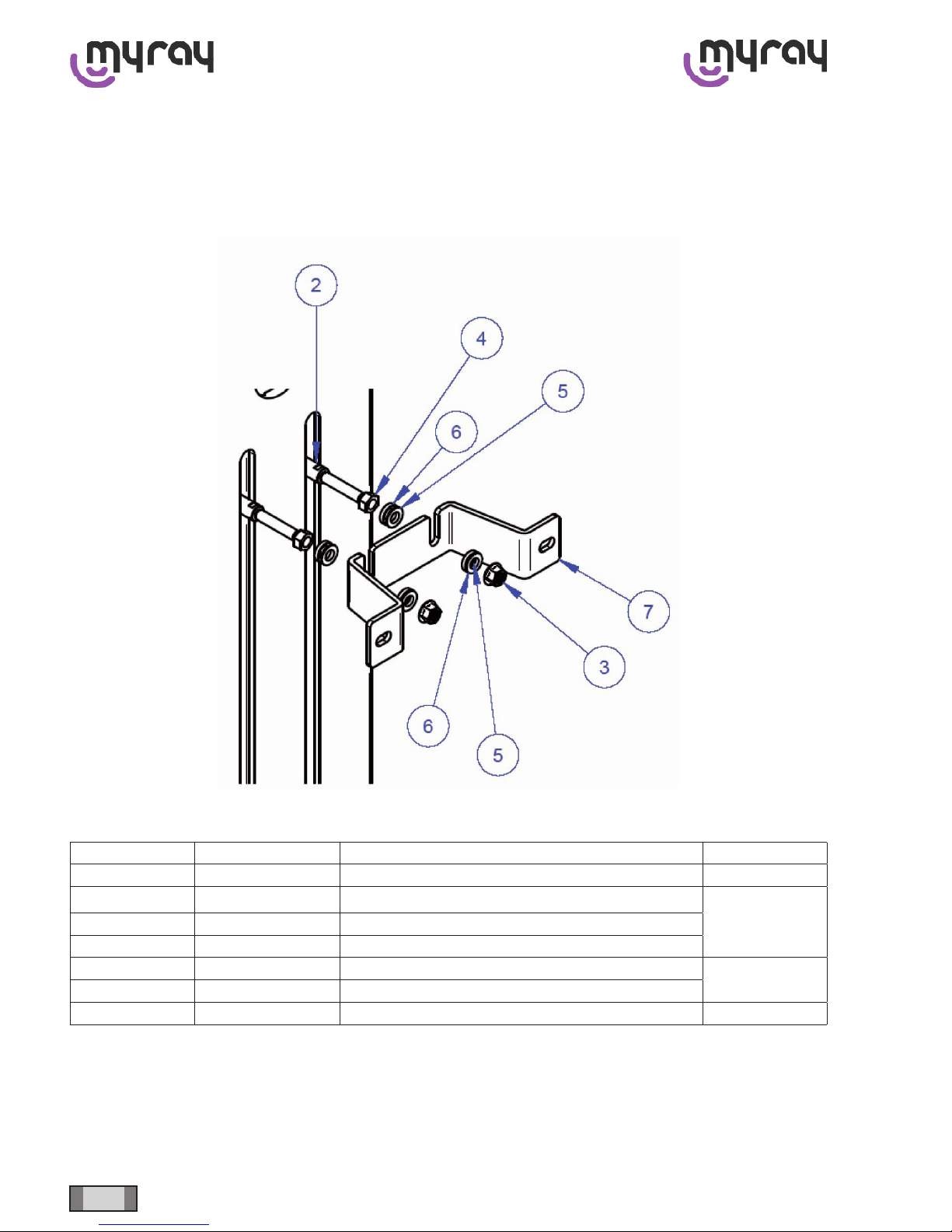
0.3 Wall mounting
-Fit the attachment bracket onto the wall;
- Important: before lifting the device vertically remember to install the support feet at the base of the column. Bring
the device up against the wall, place it on its feet and attach it, without tightening, to the bracket with the supplied
semi-spherical washers and nuts;
-Remove the fork-lift;
-Check for proper levelling with a spirit level and if necessary adjust the feet;
-Complete attachment of the bracket;
-Itisadvisabletodrillholesintheooratthepointsoftheserviceholesontheplateandxthebasetotheoor
using 2 expansion screws.
0.4 Support base oor mounting instructions
-With the aid of a fork-lift, position the device above the support base; remove the feet and lower the device in line
withthexingholes;
-Fix the device to the support base using the four supplied bolts;
-Remove the fork-lift;
-Check for proper levelling with a spirit level and if necessary adjust the feet;
-Itisadvisabletodrillholesintheooratthepointsoftheserviceholesontheplateandxthebasetotheoor
using 2 expansion screws.

9
EN hyperion - TECHNICAL MANUAL
0.5 Patient arm installation
Oncetheunitisxedtothebaseplateortothewall,itisnecessarytoinstallthepatientarm.
Before proceeding with the installation, prepare the cables for the column passage by tying them one to each other,
using scotch tape and aligning them in order to reduce as much as possible their dimension.
WARNING: do not use the handles on the console side to lift and move the arm during the installation procedure.
Always grab the arm by the metal frame.

10 EN
hyperion - TECHNICAL MANUAL
Before moving the arm towards the support shelf, pay attention and place the cables in the apposite slot (A), in order
to not damage them during the installation

11
EN hyperion - TECHNICAL MANUAL
Pass the cables in the apposite hole next to the shelf and push them to the upper edge of the column.
The arm must be aligned cautiously to the shelf on the column side. Inside the arm there are two cylindrical pins that
are going to match the holes highlighted here below once the arm is correctly aligned.
WARNING:thepinscannotcarrytheweightofthearm,soitisnecessarytomanuallyholdthearmuntilitisxedwith
the appropriate screws.

12 EN
hyperion - TECHNICAL MANUAL
Fix the arm to the column using the provided screws.
WARNING: the holes matching the screws slots are highlighted in the following images (B for the alignment pins, C
for the screws).

13
EN hyperion - TECHNICAL MANUAL
Oncethearmisxed,connectthetwo-wirecable(white-brown)tothecorrespondingcablefoundontheupperpartof
the column (see picture); this cable is connected to the emergency stop button placed below the patient arm.

14 EN
hyperion - TECHNICAL MANUAL
Pass the earth (yellow-green) wire under the column motor and connect it to the attachment point indicated on the
frame.

15
EN hyperion - TECHNICAL MANUAL
Pass all the other cables in the lateral hole of the overhead slot and connect them to the main board.
Connections from patient arm to Main board:
-Console board power supply (K39 connector)
-Console board CAN-bus (KCB3 connector)
-USB cable (K19 connector)
WARNING: Pay special attention in positioning excess cable in order to avoid contact with the moving cable harness
during cinematic group movements for exams or reset.

16 EN
hyperion - TECHNICAL MANUAL
0.6 Electrical connections on the PFC board
The M1 input terminal board is always powered (live), as marked on the info plate below:
Before handling always cut the power via the external circuit breaker.
Once the power to the device has been cut wait at least 60 seconds before handling the boards so that the
condensers have time to discharge.
1. Connect the power lead (LINE) to the terminal board M1, observing the following positions:
L LINE
N NEUTRAL
G/V EARTH
2. OPTIONAL: Connect the wires (cross-section 0.5 mm) for the external emergency button to connector K7
3. OPTIONAL: Connect the wires (cross-section 0.5 mm) for the interlock (X-ray shutdown when door opened) to
connector K8
4. OPTIONAL: Connect the control wires (cross-section 0.5 mm) for the external lights as follows:
a. K4: 1-2} generator on;
b. K4: 3-4} X-rays being emitted.
N.B. Connectors K7, K8 and K4 are all clean contacts and do not provide any power. If relays are used it will be neces-
sary to supply the power externally via a transformer (not supplied).

17
EN hyperion - TECHNICAL MANUAL
0.7 CBCT panel installation
The position in which to mount the panel depends on the size of the sensor. Both models have the same external di-
mensions.
Thepanelwithsensor13X13(A)(cod.70870150-maximumeldofview11X8)isinstalledwiththeinput/outputcon-
nectorsfacingtheoor.
Thepanelwithsensor13X8(B)(cod.70870151-maximumeldofview11X5)isinstalledwiththeconnectorsfacing
horizontally towards the lead through-slots on the support plate.

18 EN
hyperion - TECHNICAL MANUAL
Make sure leads/wires are not arranged so that they rest on corners or are subject to tension.
Use the slots to guide the connectors towards the respective sockets and check that lead/wire routing is linear.
Other manuals for hyperion X9
1
Table of contents
Other Myray Medical Equipment manuals