manuals.online logo
Brands
  1. Home
  2. •
  3. Brands
  4. •
  5. nader
  6. •
  7. Circuit Breaker
  8. •
  9. nader NDM3EU-400 User manual

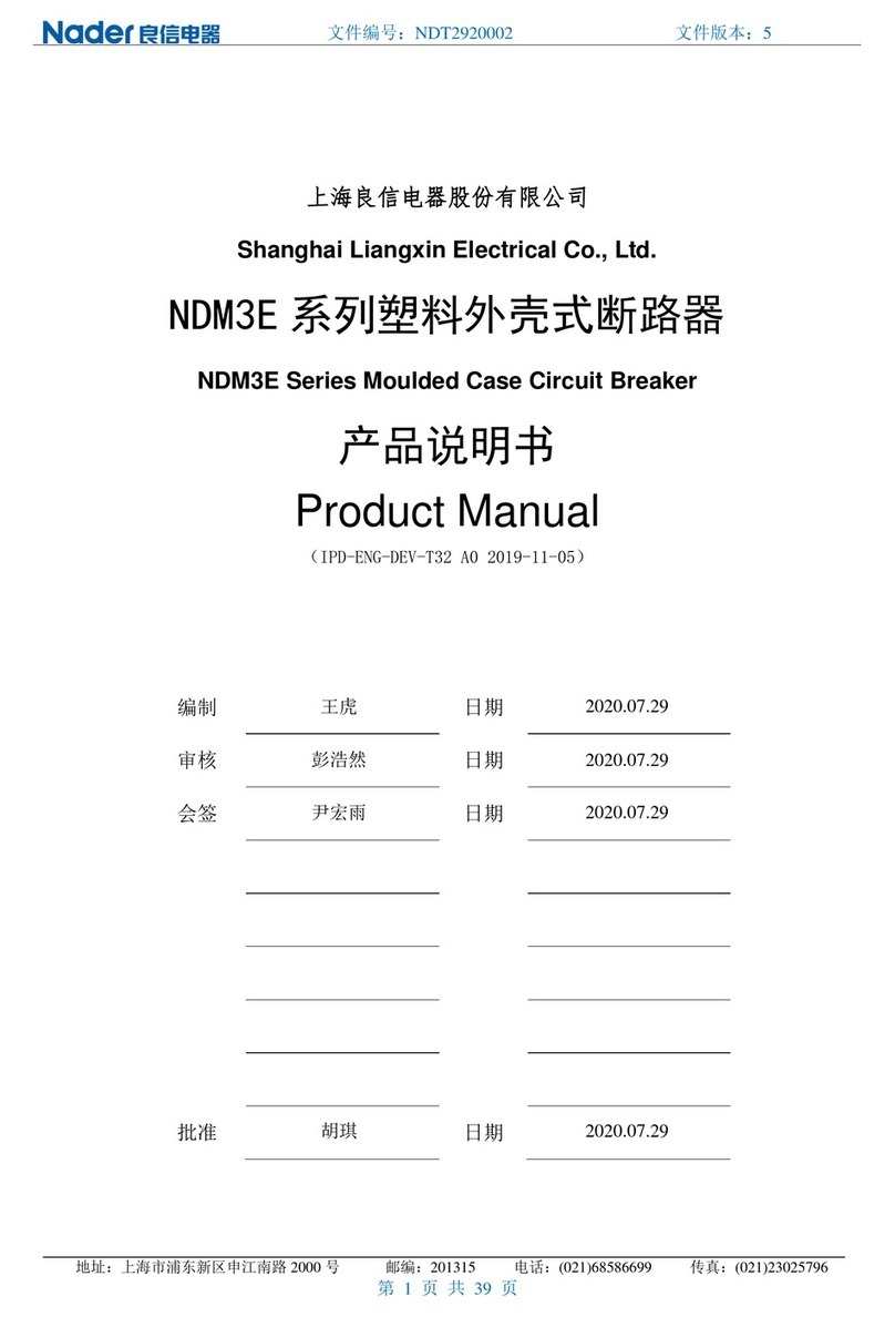
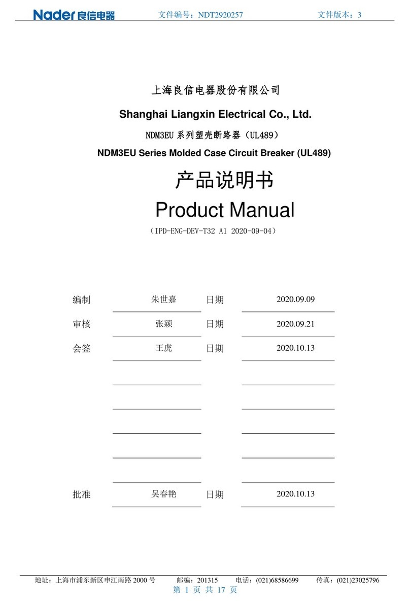
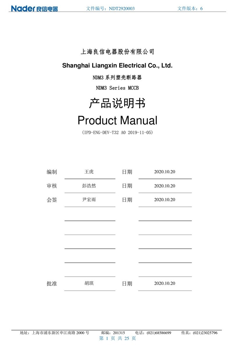
nader NDM3EU-400 User manual

文件名称
Doc. Name
使用说明书
Operating Instructions
文件编号
Doc. Code
NDT2920257
版次
Edition
第1版
Version 1
产品型号
及名称
Product
Model and
Name
NDM3EU-400
塑料外壳式断路器
NDM3EU-400 MCCB
实施日期
Implementation
Date
2019-08-19
上海良信电器股份有限公司
Shanghai Nader Electrical Co., Ltd.
NDM3EU-400 使用说明书
电子式塑壳断路器
NDM3EU-400 Electronic MCCB
Operating Instructions
2019.12.31
文件控制
文件编号
Doc. No.
NDT2920257
版次
Edition
第2版
Version 2
实施日期
Implementation date
2019-08-19
1
目 录 Contents
2 适用范围与用途 Application Scope and Purpose
2 型号说明 Description of Model
3 技术参数 Technical Parameters
7 工作环境 Working Environment
8 外形尺寸和安装尺寸 Dimensions and Installation Dimensions
9 安装 Installation
10 附件说明 Accessories
11 使用和维护 Operation and Maintenance
13 注意事项 Precautions
14 订货须知 Ordering Instructions
2019.12.31
文件控制
文件编号
Doc. No.
NDT2920257
版次
Edition
第2版
Version 2
实施日期
Implementation date
2019-08-19
2
1. 适用范围与用途 Application Scope and Purpose
本断路器主要应用于交流 60Hz,额定工作电压 240V、480V、600V,额定工作电流至 400A 的电
路中作不频繁转换之用。具有过载长延时反时限、短路短延时反时限、短路短延时定时限、短路瞬时,
能保护线路和电源设备不受损坏。
The Circuit-breaker is mainly used in the circuit of AC 60Hz, rated working voltage
240/480V/600V and rated working current up to 400A. Provided with overload long-delay inverse
time, short circuit short-delay inverse time, short circuit short-delay definite time and instantaneous
short circuit ,the breaker can protect the circuit and electric power unit from being damaged.
2. 型号说明 Description of model
型号说明见下表 1:
Description of model is shown as follow Table 1:
表1型号说明
Table 1 Description of model
ND M 3 □- □□/□□□□□□/□
1 2 34 5 6 7 8 9 10 11 12 13
序 号
No.
序号名称
Description
NDM3A
NDM3A
1
企业代号
Enterprise code
ND Nader 牌低压电器
ND Nader brand low-voltage
apparatus
2
产品代号
Product code
M 塑料外壳式断路器
M Molded case circuit breaker
3
设计序号
Design code
3
3
4
派生代号
Derived code
EU:电子式 UL
EU: Electronic type for UL
5
壳架额定电流(A)
Frame rating current
(A)
400
400
6
分断能力代号
Breaking capacity
code
M:高分断型
L:低分断型
M:High interrupting type
L:Low interrupting type
7
极数
3:3 极
3:3P
2019.12.31
文件控制
文件编号
Doc. No.
NDT2920257
版次
Edition
第2版
Version 2
实施日期
Implementation date
2019-08-19
3
Number of poles
8
脱扣器类型
Release type
3:电子脱扣器
3:Electronic type
无
No
9
附件代号
Accessory code
分励脱扣器+双辅助触头:
40
Shunt Trip + Double Auxiliary
Contact:40
无代号:常规接线
No Code: Normal
10
端子形式代号
Terminal type
L:接线柱
L:Lug
无代号:固定式板前接线
No code: Fixed Front Connection
11
接线形式代号
(Wiring type code
Z2H1:插入式板后接线、上
下水平
Z2H2:插入式板后接线、上
下垂直;
Z2H3:插入式板后接线、上
垂直下水平;
Z2H4:插入式板后接线、上
水平下垂直。
Z2H1:Plug-in Rear Connection,
Top and Bottom Horizontal;
Z2H2:Plug-in Rear Connection,
Top and Bottom Vertical;
Z2H3:Plug-in Rear Connection,
Top Vertical and Bottom
Horizontal;
Z2H4:Plug-in Rear Connection,
Top Horizontal and Bottom
Vertical.
12
整定电流 Ir(A)
Setting current Ir(A)
AC 250、AC 300、AC 350、
AC400
AC 250、AC 300、AC 350、AC
400
13
认证代号
(Certification code)
U:UL489
U:UL489 Only
3. 技术参数 Technical parameters
3.1 NDM3EU 主要技术参数见下表 2:
Main technical parameters of NDM3EU are shown as follow Table 2:
表2主要技术参数
Table 2 Main technical parameters
型号、规格 Model and specification
NDM3EU-400
极数 Numbers of poles
3
额定电流(A)
AC 400
整定电流(A)Setting Current (A)
AC 250、AC 300、AC 350、AC 400
额定绝缘电压(V)Rating insulation
voltage (V)
AC800
额定冲击耐受电压(V)
Impulse withstand voltage(V)
8000
额定工作电压(V)
Rating working voltage(V)
AC 240、AC 480、AC 600
AC 240 V: 65/25
分断能力(kA)
Breaking capacity(kA)
AC 480 V: 35/18
2019.12.31
文件控制
文件编号
Doc. No.
NDT2920257
版次
Edition
第2版
Version 2
实施日期
Implementation date
2019-08-19
4
AC 600 V: 22/14
隔离功能 Isolating function
Yes
机械寿命(次)Mechanical endurance(No.
operations)
5000
电寿命(次)Electrical endurance (No.
operations)
1000
海拔 Altitude
<2000m
过载长延时保护 Overload long-delay
protection
(250A,300A,350A,400A)+(12,60,100,150)s
短路短延时保护 Short-circuit short-delay
protection(2,3,4,5,6,7,8,9,10)*Ir
OFF+(0.1,0.2,0.3,0.4)s
电子式保护特性 Electronic protection
characteristics
短路瞬时保护 Short-current instantaneous
protection(3,4,5,6,7,8,9,10,12,14)*In <0.05s
工作温度 Working temperature
-35℃~+70℃(+10℃~+40℃客户 UPS 工
作环境 Used in UPS working environment by
customer)
污染等级 Pollution class
3
防护等级 Protection class
IP20
Circuit breaker:UL489
认证 Certification
Lug:UL486E
附件功能 Accessories
端子罩 Terminal cover
双辅助+分励 (Double Auxiliary Contacts +
Shunt Trip)
插入式(防插拔)+板后接线 (水平、垂直)Plug
in(Pre tripping) + Rear connection(Horizontal,
Vertical)
3.2 NDM3EU 控制器电流、时间调整 Current and time adjustment of NDM3EU controller.
◆控制器电流、时间的调整必须由专业技术人员负责。
Adjustment of current and time of the controller should be carried out by specialized technical
personnel.
3.2.1 NDM3EU 控制器控制面板图及参数组成
Components of the control panel figure and parameter of NDM3EU controller
断路器控制面板组成部分:
Components of the breaker’s control panel:
(1)测试端口 TEST; Test port;
(2)过载长延时整定电流 Ir; Setting current of overload long-delay Ir;
(3)长延时整定时间 Tr; Setting time of long-delay Tr;
(4)短路短延时整定电流 Isd; Setting current of short-circuit short-delay Isd;
2019.12.31
文件控制
文件编号
Doc. No.
NDT2920257
版次
Edition
第2版
Version 2
实施日期
Implementation date
2019-08-19
5
(5)短路短延时整定时间 Tsd; Setting time of short-circuit short-delay Tsd;
(6)短路瞬时整定电流 Ii;Setting current of short-circuit instantaneous Ii;
(7)电源指示灯 Power; Power light;
(8)过载指示灯 Over. Overload light.
控制器控制面板见下图 1:
Control panel of controller is shown as follow Fig. 1:
图1控制器控制面板
Fig. 1 Control panel of controller
3.2.2 NDM3EU 控制器控制面板各部分功能 Functions of each part in control panel of NDM3EU
controller
3.2.2.1 测试端口 Test port
“TEST”端口,NDM3EU 专用测试仪通过该端口与控制器相连,进行测试及调试等操作。
Through this “ TEST” terminal, special tester for NDM3EU is connected to the controller to
conduct testing and debugging etc.
3.2.2.2 整定电流、整定时间调节旋钮 Adjusting knob for setting current 、setting time and tripping
rating 可通过电流、时间的调节,选择适当的组合以达到保护线路、保护设备的作用,此项操作应由专
业技术人员负责。
Suitable combinations of current and time are adjusted by this knob, so as to protect circuits and
devices. This operation should be done by specialized technical personnel.
注:1.Tr 表示当实际电流为 Ir 整定值的 2倍时,断路器动作时间。
如:当 Ir 整定为 400A、Tr 整定为 100s 时,当主回路电流为 2×400A 时,断路器将持续 100s 时后断
开主回路。动作时间精度为±10%。在过载电流下,断路器断开主回路的时间遵循以下公式:
t=(2×Ir/I)2×Tr (其中 I表示过载情况下,主回路实际电流值)
Notes: 1.Tr indicates the operating time of the breaker when actual current is twice of Ir setting.
E.g.: when Ir and Trare set as 400A and 100s respectively, when the current in main circuit reaches
2× 400A, the breaker will disconnect the main circuit after lasting for 100s. The time precision of
action is ±10%. Under the overcurrent, the time that the breaker disconnects the main circuit shall
follow the following format: t=(2×Ir/I)2×Tr(Of which, I stands for the actual current in the main circuit
under overcurrent.)
3.2.2.3 指示灯 Indicator light
(1)过载指示灯 Overload light
过载指示红灯恒亮时,表示实际电流超过了过载长延时整定电流值 Ir 的1.15 倍,处于过载状态,
2019.12.31
文件控制
文件编号
Doc. No.
NDT2920257
版次
Edition
第2版
Version 2
实施日期
Implementation date
2019-08-19
6
并经一定的时间后断路器将断开。
过载指示灯快速闪烁时(频率 4Hz),表示在 3次脱扣动作仍未导致产品脱扣。
Constant light of overload indicator indicates that actual current is more than 1.5 times of
overload long-time delay current setting Ir. The breaker will break the circuit after certain duration.
When the overload indicator flashes fast(frequency is 4Hz),it indicates that the 3 trip has not
caused the product tripped.
(2)电源指示灯 Power light
电源指示灯慢速闪烁时(频率 1Hz),表示正常运行;
电源指示灯快速闪烁时(频率 4Hz),代表控制器自检或系统运行过程中检测到故障。
When the overload indicator flashes slow(frequency is 1Hz),it indicates that the system is
running normally;
When the overload indicator flashes fast (frequency is 4Hz),it indicates that self-checking of
the controller or failure detected during the system operation.
注:两种指示灯应在每半年进行一次常规检验。
Note: Two indicator lights should have once routine inspection per half a year.
3.2.2.4 过载长延时保护 Protection of overload long-delay
a)过载长延时整定电流 Ir,容许偏差±3%;
a) Setting current Ir of overload long-delay, Allowable deviation is ±3%;
b)过载长延时整定时间 Tr,动作时间精度为±10%;
b) Setting time Tr of overload long-delay,Accuracy of action time is±10%;
c)当实际电流 I超过 1.15 倍的过载长延时整定电流值 Ir 时,视为过载状态。过载保护按反时限特
性进行,延时动作时间 tr=(2×Ir/I)2×Tr。
c) When actual current’s value is more than 1.15 times overload long delay setting current Ir,
see as overload status. Overload protection is carried out according to inverse time-delay
characteristics, delay action time tr=(2×Ir/I)2×Tr.
3.2.2.5 短路短延时保护 Short-circuit short-delay protection.
a)短路短延时整定电流 Isd,容许偏差±3%。设置为 off 时,控制器短路短延时保护功能关闭。
a) Setting current Is of short-circuit short-delay, Allowable deviation is ±3%.
b)短路短延时保护动作时间值 Tsd,动作时间精度为理论值±10%(注意:0.1s 和0.2s 这两个档
位,固有绝对误差±40ms)。
b) Action time value of short-circuit short-delay protection, accuracy of action time is ±
10%(Notes: Inherent absolute deviation is ±40ms for 0.1s and 0.2s these two gears).
c)短路短延时保护分为定时限保护和反时限保护两种方案。
c) Short-circuit short-delay protection include two schemes of definite time-delay and inverse
time-delay protection.
当故障电流 1.5×Isd>I≥Isd 时,具有反时限保护特性,即 tsd=(1.5×Isd/I)2×Tsd;
When fault current is 1.5×Isd>I≥Isd, triggered by inversed time-delay characteristics,即 tsd=(1.5×
2019.12.31
文件控制
文件编号
Doc. No.
NDT2920257
版次
Edition
第2版
Version 2
实施日期
Implementation date
2019-08-19
7
Isd/I)2×Tsd;
当故障电流 Ii>I≥1.5×Isd 时,反时限保护转为定时限保护,即 tsd=Tsd。
When fault current is Ii>I≥1.5× Isd , inverse time-delay convert to definite time-delay protection,
tsd=Tsd.
3.2.2.6 短路瞬时保护 Short-circuit instantaneous protection.
a)短路瞬动保护整定电流 Ii,容许偏差±15%;
a) Setting current of short-circuit instantaneous Ii,Allowable deviation is±15%;
b)短路瞬动保护动作时间 Ti<50ms。
b) Action time Ti of Short-circuit instantaneous protection is<50ms.
3.2.2.7 热记忆保护保护 Thermal memory protection
热记忆保护功能维持时间 Tthm=1200s。
Thermal memory protection hold time Tthm is 1200s.
4. 工作环境 Working Environment
4.1 存放的环境条件见下表 3:
Storage condition is shown as follow Table 3:
表3存放环境条件表
Table 3 Storage condition
项目
Item
规范
Specifications
周围温度
Ambient temperature
-40℃~+75℃
相对湿度
Relative humidity
(环境温度 25℃时)≤95%
(when ambient temperature
is 25℃)≤95%
4.2 使用环境 Service environment
(1)不要安装于含有爆炸气体的环境里,否则有引发爆炸的危险;
(1) Do not install the breaker in explosive environment, or hazard of explosion will be resulted;
(2)请勿安装于特别潮湿的地方;
(2) Do not install the breaker in extremely humid locations;
(3)不要安装在外磁场大于地磁场 5倍的地方,否则断路器不能正常工作;
(3) Do not install the breaker in places where external magnetic field is more than 5 times of
the geomagnetic field, or the breaker cannot work normally;
(4)不要安装在振动大于 10m/s2的地方;
(4) Do not install the breaker in places with vibration more than 10m/s2;
(5)不要安装在气体介质能腐蚀金属和破坏绝缘的地方。
(5) Do not install the breaker in places with gaseous medium corrosive to metal and aggressive
2019.12.31
文件控制
文件编号
Doc. No.
NDT2920257
版次
Edition
第2版
Version 2
实施日期
Implementation date
2019-08-19
8
to insulation.
(6)温度降容。
(6) Temperature de-rating.
断路器安装场所的环境要求如下表 4:
Environmental requirements for installation location of breaker are shown as follow Table 4:
表4断路器安装场所的环境要求
Table 4 Environmental requirements for installation location of breaker
项目
Item
规范
Specifications
周围空气温度
Ambient air
temperature
-35℃~+70℃
相对湿度
Relative
humidity
(在+40℃时)不超过 50%,最低温度湿月最不超过+25℃,且该月平均最大相
对湿度不超过 90%,并考虑因温度变化发生在产品表面上的凝露。
The relative humidity of the air does not exceed 50% (at +40℃), the lowest
temperature in the most humid month should not exceed +25℃, and the
highest humidity in this month should not exceed 90% while condensation
on breaker surface caused by temperature change should be taken into
consideration.
海拔高度
Altitude
不超过 2000m
Lower than 2000m
污染等级
Pollution
degree
3级
Level 3
温度降容系数见下表 5:
Temperature de-rating coefficient is shown as follow Table 5:
表5温度降容系数
Table 5 Temperature de-rating coefficient
温度
Temperature
+40℃
+45℃
+50℃
+55℃
+60℃
+65℃
+70℃
降容系数
De-rating
Coefficient
1
1
1
0.978
0.957
0.934
0.911
注:当使用环境温度低于 40℃时,产品可正常使用,不存在降容。
Notes:When ambient temperature is less than 40℃, breaker can be used normally without any
de-rating.
2019.12.31
文件控制
文件编号
Doc. No.
NDT2920257
版次
Edition
第2版
Version 2
实施日期
Implementation date
2019-08-19
9
5、外形尺寸和安装尺寸 Overall and installation dimensions
外形尺寸见下图 2:
Overall dimensions are shown as follow Fig. 2:
图2外形尺寸
Fig. 2 Overall dimensions
安装尺寸见下表 6:
Installation dimensions are shown as follow Table 6:
表6安装尺寸
Table 6 Installation dimensions
安装尺寸 Installation dimension
型号 Model
长L
(mm)
宽W
(mm)
高H
(mm)
Y
(mm)
X(mm)
孔径Φ
(mm)
断路器 Circuit
breaker
277
150
123
204
48
6
断路器+插拔
Circuit breaker
+ Plug in
357
150
155
158
70
6.2
6、安装 Installation
6.1 绝缘测试 Insulation test
本断路器出厂前已按标准规定绝缘测试。因断路器带有电子线路板,安装前如进行复测,必须按如
下步骤:
The breaker has gone through specified standard insulation test before factory delivery. Because
many PCBs are installed in the breaker, for re-testing, please conduct tests according to following
2019.12.31
文件控制
文件编号
Doc. No.
NDT2920257
版次
Edition
第2版
Version 2
实施日期
Implementation date
2019-08-19
10
procedures:
(1)用 500 Vdc 兆欧表;
(1) Use a 500 Vdc megameter;
(2)在断路器处于断开状态,对进出连接板 1-2、3-4、5-6 之间,和 1、3、5连接板(3个连接板
用导线相连)与外壳之间(外壳用金属箔覆盖)分别进行;
(2) Place the breaker in open status, carry out test between 1-2, 3-4 and 5-6 connection boards,
as well as between the 1, 3 and 5 connection boards (connected with wires) and the breaker shell
(covered by metal foil);
(3)对接至主电路的分励脱扣器,在进线与断路器外壳间;
(3) Test should be done in position between incoming wire and breaker shell to test shunt release
in the main circuit;
(4)绝缘电阻不小于 12MΩ。
(4) Insulation resistance should not be lower than 12MΩ.
6.2 安装方式 Mounting method
请安装在如金属等阻燃物上。断路器可垂直安装见下图 3,也可以水平安装见下图 4。Please
install the breaker on flame retardants such as metal, etc. It can be installed vertically is shown as
follow Fig. 3 or horizontally is shown as follow Fig. 4.
产品垂直安装时,安装面与垂直面的倾斜角度≤±22.5°。When the product is installed vertically,
the angle of inclination between the installation surface and vertical surface shall be ≤±22.5°.
图3直安装 图4水平安装
Fig. 3 Vertical installation Fig. 4 Horizontal installation
7附件说明 Accessory
7.1 分励脱扣器 Shunt release
根据引出的导线编号接入电源,当分励脱扣器的外加电压介于额定控制电源电压的 55%-110%之间
时,能可靠分断断路器。
Power supply is connected to the shunt release according to output wire number, At rated
2019.12.31
文件控制
文件编号
Doc. No.
NDT2920257
版次
Edition
第2版
Version 2
实施日期
Implementation date
2019-08-19
11
control supply voltage of 55%-110%, shunt release should be reliable to trip breakers.
分励脱扣器功耗见下表 7:
Power dissipation of Shunt release is shown as follow Table 7:
表7分励脱扣器功耗
Table 7 Power dissipation of Shunt release
额定工作电压
Rating working voltage
功耗
Power dissipation
AC 120 V
210 W
分励脱扣器接线图见下图 5:
Wiring diagram of shunt release is shown as follow Fig. 5:
图5分励脱扣器接线图
Fig. 5 Wiring diagram of shunt release
7.2 辅助触头 Auxiliary contact
7.3 辅助触头接入相应外围控制电路 Peripheral control circuits of connection of auxiliary contacts
辅助触头技术参数见下表 8:
Technical Data of auxiliary contact is shown as follow Table 8:
表8辅助触头技术参数
Table 8 Technical Data of auxiliary contact
额定工作电压
Rated Operational Voltage
额定工作电流
Rated Operational Current
AC 120 V
AC 5 A
AC 240 V
AC 3 A
AC 24 V
AC 300 mA
AC 48 V
AC 10 mA
辅助触头状态指示表见下表 9:
Status indication of auxiliary contact is shown as follow Table 9:
表9辅助触头状态指示表
Table 9 status indication of auxiliary contact
附件名称
断路器状态
线路接通状态
2019.12.31
文件控制
文件编号
Doc. No.
NDT2920257
版次
Edition
第2版
Version 2
实施日期
Implementation date
2019-08-19
12
Accessory
name
Status of the breaker
Connection status of the circuit
“分”或“自由脱扣”
“Open” or “Free tripped”
辅助触头
Auxiliary
contact
“合”
“Close”
“接通”与“断开”相互转换
Mutual transferring between “On” and “Off”
8使用和维护 Application & Maintenance
8.1 运行前检查和准备 Checks and preparation before operation
运行前应检查以下各项 Check following items before operation:
(1)核对接线是否正确;
特别是检查断路器的输入端子(1、3、5)应接入电源线,输出端子(2、4、6)应接至负载线;
(1)Check for correct wiring;
Check that the input terminals (1, 3 and 5) of the breaker are connected with power wires,
while output terminals (2, 4 and 6) are connected with load wires.;
(2)确认端子间或暴露的带电部分没有短路或对地短路情况;
(2) Check that no short circuit or short to ground occurs between terminals of opposite polarity
or exposes live parts;
(3)确认端子连接和固定螺钉均应紧固无松动。
(3) Check that terminal connection and fixing bolts are fastened without looseness.
8.2 试运行 Commissioning
按9.1 条各项全部确认无异常情况后,可以进行试运行。
After confirming that all items in Section 9.1 are normal, then start the commissioning.
(1)用户根据需要在调节面板上调整好 Ir,Tr,Isd,Tsd,Ii 等;
(1) Adjust values of Ir,Tr,Isd ,Tsd,Ii etc. in panel as needed;
(2)扳动操作手柄,投入电源;
(2) Operate the handle and connect power supply;
(3)断路器主电路带电后,按紧急脱扣按钮,断路器应脱扣,操作手柄处于脱扣位置;
(3) After the main circuit of the breaker is electrified, press the emergency trip button with the
handle in tripped position to trip the breaker;
(4)如果试运行都能满足,可投入运行。
(4) If commissioning is satisfactory, the breaker can be put in operation.
8.3 维护 Maintenance
维护检查必须有专业技术人员负责。
Maintenance checks should be done by specialized technical personnel.
用户如需选用内、外附件,按所订型号由本公司提供,以保证质量。如用户自行选购或改装,本公
2019.12.31
文件控制
文件编号
Doc. No.
NDT2920257
版次
Edition
第2版
Version 2
实施日期
Implementation date
2019-08-19
13
司不能负责。
User should use internal and external accessories provided by Nader so as to endure their
quality; Nader should not be held reliable for purchase of accessories from other companies or
authorized modifications.
在执行维护操作前,必须先完成下列操作:
Follow following steps before conducting maintenance:
(1)使断路器分闸;
(1) Open the breaker;
(2)断开电源与断路器的连接(包括主电路、辅助电路);
(2) Disconnect power supply and breaker (including main circuit and auxiliary circuits);
(3)将断路器从安装位置上卸下(一般用于插入式,固定式推荐也如此)。
(3) Remove the breaker from its installation position (normally for plug-in installation; it is
recommended to do so for a fixing one).
断路器维护在正常操作条件下每年一次,在非正常条件下每半年一次,以下为维护内容:
Maintenance of breaker is carried out yearly under normal use and every six months under
abnormal use. The maintenance includes following procedures:
(1)再扣断路器,合、分断路器,在断路器合闸时用脱扣按钮使断路器脱扣,往复操作 5次,断
路器应能可靠进行再扣、合、分、脱扣动作;
(1) Re-trip the breaker, close and open the breaker, use trip button to trip the breaker when it
is closed; repeat for 5 times to check that the breaker can reliably re-trip, open, close and trip;
(2)清除断路器表面及连接处的灰尘(用清洁、干燥的抹布擦拭);
(2) Clean dust on breaker surface and connections (wipe with clean and dry cloth);
(3)清洁隔弧板,如必要则需要更换隔弧板;
(3) Clean the flash barrier; replace it if necessary;
(4)绝缘测试(见 6.1);
(4) Carry out insulation test (see Section 6.1);
(5)检查所有连接情况,用砂布擦除氧化物,用可溶解剂清洁,拧紧螺栓和螺母;
(5) Check condition of all connections. Wipe away oxidations with abrasive cloth and clean with
soluble agent. Screw bolts and nuts tight;
(6)控制器整定值与报警故障灯显示功能测试:应使用我公司的 NDM3EU 专用测试仪器与断路
器的 TEST 端口连接,检验各个设定参数,以保证参数设定与旋钮指示一致;
(6) Test of controller setting values: use a tester specialized for NDM3EU provided by Nader to
connect with TEST terminal of the breaker. Check setting of each parameter to ensure that
parameter setting is consistent with knob indication;
(7)如果断路器还装有其它内、外部附件,应逐一检查各个附件,以确保其处于正常工作状态。
(按照 7 附件说明 详细内容进行测试)
(7) If other internal or external accessories are installed in the breaker, check them one by
2019.12.31
文件控制
文件编号
Doc. No.
NDT2920257
版次
Edition
第2版
Version 2
实施日期
Implementation date
2019-08-19
14
one to ensure they are in normal working condition (carry out test according to Section 7: Detailed
accessory descriptions).
9注意事项 Notes
9.1 安装注意事项 Precautions in installation
(1)断路器本体、底板(板后接线用)、底座(插入式接线用)固定在安装板上;
(1) Breaker body, bottom plate (for wiring behind the plate) and base (for plug-in wiring) are
mounted on the installation board;
(2)与主电路连接必须由具有专业资格的人员进行配线作业;
(2) For connection with the main circuit, the wiring should be done by professional qualified
personnel;
(3)确认输入电源处在完全断开的情况下,才能进行配线作业;
(3) Wiring should be done after confirmation of complete disconnection of input power supply;
(4)必须安装本体后再进行配线。
(4) Wiring should be done after installation of breaker body.
9.2 运行注意事项 Precautions in operation
(1)湿手不能操作断路器,否则可能发生电击事故;
(1) Do not operate the breaker with wet hands, or electric shock would be resulted;
(2)断路器不能频繁操作,否则会缩短断路器的使用寿命;
(2) Frequent operation will shorten service life of the breaker;
本产品是在完善的品质管理体系下制造的,当万一发生故障时,对保修期与售后服务特作如下说明:
This product is manufactured in a sophisticated quality management system. In case of fault,
following warranty and after services clauses are applicable:
保修期/ Warranty period
在用户遵守保管和使用条件下,从本公司发货之日起,不超过 36 个月,断路器封印完好,产品如
因制造质量问题而发生损坏或不能正常使用时,本公司负责无偿修理或更换。但是,如由于下述原因引
起的故障,即使在保修期内亦作有偿修理或更换。
On the premise of user’s compliance with reservation and use specifications of the breaker, for
breakers whose delivery date is within 36 months from now and whose seals are intact, Nader will
repair or replace any of these breakers which are damaged or cannot work normally due to
manufacture quality. However, as for faults caused by following reasons, Nader would repair or
replace the breaker with a charge even it is still in warranty.
(1)由于使用错误、自行改装及不适当的维修等原因;
(1) Misuse, unauthorized modifications and improper repair, etc.;
(2)超过标准规范的要求使用;
(2) Use during which standards and specifications are violated;
(3)购买后由于摔落及安装过程中发生损坏等原因;
2019.12.31
文件控制
文件编号
Doc. No.
NDT2920257
版次
Edition
第2版
Version 2
实施日期
Implementation date
2019-08-19
15
(3) Damages caused by falling or improper installation, etc.;
(4)地震、火灾、雷击、异常电压、其他天灾及二次灾害等原因。
(4) Natural disasters and secondary disasters such as earthquake, fire, thunder and abnormal
voltage, etc..
售后服务/ After-sales service
(1)出现故障时,请与供货商或本公司售后服务部门联系;
(1) Contact distributor or Nader after-sales department in case of breaker fault;
(2)保修期内的修理或更换:由于本公司制造上的问题所造成的故障,作无偿修理,以至更换;
(2) Breakers in warranty will be repaired or replaces; for faults caused by manufacture of
Nader, product will be repaired for free or even replace with a new one;
(3)超过保修期后的修理或更换:在修理后能维持功能的场合下,作有偿修理,否则可作有偿更
换。
(3) Repair or replacement of breaker with expired warranty: paid repair will be done after
which breaker can functions normally, or the breaker will be replaced with a charge.
10 订货须知 Ordering Instruction
10.1 用户务必确认对本产品技术资料已有详细了解,并应根据断路器将来使用的场合,按“订货规范”表
订货;
10.1 Customer should confirm that he or she is familiar with technical files of this product, and place
order by the “Ordering Specifications” form according to future application of circuit breaker;
10.2 如用户订货时对智能控制器保护参数不作要求,本公司将按规格型号默认配置。
10.2 If customer has not put forward any requirement on protection parameters of the intelligent
controller upon ordering, Nader will deliver the product in default configurations of the model and
specification.
总机电话:Telephone of switchboard: 021-68586699
营销传真 Marketing fax: 021-23075796
技术热线 Technical hotline: 400-99-02706
邮政编码 Zip Code: 201315
股票代码 Stock Code: 002706
电子邮箱 Email: [email protected]
公司网址 Website: www.sh-liangxin.com
总部地址:上海市浦东新区申江南路 2000 号
Address of headquarter: No.2000, Shenjiang South Rd., Pudong
New District, Shanghai
2019.12.31
文件控制

Other nader Circuit Breaker manuals

nader NDM3L Series User manual

nader

nader NDM3L Series User manual

nader NDM3Z Series User manual

nader

nader NDM3Z Series User manual

nader NDM3EU-225 User manual

nader

nader NDM3EU-225 User manual

nader NDM3 Series User manual

nader

nader NDM3 Series User manual

nader NDM2L Series User manual

nader

nader NDM2L Series User manual

nader NDM3E Series User manual

nader

nader NDM3E Series User manual

nader NDM3E Series User manual

nader

nader NDM3E Series User manual

nader NDZ3X-100B/Z User manual

nader

nader NDZ3X-100B/Z User manual

nader NDM2E Series User manual

nader

nader NDM2E Series User manual

nader NDM3EU Series User manual

nader

nader NDM3EU Series User manual

nader NDM5-160 Series User manual

nader

nader NDM5-160 Series User manual

nader NDM2E Series User manual

nader

nader NDM2E Series User manual

nader NDM2 Series User manual

nader

nader NDM2 Series User manual

Popular Circuit Breaker manuals by other brands

Eaton Power Defense PDG2 Instruction leaflet

Eaton

Eaton Power Defense PDG2 Instruction leaflet

Siemens PSR Instructions, Installation, Operation, Maintenance

Siemens

Siemens PSR Instructions, Installation, Operation, Maintenance

Westinghouse DB-50 instructions

Westinghouse

Westinghouse DB-50 instructions

ABB Emax manual

ABB

ABB Emax manual

HSS Hire RCD 40970 Operating & safety guide

HSS Hire

HSS Hire RCD 40970 Operating & safety guide

Eaton Cutler-Hammer Digitrip 1150 instructions

Eaton

Eaton Cutler-Hammer Digitrip 1150 instructions

Fonrich FR-DCBS-AFS8B user manual

Fonrich

Fonrich FR-DCBS-AFS8B user manual

Eaton NHI-E PKZ0 Series installation instructions

Eaton

Eaton NHI-E PKZ0 Series installation instructions

Siemens 3VT9200-8CB30 operating instructions

Siemens

Siemens 3VT9200-8CB30 operating instructions

LEGRAND Enedis DPX 3 250AB manual

LEGRAND

LEGRAND Enedis DPX 3 250AB manual

Eaton PKE-SWD-CP Instruction leaflet

Eaton

Eaton PKE-SWD-CP Instruction leaflet

Leviton 16693 Installation

Leviton

Leviton 16693 Installation

GE EntelliGuard AKR30S-800A installation manual

GE

GE EntelliGuard AKR30S-800A installation manual

Eaton NZM2-XKR Instruction leaflet

Eaton

Eaton NZM2-XKR Instruction leaflet

Siemens VT63 operating instructions

Siemens

Siemens VT63 operating instructions

Siemens Sentron 8UD1721-0AB Series operating instructions

Siemens

Siemens Sentron 8UD1721-0AB Series operating instructions

Eaton Ulusoy URING12-24-LLC-SF6 user manual

Eaton

Eaton Ulusoy URING12-24-LLC-SF6 user manual

WAGO EPSITRON 787-1668 Series manual

WAGO

WAGO EPSITRON 787-1668 Series manual

manuals.online logo
manuals.online logoBrands
  • About & Mission
  • Contact us
  • Privacy Policy
  • Terms and Conditions

Copyright 2025 Manuals.Online. All Rights Reserved.