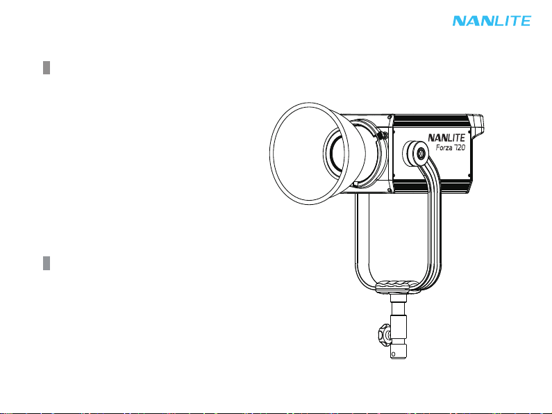
NANLITE Forza 720 User manual
Other NANLITE Spotlight manuals

NANLITE
NANLITE FS-300B User manual

NANLITE
NANLITE Forza 720 User manual

NANLITE
NANLITE Forza 300B User manual

NANLITE
NANLITE FS-150 User manual

NANLITE
NANLITE P-100 User manual

NANLITE
NANLITE Forza 150 User manual

NANLITE
NANLITE Forza 60 User manual

NANLITE
NANLITE FS-150B User manual

NANLITE
NANLITE FS-60B User manual

NANLITE
NANLITE Forza 60B User manual

Popular Spotlight manuals by other brands

Foscam
Foscam S41/SPC user manual

EuroLite
EuroLite LED SLS-144 UV Floor Spot user manual

Guangzhou Yinhe Lighting&Sound Equipment Factory
Guangzhou Yinhe Lighting&Sound Equipment Factory NE-204 user manual

LIVARNO home
LIVARNO home 375304 2101 Installation, operating and safety information

Leviton
Leviton Ellipsoid 5/50 user guide

Vector
Vector SL3AKV instruction manual

Quantum
Quantum Q262 Product data sheet

EUROSPOT
EUROSPOT C51 instruction manual

DTS
DTS MINI BRICK ARC user manual

Federal Signal Corporation
Federal Signal Corporation VISIBEAM II Installation, operation and maintenance instructions

ACME
ACME LED-MS350B user manual

EuroLite
EuroLite Akku flat light 1 user manual