manuals.online logo
Brands
  1. Home
  2. •
  3. Brands
  4. •
  5. NAPCO
  6. •
  7. Keypad
  8. •
  9. NAPCO RP1054e User manual

NAPCO RP1054e User manual

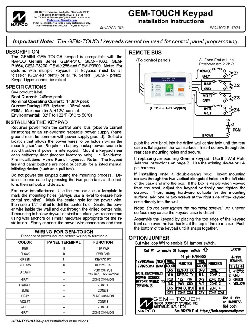
DESCRIPTION
The RP1054e is a user-friendly backlit keypad designed
for use with Napco MA1000e, MA1008e and MA1010 con-
trol panels, and for replacement purposes in MA854,
MA1008-series and MA1010-series panels. A large 7-seg-
ment alphanumeric display functions as a readout for con-
trol-panelinformationandzoneidentification.Installationis
quick and easy on only four wires.
This manual provides installation information only. Refer
to the accompanying User’s Guide (OI160) for keypad
functions and operation, and to the installation manual
furnishedwith thecontrol panelfor panelmounting, wiring,
and programming information.
SPECIFICATIONS
Operating Voltage: 9.0--13.0Vdc (supplied by control
panel)
Current: 40mA* typical
Wiring Length: 1 keypad, 1000’ max.; 5 keypads, 300’
max. using #22AWG wire)
Dimensions: 43⁄8’’ x 57⁄8’’ x 11⁄16’’ (HxWxD)
*Subtract from available combined standby current of
control panel.
MOUNTING
Opening the Keypad. There are two slots along the
bottom edge of the keypad about 1 inch from each side.
To open, insert a medium screwdriver into either slot and
push up with a slight twisting motion to release the retainer
tab. Repeat for the other slot. Pull out at the bottom and lift
off the two hooks at the top.
This keypad features a handy pull-up reference label.
(Thislabel mustbe usedinUL installations.)Before mount-
ing the keypad onto the wall, push the Sliding Label Plate
(with label and felt backing affixed and handle facing for-
ward) down the guides at the rear of the keypad until it
snaps into place. Once installed, the Sliding Label Plate
cannot be removed without first removing the keypad from
the wall.
Wheninstalling the rearcase, besurethat thewords ‘‘UP’’
and‘‘TOP’’(moldedintothecase)areproperlyoriented.The
rear case is provided with a variety of holes to accommo-
datevirtually anymounting situation.The fourangled elon-
gated holes are for mounting directly into a wall using
appropriate screws; these holes will allow levelling adjust-
ment. The four corner holes may be used when replacing
an RP854 Keypad with RPB-1 Backplate for surface
mounting directly onto a wall. The RP1054e replaces both
the keypad and the backplate. If installing into a double-
gang box, insert mounting screws through the two vertical
elongated holes on the left side of the case and into the
box. If the box is visible when viewed from the front, adjust
the keypad vertically, then tighten the screws. Then, using
hardwaresuitableforthemountingsurface,addoneortwo
screws at the right side of the keypad case directly into the
wall to ensure a secure installation.
WIRING
Wire the keypad to the control panel terminals shown in
Table 1. Note: If using a soldering iron, be careful not to
splash solder onto the keypad circuit board or compo-
nents, as damage could result.
Keypad Wire
Color
MA854 MA1000e/M
A1008e
MA1008 MA1010
Yellow 1 9 5 6
Green 2 10 6 7
Red 3 7 3 3
Black 4 8 4 4
White to normally-open momentary-contact remote
panic switch(es)
White
Table 1. Keypad wiring to control-panel terminals.
Remote Panic. To connectaremote panicbutton,splice
thetwowhitewires toanormally-openmomentary-contact
pushbutton switch. Similarly, additional panic buttons may
bewired inparallelwith thefirst, asneeded.If remotepanic
willnotbeused,insulatebothwhiteleads,asashortacross
them will cause a panic alarm. Note that in UL installations,
remotepanic buttonsmust belocatedin thesame roomas
the keypad.
Keypad Panics. The RP1054e Keypad supports F/P/A
(Fire/Police/Auxiliary) panics. To enable Fire and Auxiliary
Panics, cut Jumper E (see JUMPER OPTIONS). If enabled,
each is tripped by simultaneously pressing the following
pairs of panic buttons:
•Fire Panic: press Keys [9/F] and [#].
•Police Panic: press Keys [*/P] and [#].
•Auxiliary Panic: press Keys [B/A] and [#].
Note: If used as a replacement keypad in MA854 or
MA1008 systems, which do not have the F/A/P-panic fea-
ture, or in MA1010 systems without F/P/A panic, Jumper E
RP1054e KEYPAD
© NAPCO 1991 DESIGN PATS. PENDING WI578A 3/92
NAPCO SECURITY SYSTEMS, INC.
333 BAYVIEW AVENUE
AMITYVILLE, NEW YORK 11701
SALES REPAIRS & TECHNICAL SERVICE
TOLL FREE: (800) 645-9445
TECHNICAL SERVICE DIRECT LINE
TOLL FREE: (800) 645-9440
INSTALLATION INSTRUCTIONS
must remain intact.
Backlighting. Backlighting requires no additional wiring.
In normal use, the keypad is always dimly backlit. To
disable backlighting, see JUMPER OPTIONS.
JUMPER OPTIONS
Several jumpers provide a variety of options. Viewing the
keypad from the front, they are conveniently located at the
top edge (Jumper D) and along the right side (top to
bottom:Jumpers C, B,A andE) foreasy access.To further
identifythe locationofthe jumpers,referto thelabelaffixed
to the fishpaper on the back of the board.
Disable Keypad Panic. CutJumper Ato disableall three
keypad-panic features and the two white remote-panic
wires.
Disable Keypad Sounder. Cut Jumper B to completely
disable the sounder. Do not disable the sounder in UL
installations.
Disable Touchpad Backlight. Cut Jumper C to disable
touchpadbacklighting.(Thiswillconserveof15mA keypad
current.)
Reduce Touchpad Backlight. Cut Jumper D to reduce
backlight intensity. (This will conserve 6mA of keypad cur-
rent.)
Activate Fire & Aux. Panics. Cut Jumper E to enable
F/P/A keypad panics.
COMPLETING THE INSTALLATION
To reassemble the keypad after installation, hang the top
of the front panel onto the hooks in the rear case and push
infirmlyatthebottomuntiltheretainertabssnapintoplace.
(If difficulty is encountered, push the retainer tabs up
slightly using a screwdriver, as when removing.)
HOLD-DOWN FUNCTIONS
The keypad functions listed in Table 2 are selected by
holding down the indicated key for about 2 seconds (until
a beep sounds).
Key Function
[1] Bell/Battery Test
[2] Display Bypass*
[3] Display Status*
[4] Instant Protection
[5] Chime
[6] Telco Test; Manual Download**
[7] Fault Find
[8] Program
[9] Reset
[B] Alarm History*
*Keep button depressed until all zones have been dis-
played.
**Secondary hold-down function accessible only within
5 seconds after arming and disarming.
Table 2. Hold-Down Functions
To review the available functions at the keypad, pull up
the Sliding Label Plate at the top of the keypad to expose
the ‘‘ready-reference’’ list of both hold-down functions and
zone descriptions.
System Trouble Indications (MA1000e-Series only)
(Not in MA854 or earlier MA1000-Series panels). The
following system troubles will display at the keypad,
whether armed or disarmed, accompanied by flashing
LEDs. The indication may be temporarily reset by holding
down Reset Key [9] in order to check zone status and/or
armthesystem. Ifthesystemtroubleisnotcorrected, itwill
return after about 3 minutes.
1: Ac Failure. Displays when ac power is restored after
a lengthy power failure (and the backup battery is dead).
2. Low Battery. Displays when battery terminal voltage
drops below its specified level.
3. Failure to Communicate. Indicates a transmission
failure. Hold down Key [9] to reset the keypad, then hold
downKey[6]totestthephonelines.Ifthetestissuccessful,
the display will clear; otherwise it will return, indicating a
need for service.
7. Auto-Download Failure. (Where available.) Indicates
failure of a Function-6 Auto-Download from the PCD2000.
Reset the display by holding down Key [9], then try again
to download the program.
KEYPAD PROGRAMMING (MA1000-Series only)
The following keypad functions are enabled only in the
DealerProgramMode.Forprogramminginstructions,refer
to the installation manual furnished with the control panel.
Key [1] - PRIOR. Sequences backward to the previous
location.
Key [2] - NEXT. Advances to the next location.
Key [3] - NEXT. Same as Key [2].
Key [4] - DATA UP. Selects the data for the chosen
location: numbers 1--9, 0 and letters B, C, D, E, and F, in
ascending order.
Key [5] - CLEAR. Clears the data from the selected loca-
tion.
Key [6] - PRIOR. Same as Key [1].
Key [7] - DATA DOWN. Selects the data for the chosen
location: numbers 1--9, 0, and letters B, C, D, E, and F, in
descending order.
Key [8] - EXIT. All LEDs will light. Enter Dealer Program
Code with 10 seconds to verify and exit.
Key [B] - SET LOCATION.Entera3-digitlocationnumber.

Other manuals for RP1054e

4

Other NAPCO Keypad manuals

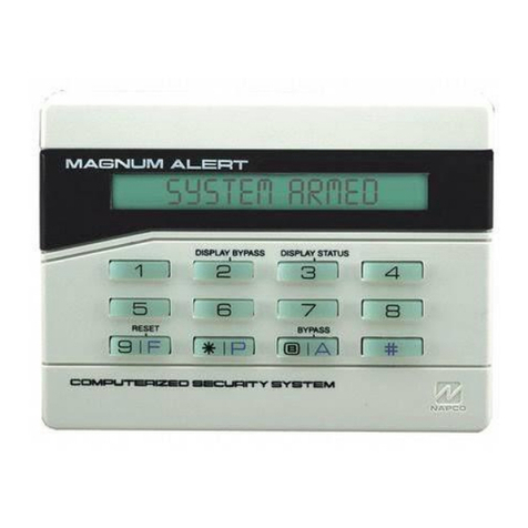
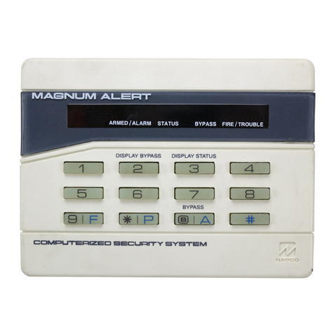
NAPCO MAGNUM ALERT RP3000 KEYPAD User manual

NAPCO

NAPCO MAGNUM ALERT RP3000 KEYPAD User manual

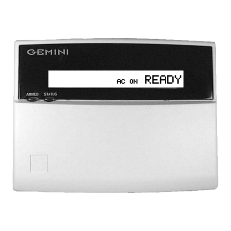
NAPCO Gemini GEM-RP2ASe2 User manual

NAPCO

NAPCO Gemini GEM-RP2ASe2 User manual

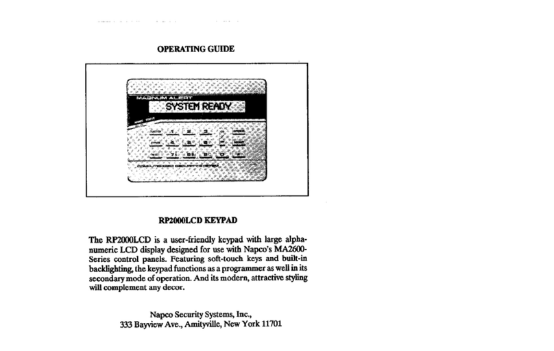
NAPCO Magnum Alert RP2000LCD User manual

NAPCO

NAPCO Magnum Alert RP2000LCD User manual

NAPCO RP1016LCD User manual

NAPCO

NAPCO RP1016LCD User manual

NAPCO Magnum Alert RP1000ELCD User manual

NAPCO

NAPCO Magnum Alert RP1000ELCD User manual

NAPCO MAGNUM ALERT RP1016E KEYPAD User manual

NAPCO

NAPCO MAGNUM ALERT RP1016E KEYPAD User manual

NAPCO RP1054e User manual

NAPCO

NAPCO RP1054e User manual

NAPCO MAGNUM ALERT RP1016E KEYPAD User manual

NAPCO

NAPCO MAGNUM ALERT RP1016E KEYPAD User manual

NAPCO GEM-RP2AS User manual

NAPCO

NAPCO GEM-RP2AS User manual

NAPCO Gemini GEM-P1632 User manual

NAPCO

NAPCO Gemini GEM-P1632 User manual

NAPCO Gemini GEM-RP4C User manual

NAPCO

NAPCO Gemini GEM-RP4C User manual

NAPCO GEM-K800 User manual

NAPCO

NAPCO GEM-K800 User manual

NAPCO RP1016LCD User manual

NAPCO

NAPCO RP1016LCD User manual

NAPCO RP1054e User manual

NAPCO

NAPCO RP1054e User manual

NAPCO RPXP6GT User manual

NAPCO

NAPCO RPXP6GT User manual

NAPCO RP2000LED User manual

NAPCO

NAPCO RP2000LED User manual

NAPCO Gemini GEM-RP2ASe2 User manual

NAPCO

NAPCO Gemini GEM-RP2ASe2 User manual

NAPCO Gemini GEM-RP1CAe2 User manual

NAPCO

NAPCO Gemini GEM-RP1CAe2 User manual

NAPCO Gemini GEM-DXRP1 User manual

NAPCO

NAPCO Gemini GEM-DXRP1 User manual

NAPCO Gemini GEM-RP1CAe2 User manual

NAPCO

NAPCO Gemini GEM-RP1CAe2 User manual

NAPCO Magnum Alert User manual

NAPCO

NAPCO Magnum Alert User manual

NAPCO MAGNUM ALERT RP1000E LCD KEYPAD User manual

NAPCO

NAPCO MAGNUM ALERT RP1000E LCD KEYPAD User manual

NAPCO GEMINI GEMC-255 User manual

NAPCO

NAPCO GEMINI GEMC-255 User manual

NAPCO Gemini GEM-K4RF User manual

NAPCO

NAPCO Gemini GEM-K4RF User manual

Popular Keypad manuals by other brands

Channel Vision A0127W user guide

Channel Vision

Channel Vision A0127W user guide

Storm AXS Code Master installation instructions

Storm

Storm AXS Code Master installation instructions

CDVI CAASE Installation

CDVI

CDVI CAASE Installation

Satel CR-MF5 manual

Satel

Satel CR-MF5 manual

Leviton GreenMAX DRKDN-C1W installation manual

Leviton

Leviton GreenMAX DRKDN-C1W installation manual

Protection One 6150RFPL2 Installation and setup guide

Protection One

Protection One 6150RFPL2 Installation and setup guide

CADDX Ranger 9050 user manual

CADDX

CADDX Ranger 9050 user manual

Assa Abloy DK-16 manual

Assa Abloy

Assa Abloy DK-16 manual

Savant WPB 106 Series Quick reference guide

Savant

Savant WPB 106 Series Quick reference guide

Panasonic KX-HNK101 operating instructions

Panasonic

Panasonic KX-HNK101 operating instructions

Jaycar LA5214 user manual

Jaycar

Jaycar LA5214 user manual

Vimco LUTRON Sivoya QED seeTouch SVQ-2WD manual

Vimco

Vimco LUTRON Sivoya QED seeTouch SVQ-2WD manual

Defiant G7X2D01AA Instructions & assembly

Defiant

Defiant G7X2D01AA Instructions & assembly

ring Alarm Keypad 2nd Generation user manual

ring

ring Alarm Keypad 2nd Generation user manual

Honeywell Ademco 6150V user guide

Honeywell

Honeywell Ademco 6150V user guide

YASKAWA JVOP-KPLCA04A Series installation manual

YASKAWA

YASKAWA JVOP-KPLCA04A Series installation manual

CADDX NX-148 installation manual

CADDX

CADDX NX-148 installation manual

Access Security Products KP401-IE user manual

Access Security Products

Access Security Products KP401-IE user manual

manuals.online logo
manuals.online logoBrands
  • About & Mission
  • Contact us
  • Privacy Policy
  • Terms and Conditions

Copyright 2025 Manuals.Online. All Rights Reserved.