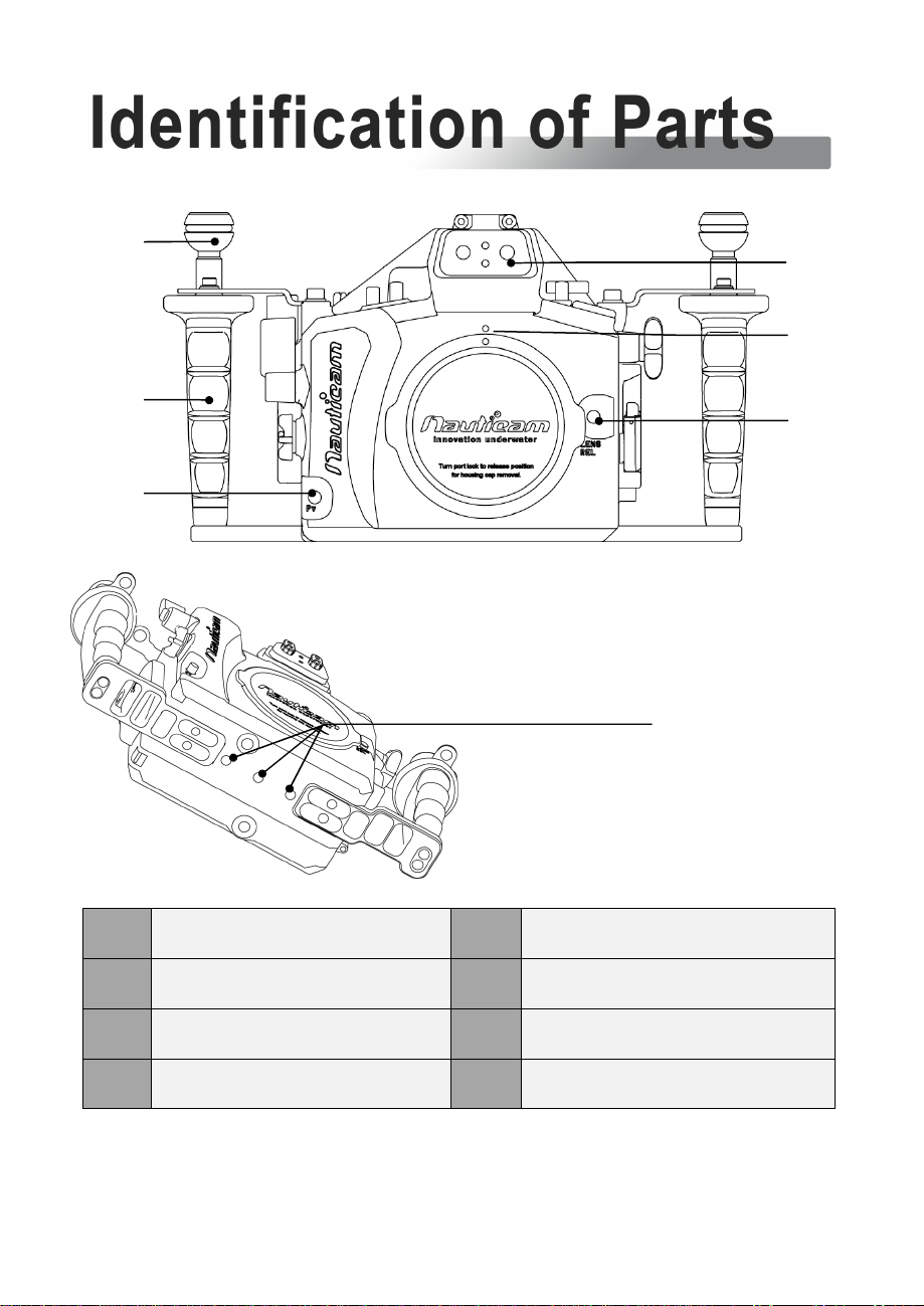
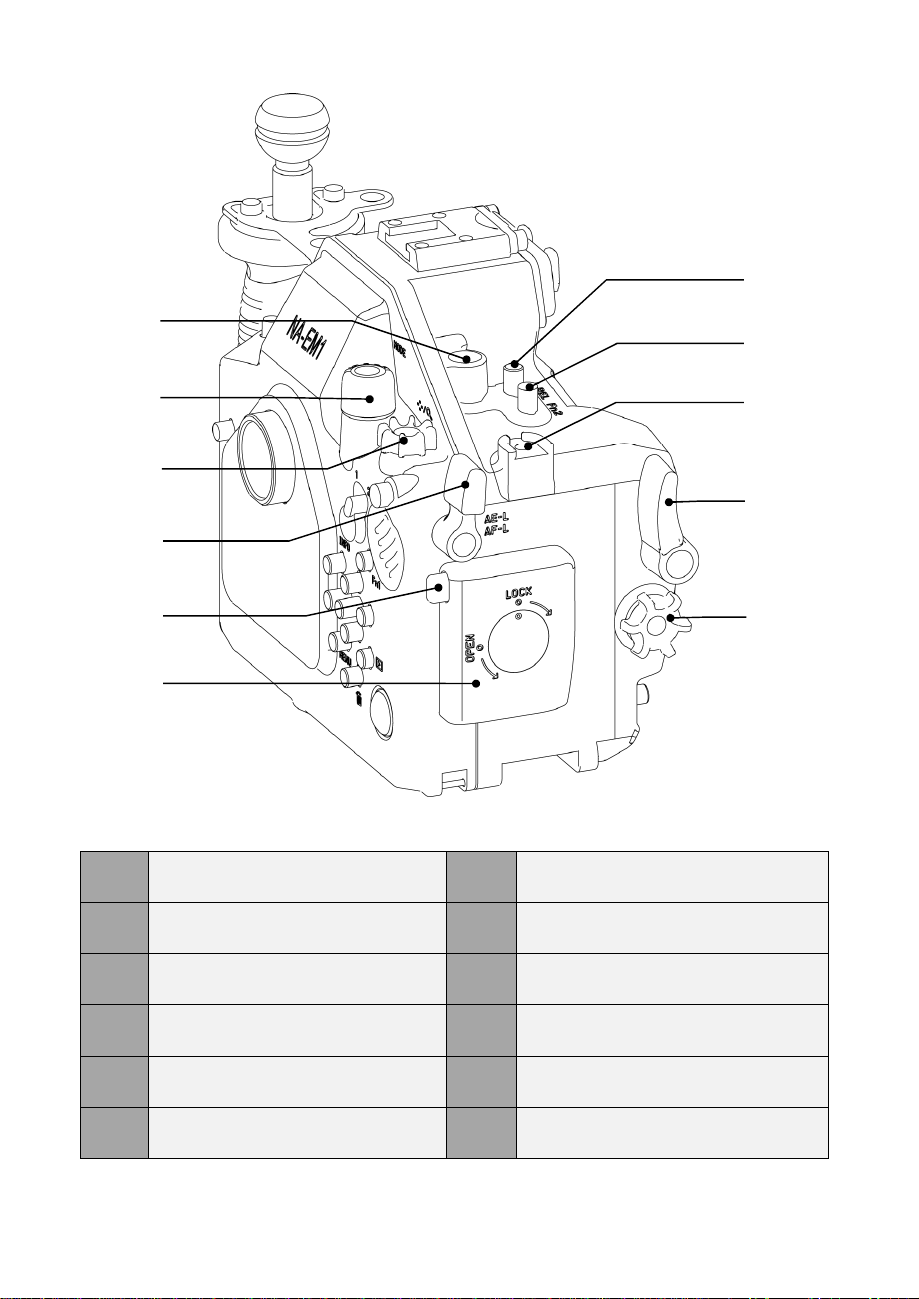
Nauticam NA-EM1 User manual
Other Nauticam Camera Accessories manuals

Nauticam
Nauticam NA-ZVE1 User manual

Nauticam
Nauticam NA-D700 User manual

Nauticam
Nauticam NA-G7X User manual

Nauticam
Nauticam N100 X1024-Z User manual

Nauticam
Nauticam 16346 User manual

Nauticam
Nauticam NA-RX100 User manual

Nauticam
Nauticam NA-EM10III User manual

Nauticam
Nauticam N100 flat port 40 User manual

Nauticam
Nauticam 19561 User manual

Nauticam
Nauticam 36207 User manual

Nauticam
Nauticam NA-A6700 User manual

Nauticam
Nauticam 26302 User manual

Nauticam
Nauticam NA-GFX100 User manual

Nauticam
Nauticam 87515 User manual

Nauticam
Nauticam M67 User manual

Nauticam
Nauticam M28C1R200-M28A1R170 User manual

Nauticam
Nauticam 36206 User manual

Nauticam
Nauticam N100 Flat Port 29 User manual

Nauticam
Nauticam NA - D780 User manual

Nauticam
Nauticam 19575 User manual


Popular Camera Accessories manuals by other brands

Viltrox
Viltrox EF-NEX Mount instructions

Calumet
Calumet 7100 Series CK7114 operating instructions

Ropox
Ropox 4Single Series User manual and installation instructions

Cambo
Cambo Wide DS Digital Series Main operating instructions

Samsung
Samsung SHG-120 Specification sheet

Ryobi
Ryobi BPL-1820 Owner's operating manual