manuals.online logo
Brands
  1. Home
  2. •
  3. Brands
  4. •
  5. Nav TV
  6. •
  7. Car Navigation System
  8. •
  9. Nav TV NTV-KIT597 User manual

Nav TV NTV-KIT597 User manual

NNG-Toyota 5
Navigation interface for select Toyota vehicles
NTV-KIT597
BHM
07/23/15
NTV-DOC226
3950 NW 120th Ave, Coral Springs, FL 33065 TEL 561-955-9770 FAX 561-955-9760
BHM
07/23/15
NTV-DOC226
Agreement: End user agrees to use this product in compliance with all State and Federal laws. NAV-TV Corp. would not be held liable for misuse of its product.
If you do not agree, please discontinue use immediately and return product to place of purchase. This product is intended for off-road use and passenger
entertainment only.
2 | P a g e
Overview
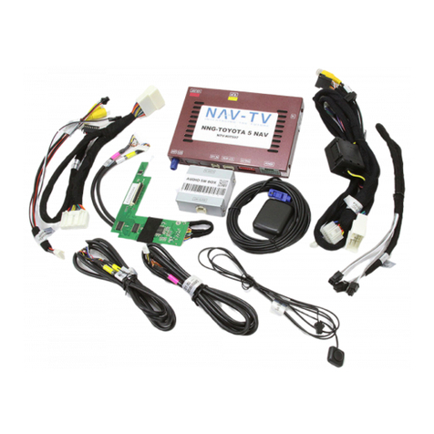
The NNG-Toyota 5 kit interfaces the widely-used Nav N GO© powered navigation system into select Toyota
OEM media systems. Disassembly of the factory Toyota LCD is required and it is recommended that only a
professional attempts this install. All factory Toyota touch functions are used for the navigation control.
Additionally, this interface allows for a backup camera to be added with no additional parts.
Kit Content
Year
Vehicle
Radio
2014-2015
Corolla, Rav4
Non-Apps, Fujitsu Ten, 6.1”
2014
Camry
Non-Apps, Fujitsu Ten, 6.1”
1. Toyota 5 GPS/Interface
2. Toyota 5 internal Modification PCB with Y-adapter
3. Audio Switching module
4. Toyota 5 Plug & Play T-Harness
5. Toyota 5 secondary Plug & Play T-Harness
6. Rear-LCD Harness
7.
TP and LCD Harnesses
8.
Optional NAV/OEM switch
9.
Audio In/Out Y-Adapter
10.
GPS Antenna
1
2
3
4
5
6
7
8
9
10
Compatibility for NNG-Toyota 5
BHM
07/23/15
NTV-DOC226
Agreement: End user agrees to use this product in compliance with all State and Federal laws. NAV-TV Corp. would not be held liable for misuse of its product.
If you do not agree, please discontinue use immediately and return product to place of purchase. This product is intended for off-road use and passenger
entertainment only.
3 | P a g e
Dash Removal (Corolla)
1. Using a plastic tool, pry the dashboard
surround beginning near the radio, it is
held in with clips only.
2. Remove (4x) 10mm bolts securing the radio. Pop out the ABS light and reconnect to avoid tripping an
AirBag Light.
BHM
07/23/15
NTV-DOC226
Agreement: End user agrees to use this product in compliance with all State and Federal laws. NAV-TV Corp. would not be held liable for misuse of its product.
If you do not agree, please discontinue use immediately and return product to place of purchase. This product is intended for off-road use and passenger
entertainment only.
4 | P a g e
Radio Modification
Bring the radio to a work bench for disassembly. Make sure you’re working in a clean area to avoid scratching
the radio face (an ESD mat is preferred but even clean carpet would be better than nothing)
1. Remove any bracketry which secured the radio to the vehicle sub dash and set them aside.
2. On the bottom of the radio, remove (2x) Phillips head screws.
3. Remove (3x) screws, and the metal plate which will expose 2 FFC connectors.
BHM
07/23/15
NTV-DOC226
Agreement: End user agrees to use this product in compliance with all State and Federal laws. NAV-TV Corp. would not be held liable for misuse of its product.
If you do not agree, please discontinue use immediately and return product to place of purchase. This product is intended for off-road use and passenger
entertainment only.
5 | P a g e
4. Gently pry up the FFC
connectors with a small flat
heat or finger nail and
remove the ribbons from 1
side (radio side). Using a
small flat head, pry the clips
up all the way around the
radio. With the clips and
ribbons free, the screen will
detach from the rest of the
radio.
5. Observe the area (on the screen) shown below. These 2 ribbons will need to be intercepted with the
provided Modification PCB. With a small flathead, pry the connectors outwards (not upwards -
towards the ribbons themselves) from the corners.
BHM
07/23/15
NTV-DOC226
Agreement: End user agrees to use this product in compliance with all State and Federal laws. NAV-TV Corp. would not be held liable for misuse of its product.
If you do not agree, please discontinue use immediately and return product to place of purchase. This product is intended for off-road use and passenger
entertainment only.
6 | P a g e
6. Remove (2x)
factory screws
shown here:
7. Replace the screw
circled in yellow
with the half-inch
stand off (provided):
8. Grab the provided Modification PCB. Face the PCB like shown below and insert the wide brown ribbon
(from the LCD panel) into the provided FFC connector. Note: the FFC connector must be released
(perpendicular to the PCB) in order for the ribbon to insert all the way. Be certain the ribbon is
inserted fully and squarely, and clamp down the tab gently.
BHM
07/23/15
NTV-DOC226
Agreement: End user agrees to use this product in compliance with all State and Federal laws. NAV-TV Corp. would not be held liable for misuse of its product.
If you do not agree, please discontinue use immediately and return product to place of purchase. This product is intended for off-road use and passenger
entertainment only.
7 | P a g e
9. Once the Brown screen ribbon is connected, gently lay the Modification PCB down like shown below.
The metal tab from the radio must pass through the hole on the PCB (circled, yellow). Use the
provided screw to secure the PCB to the stand-off (from step 7, circled in white below) and the OEM
screw for the other mounting location (circled, red).
10. Connect the OEM touch-ribbon to the provided Modification PCB like shown below (A). Then connect
the smaller white ribbon to the OEM Toyota radio FFC connector as shown (B). Pins should face down
on both.
This image shows the radio
reversed from the last image.
A
B
BHM
07/23/15
NTV-DOC226
Agreement: End user agrees to use this product in compliance with all State and Federal laws. NAV-TV Corp. would not be held liable for misuse of its product.
If you do not agree, please discontinue use immediately and return product to place of purchase. This product is intended for off-road use and passenger
entertainment only.
8 | P a g e
11. Connect the provided screen ribbon from the Modification PCB to the OEM Toyota PCB. The
connectors face each other, pins need to face down for both sides, you should see blue on both ends.
Be certain the ribbon is inserted fully and squarely.
12. Using tin-snips, cut a 1” notch in the plate remove from step 3. Lay some cloth tape around any jagged
edges for extra protection.
BHM
07/23/15
NTV-DOC226
Agreement: End user agrees to use this product in compliance with all State and Federal laws. NAV-TV Corp. would not be held liable for misuse of its product.
If you do not agree, please discontinue use immediately and return product to place of purchase. This product is intended for off-road use and passenger
entertainment only.
9 | P a g e
13. If the provided LCD/TP Y-adapter was removed from the Modification PCB, reconnect it to the board
now, metal pins must face up towards you. This connector is keyed and should only be connected in
one orientation (note small square blocks on corners). The other end of this LCD/TP Y cable must run
out through the radio chassis via the notch cut in the metal plate from step 12 (follows the ribbons).
14. If the metal tab circled below pushes on the Modification
PCB while reconnecting the LCD to the radio, cut it off
with tin snips for complete clearance:
Modification
PCB
TP/LCD
Y-Cable
Left side
of radio
BHM
07/23/15
NTV-DOC226
Agreement: End user agrees to use this product in compliance with all State and Federal laws. NAV-TV Corp. would not be held liable for misuse of its product.
If you do not agree, please discontinue use immediately and return product to place of purchase. This product is intended for off-road use and passenger
entertainment only.
10 | P a g e
15. Reconnect the ribbons previously removed in step 4.
Place the notched-plate down and secure with the
(3x) OEM screws. The TP and LCD cable should now be
free outside of the radio like shown.
16. The Toyota 5 GPS interface can be secured with
double-sided tape or Velcro to the bottom of
the radio if desired. Adjust dip switches before
this step, be sure to check for reverse camera
functionality if added, or factory. See dip switch
1 settings.
17. Make all plug & play connections on the next page. Some notes:
a. All T-Harnesses connect at the radio.
b. Be certain all connectors are connected the proper direction. All connectors are keyed and only properly
fit in one direction –although they can be forced in the wrong direction, DO NOT force a plug into a
connector, they should connect together easily.
c. 6 different connections must happen for audio from the NAV guidance to pass properly. Do not forget
to connect the red & black ‘speaker’ connection from the REAR LCD Harness (REAR LCD harness must
connect to the GPS interface, even if the momentary button is not used).
d. Refer to page 12 for DIP SWITCH settings.
BHM
07/23/15
NTV-DOC226
Agreement: End user agrees to use this product in compliance with all State and Federal laws. NAV-TV Corp. would not be held liable for misuse of its product.
If you do not agree, please discontinue use immediately and return product to place of purchase. This product is intended for off-road use and passenger
entertainment only.
11 | P a g e
BHM
07/23/15
NTV-DOC226
Agreement: End user agrees to use this product in compliance with all State and Federal laws. NAV-TV Corp. would not be held liable for misuse of its product.
If you do not agree, please discontinue use immediately and return product to place of purchase. This product is intended for off-road use and passenger
entertainment only.
12 | P a g e
Toyota 5 Dip Switch Settings
FAQ
Power
GPS Module has (2) LEDs as indicators when system is powered on. Both led lights should lit with good power. If either
LED is dimmed or off, check for B+ and ACC power sources in main interface connector (red, yellow).
Display
No Display
1. There are two led lights at the GPS module to indicate data and power. If led lights are OFF and radio is ON, check the
power fuse inside the black box from the main harness
2. Check all wiring connectors for any loose connection
3. Check all wiring shielding for any damage during the installation process
4. Check all wiring for any type of damage
5. Check Modification PCB ribbon cables for loose, misalignment, or damage
No Touch Response
1. Check both Radio mode and NAV mode for touch responses
2. Check led lights for power and data indications
3. Check Y-Cable TP/LCD IN cable for any loose connection, or damage
4. Check PCB ribbon cables for loose, misalignment, or damage
No GPS software loaded, touch screen alignment screen occurred
Check map SD card at GPS module, see any sign of missing, loose, pop-out, misalignment, or damage
Sound
1. Check all cable for connections to Audio Box for loose, or damage
2. Check software volume settings, ensure volume is not muted
3. Check connections at radio for loose, damaged wires
Dip SW:
1
2
3
4
5
6
7
8
UP
OEM RVC
X
X
X
X
X
X
DOWN
Aftermarket RVC
X

Other manuals for NTV-KIT597

1

Other Nav TV Car Navigation System manuals

Nav TV NTV-KIT607 NNG-Toyota 2 User manual

Nav TV

Nav TV NTV-KIT607 NNG-Toyota 2 User manual

Nav TV OPV-1A3G User manual

Nav TV

Nav TV OPV-1A3G User manual
Nav TV NTV-KIT596 User manual

Nav TV

Nav TV NTV-KIT596 User manual

Nav TV NTV-KIT625 User manual

Nav TV

Nav TV NTV-KIT625 User manual

Nav TV VOLVO-CAM17 User manual

Nav TV

Nav TV VOLVO-CAM17 User manual

Nav TV NTV-KIT597 User manual

Nav TV

Nav TV NTV-KIT597 User manual

Nav TV A3/GOLF 7-CAM User manual

Nav TV

Nav TV A3/GOLF 7-CAM User manual

Nav TV NNG-GM2 NTV-KIT552 User manual

Nav TV

Nav TV NNG-GM2 NTV-KIT552 User manual

Nav TV NTV-KIT604 User manual

Nav TV

Nav TV NTV-KIT604 User manual

Nav TV RGB PCM3.1 Kit User manual

Nav TV

Nav TV RGB PCM3.1 Kit User manual

Nav TV NNG-Toyota 4s NTV-KIT605 User manual

Nav TV

Nav TV NNG-Toyota 4s NTV-KIT605 User manual

Nav TV NTV-KIT581 User manual

Nav TV

Nav TV NTV-KIT581 User manual

Nav TV OPV-1LR User manual

Nav TV

Nav TV OPV-1LR User manual

Nav TV NNG-Toyota 1 NTV-KIT583 User manual

Nav TV

Nav TV NNG-Toyota 1 NTV-KIT583 User manual

Nav TV NNG-Honda 8 NTV-KIT582 User manual

Nav TV

Nav TV NNG-Honda 8 NTV-KIT582 User manual

Nav TV DIFF CAM-Switcher Manual

Nav TV

Nav TV DIFF CAM-Switcher Manual

Nav TV NTV-KIT553 User manual

Nav TV

Nav TV NTV-KIT553 User manual

Nav TV NTV-KIT589 User manual

Nav TV

Nav TV NTV-KIT589 User manual
Nav TV NTV-KIT558 User manual

Nav TV

Nav TV NTV-KIT558 User manual
Nav TV NNG-HONDA C NTV-KIT599 User manual

Nav TV

Nav TV NNG-HONDA C NTV-KIT599 User manual

Nav TV NTX-54 User manual

Nav TV

Nav TV NTX-54 User manual
Nav TV NNG-GM2 2016 User manual

Nav TV

Nav TV NNG-GM2 2016 User manual

Nav TV NNG-Honda 3 User manual

Nav TV

Nav TV NNG-Honda 3 User manual

Nav TV SIR-PCM3 955 User manual

Nav TV

Nav TV SIR-PCM3 955 User manual

Popular Car Navigation System manuals by other brands
Kenwood KNA-DV2100 instruction manual

Kenwood

Kenwood KNA-DV2100 instruction manual

Alpine X703D-A Supplement owner's manual

Alpine

Alpine X703D-A Supplement owner's manual

TomTom GO reference guide

TomTom

TomTom GO reference guide

TomTom Mazda NB1 reference guide

TomTom

TomTom Mazda NB1 reference guide

Magellan RoadMate 1400 - Automotive GPS Receiver Manual de usuario

Magellan

Magellan RoadMate 1400 - Automotive GPS Receiver Manual de usuario

Mapmyindia TrailBlazer 2 user manual

Mapmyindia

Mapmyindia TrailBlazer 2 user manual

BMW iDrive owner's manual

BMW

BMW iDrive owner's manual

Garmin ecoRoute ESP instructions

Garmin

Garmin ecoRoute ESP instructions

Simrad MX510 Quick reference guide

Simrad

Simrad MX510 Quick reference guide

Pioneer AVIC-D3 - Navigation System With DVD Player Operation manual

Pioneer

Pioneer AVIC-D3 - Navigation System With DVD Player Operation manual

Kenwood DNX892 quick start guide

Kenwood

Kenwood DNX892 quick start guide

Holux GPSmile52 Specifications

Holux

Holux GPSmile52 Specifications

Mercedes-Benz COMAND Operator's manual

Mercedes-Benz

Mercedes-Benz COMAND Operator's manual

Alpine X009 Quick reference guide

Alpine

Alpine X009 Quick reference guide

Toyota 2009 4Runner Quick reference guide

Toyota

Toyota 2009 4Runner Quick reference guide

TomTom GO user manual

TomTom

TomTom GO user manual

Rosen DS-UN0810 quick start guide

Rosen

Rosen DS-UN0810 quick start guide

Lexus ES 250 installation instructions

Lexus

Lexus ES 250 installation instructions

manuals.online logo
manuals.online logoBrands
  • About & Mission
  • Contact us
  • Privacy Policy
  • Terms and Conditions

Copyright 2025 Manuals.Online. All Rights Reserved.