Neilsen CT2206 User manual

100LB WALK BEHIND SPREADER CT2206
Instruction & Assembly
SAVE THESE INSTRUCTIONS FOR FUTURE REFERENCE

- 2 -
EC DECLARATION OF CONFORMITY
We CANNON TOOLS LTD
20 Station road, Rowley Regis, West Midlands,B65 0JU.U.K.
Declare that the following machine complies with the appropriate basic safety
and health requirements of the EC Directive based on its design and type, as
brought into circulation by us.
In case of alteration of the machine, not agreed upon by us, this declaration will
lose its validity.
Product description: WALK BEHIND SPREADER
Model: CT2206
Applicable EC Directives:
EC Machinery Directive 2006/42/EC
20 Station Road, Rowley Regis, West Midlands, B65 0JU.U.K.
Mr. Gurcharan Tony Singh Sanghera
Managing Director
CANNON TOOLS LTD
2016-01-18

- 3 -
Table of Contents
General Warnings and Rules ................................................................................3
Hazard Signal Word Definitions.............................................................................4
Controls and Features Identification......................................................................5
Component & Hardware........................................................................................6
Assembly Instructions ..............................................................................7, 8, 9 10
Operation Instructions...................................................................................11, 12
Spreading Instructions.........................................................................................13
Maintenance and Storage ...................................................................................14
Specification........................................................................................................15
Parts Drawing & Parts List........................................................................16, 17,18

- 4 -
GENERAL WARNINGS
READ and UNDERSTAND this manual completely before using Push Spreader.
Operator must read and understand all safety and warning information, operating instructions,
maintenance and storage instructions before operating this equipment. Failure to properly operate and
maintain the push spreader could result in serious injury to the operator or bystanders.
Operation Warnings
zDo not at any time carry passengers sit or stand on the spreader.
zDo not allow children to play on, stand upon or climb in the spreader.
zAlways inspect the spreader before using to assure it is in good working condition.
zReplace or repair damaged or worn parts immediately.
zAlways check and tighten hardware and assembled parts before operation.
zDo not exceed equipment maximum load capacity of 100lb.
zAvoid large holes and ditches when transporting loads.
zBe careful when operating on steep grades (hill) the spreader may tip over.
zDo not push close to creeks, ditches and public highways.
zDo not use spreader on windy days when spreading grass seed or herbicides.
zAlways use caution when loading and uploading spreader.
zNever tow the spreader with a motorized vehicle.
.
Crush and Cut Hazards
zAlways keep hands and feet clear from moving parts while operating the equipment.
zAlways clear and keep work area clean when operating.
zAlways wear safety gear, eye protection, gloves and work boots when operating the spreader.
. WARNING
The warnings, cautions, and instructions outlined in this instruction manual cannot cover all
possible conditions or situations that may occur. It must be understood by the operator that
common sense and caution are factors which cannot be built into this product and must be supplied
by the operator.
PROP 65 WARNING
This product contains chemicals known to the state of California to cause cancer, birth defects, or
other reproductive harm.
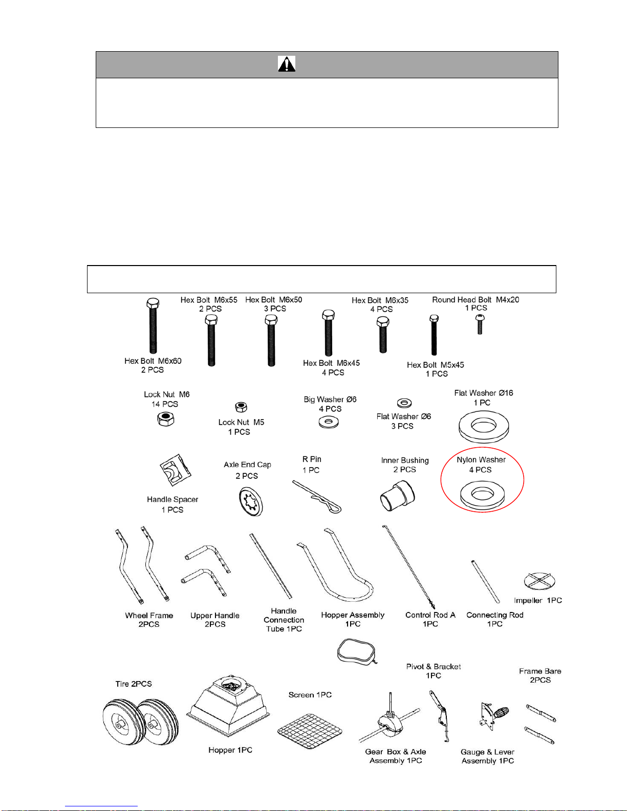
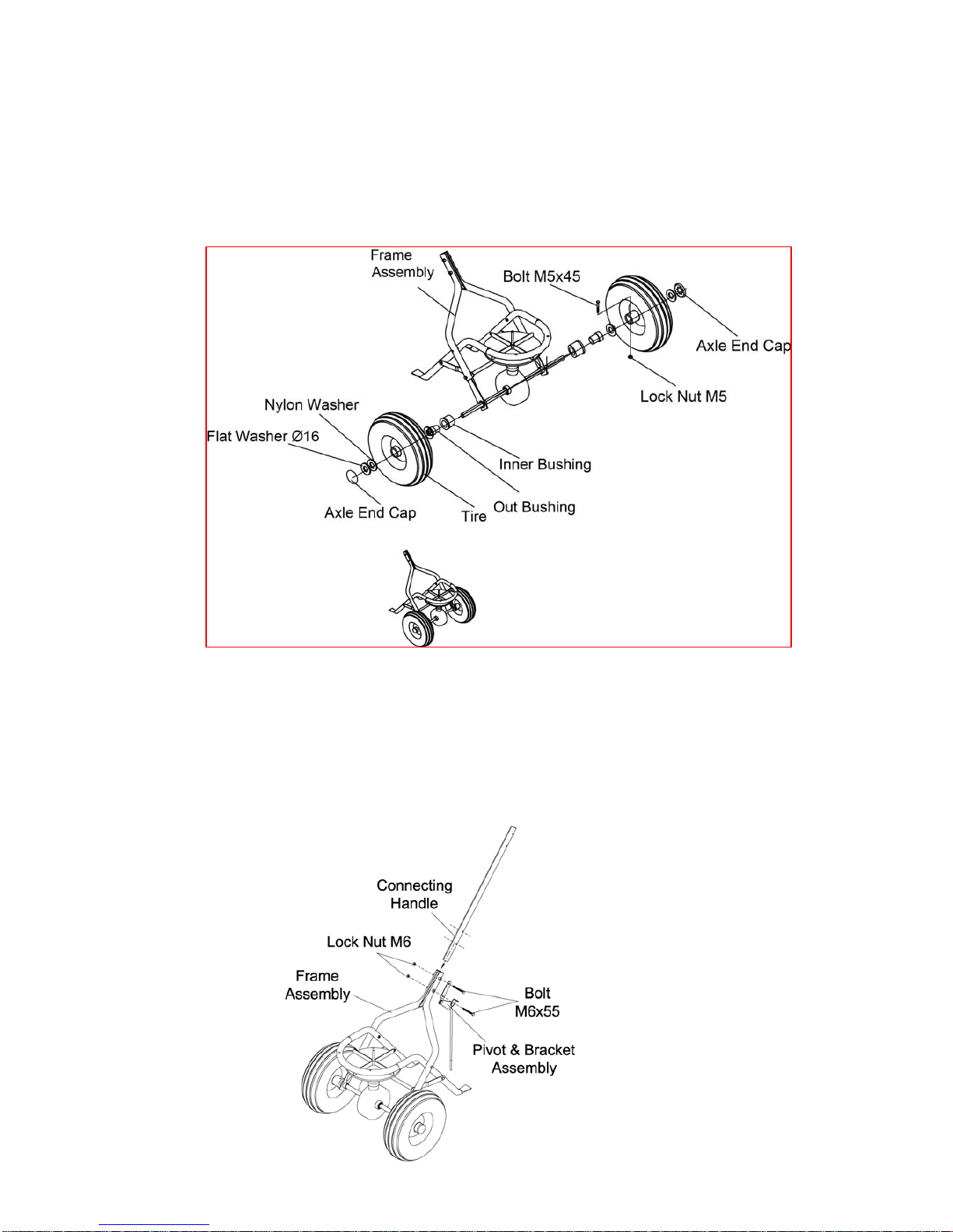
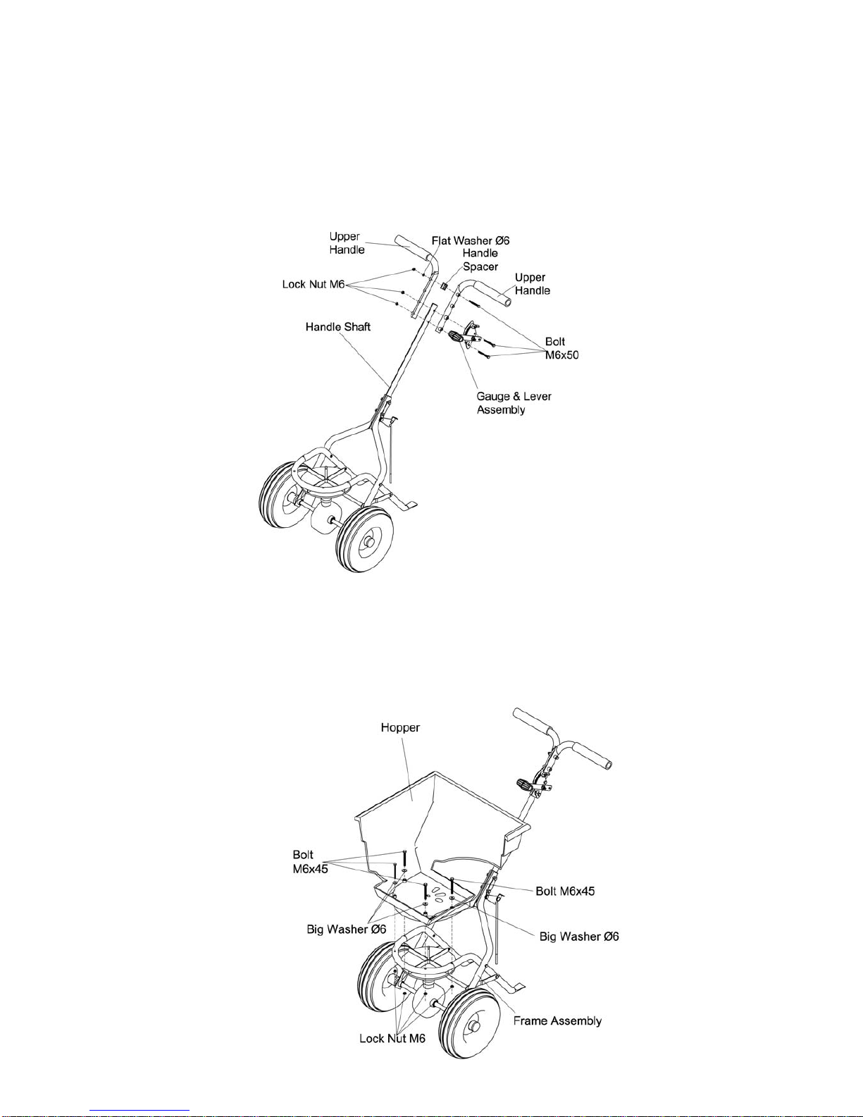
Assembly Is Required
This product requires assembly before use. See “Assembly” section for instructions. Because of the
weight and size of the push spreader, it is recommended that another adult be present to assist with
the assembly. INSPECT ALL COMPONENTS closely upon receipt to make sure no components are
missing or damaged.
.

- 5 -
Hazard Signal Word Definitions
ABOUT YOUR PUSH SPREADER
This push spreader is designed to spreader a wide range of materials (Fertilizer and Grass Seed).
Materials such as Powders, Manure, Top Soil, Gravel, and Mulch have the wrong physical characteristics
and should not be used with this spreader. Never exceed the rated load capacity of 100lbs when
operating the spreader.
Your spreader needs to be pushed at three miles per hour, which is a brisk walking speed. Slower or faster
speeds will change the spread patterns. Wet spreading material will also change the spread pattern and
flow rate. Clean your spreader thoroughly after each use. Wash between the shut off plate and bottom of
the hopper.
Ensure that the FRONT of the gear box points to the front of the spreader. The impeller must turn
clockwise. Reversing the gear box will cause the impeller to turn counter clockwise. Clean the impeller
plate after each use. Spreading material stuck on the impeller blades will cause uneven spreading.
Do not open the gear box or dirt may enter these gears are permanently lubricated at the factory.
Technical specifications on the push spreader are provided in the “Specifications” section of this manual.
This is the safety alert symbol. It is used to alert
you to potential personal injury hazards. Obey all
safety messages that follow this symbol to avoid
possible injury or death.
DANGER indicates an imminently hazardous
situation which, if not avoided, will result in death
or serious injury.
DANGER
WARNING indicates a potentially hazardous
situation which, if not avoided, could result in
death or serious injury.
WARNING
CAUTION indicates a potentially hazardous
situation which, if not avoided, may result in minor
or moderate injury.
CAUTION
CAUTION used without the safety alert symbol
indicates a potentially hazardous situation which,
if not avoided, may result in property damage.
CAUTION

- 6 -
Read this owner’s manual before operating the equipment. Familiarize yourself with the location and
function of the controls and features. Save this manual for future reference.
1) Handle – Pushes and moves the spreader easily.
2) Flow Control – Controls the flow of material being spread.
3) Hopper – Do not exceed rated load capacity 100lb.
4) Tires / Wheel – Do not exceed recommended rated 25 PSI.
5) Impeller - Evenly distributes material.
6) Support Leg – Stabilizes load and spreader.
Controls and Features Identification
1
2
3
4
5
6

- 7 -
CAUTION
Read and follow all instructions for assembly and operation. Failure to properly assemble this
equipment could result in serious injury to the user or bystanders, or cause equipment damage.
PUSH SPREADER COMPONENT PARTS AND ASSEMBLE.
Take all parts out of the shipping crate and inspect components to ensure there are no missing pieces
before starting to assemble the push spreader follow steps 1 through 8.
TOOLS REQUIRED
•Rubber Hammer
•8mm Wrench
•10mm Wrench
•Phillips Screwdriver
Rain Cove
r
1PC
Component Parts

- 8 -
STEP 1: Install impeller onto the Gear Box
1. Insert Screw M4x20 through impeller then through gear box axle.
STEP 2: Install Wheel Assembly Frame on the Gear Box
1. Make sure the hole on axle of gear box is on the right side of the assembly as shown below. Attach
one end of frame brace to hopper frame assembly using bolts M6x35 and lock nuts M6.
2. Insert two bolts M6x35 into the connecting cross rod through the wheel assembly frames and
frame braces. Insert bolts M6x60 through the wheel assembly frames onto hopper frame
assembly, put on lock nuts M6 and loosely tighten.
Assembly Instructions
Bolt M6x35

- 9 -
STEP 3: Insert Inner Axle Bushing into Outer Axle Bushing
1. Make sure everything has been tightened. Install the right tire assembly to right axle using bolt
M5x45 and lock nut M5, and then install nylon washer and end cap onto right axle using a wooden
or rubber hammer.
2. Install the left tire assembly to left axle, put a nylon washer and flat washer Ø16 and install the end
cap onto the left axle using a wooden or rubber hammer.
STEP 4: Installing Connecting Handle
1. Put the connecting handle between the two lower handles of the wheel frame assembly.
2. Attach the pivot & bracket assembly to the lower handles of the wheel frame assembly using bolts
M6x55 and lock nuts M6.
3. Tighten all nuts and bolts starting with the first step DO NOT OVER TIGHTEN.

- 10 -
STEP 5: Installing Gauge and Handle
1. Upper handle has three positions for operator comfort before installing the gauge operator needs
to determine the best.
2. Insert bolt M6X50 through both upper handles, flat washer and loosely tighten the M6 lock nut.
3. Install gauge & lever using two M6X50 bolts. Be sure the gauge is on left hand side. Tighten the
lock nuts for gauge first, and then tighten the lock nut for the upper handles in step 2.
STEP 6: Installing the Hopper
1. Lower the hopper into the frame assembly, carefully line up the hole in the bottom of the hopper
with the frame.
2. Using four hex bolts M6 x 45 and four washers, fasten the hopper to the frame by passing the bolts
through the hopper and mounting tube. Secure with lock M6 nuts.

- 11 -
STEP 7: Installing Control Rod
1. Push the handle gauge to the lowest position and insert the upper end of control rod into the hole
on the adjustable handle.
2. Remove one of nuts from threaded pole and insert the nut through the hole of pivot & bracket and
threaded pole and tighten.
3. Insert the threaded pole of adjustable pole B into the hole of adjustable plate, and then put the lock
nut M6 and flat washer Ø6.
4. Insert R Pin into the hole of turning axle at the bottom of hopper as shown.
STEP 8: Hopper Adjustments
When you finished all the above steps, you may find three holes at the bottom of hopper; match the three
holes with the adjustable plate.
If the holes do not match up do the following steps, Push the handle to the lowest position <downwards>
and adjust the positions of these two nuts on threaded control bar so the three holes at the bottom of
hopper closely match the three holes of adjustable plate (must closed properly).

- 12 -
WARNING
Before using the push spreader, review the instructions below and safety information before operating.
Failure to follow these instructions may result in property damage or injury to the operator or
bystanders.
USING YOUR SPREADER
1. Inspect your spreader before each use. Make sure the wheels turn easily, and the gearbox moves
when the spreader is pushed. The hopper should be clean and free from cracks.
2. Spreader is designed to spread a range of materials (Fertilizer and Grass Seed). Materials such as
Powder, Manure, Top Soil, Gravel, and Mulch have the wrong physical characteristics and should not
be used with your spreader
3. Do not use spreader on windy days when spreading grass seed or herbicides.
4. Determine approximate square footage of the area to be covered and estimate amount of material
required. Please refer to fertilizer manufacturer’s recommendation. Break up any lumpy fertilizer as
you fill the hopper.
5. Before filling the hopper, make sure that the flow control lever is in the“0”position and the flow control
plate is closed.
6. Set the adjustable stop with the flow control lever always in the“0”position. Every time you are ready
to stop or turn back, close the flow control plate to stop dispersing the material and continue one more
stride. This reduces waste and avoids damaging the lawn with oversaturated product coverage.
7. Follow fertilizer manufacturer’s recommended coverage rate for each product
8. To maintain the same coverage when walking at a different speed, adjust the flow rate. Reduce the
flow setting for slower speeds and increase the flow setting for higher speeds.
9. Keep the impeller plate horizontal when operating the spreader. Tilting the spreader will result in
uneven coverage.
10. Make sure the R pin is installed in the hopper before starting the spreader.
11. Always start walking prior to opening the closure plate.
12. Always close the flow control plate before turning or stopping the spreader.
13. If spreading material is accidentally deposited too heavily in a small area, soak the area thoroughly
with a garden hose or sprinkler to prevent burning of the lawn.
14. To insure consistent coverage, make sure each broadcast pattern slightly overlaps the previous
broadcast pattern.
15. When broadcasting spreading material, make sure the broadcast pattern does not hit evergreen trees,
flowers or shrubs.
16. Do not over apply spreading material. Follow the recommended coverage rate for each product. Over
application will lead to lawn damage and contamination.
Operation Instructions

- 13 -
ADJUSTING THE FLOW
1. Push the handle to the top position (upwards). Move the position of the wing nut on the gauge &
lever to adjust the three holes between hopper and adjustable plate when spreading material.
CONSISTENT COVERAGE
To insure consistent coverage, make sure each broadcast pattern slightly overlaps the previous broadcast
pattern as shown in figure below for large particles. The approximate broadcast widths for different size
materials are shown in Chart B.
WARNING
Do not over apply spreading material. Follow the recommended coverage rate for each product. Over
application will lead to damage and contamination. If spreading material accidentally hits or deposits
too heavily, soak the area thoroughly with a garden hose or sprinkler to prevent chemical burning.
Operation Instructions

- 14 -
CALCULATING AMOUNT OF MATERIAL NEEDED
To calculate the amount of fertilizer you will need to cover your lawn, divide the coverage amount listed on
the label by the weight of the fertilizer bag. For example a 10LB. bag of fertilizer with coverage of 10,000
square feet will distribute 1LB. of fertilizer every 1,000 square feet at full rate or 1/2LB. of fertilizer every
1,000 square feet at half rate. For pre-calculated rates see Chart A (Example: 25LB. bag with 15,000 sq. ft.
coverage = 1.7LB./1,000 sq. ft.). Use Chart B to find the closest spreader setting (Example: 1.7LB./1000
sq. ft. = Spreader Setting of 5).
Chart A - Square Foot Coverage per Bag*
LBS/1,000 SQ FT
Weight of Bag (LBS.) 5,000 SQ FT COVERAGE 10,000 SQ FT COVERAGE 15,000 SQ FT COVERAGE
5 1.0 LB. 0.5 LB. 0.3 LB.
10 2.0 LB. 1.0 LB. 0.7 LB.
15 3.0 LB. 1.5 LB. 1.0 LB.
20 4.0 LB. 2.0 LB. 1.3 LB.
25 5.0 LB. 2.5 LB. 1.7 LB.
30 6.0 LB. 3.0 LB. 2.0 LB.
35 7.0 LB. 3.5 LB. 2.3 LB.
40 8.0 LB. 4.0 LB. 2.7 LB.
45 9.0 LB. 4.5 LB. 3.0 LB.
50 10.0 LB. 5.0 LB. 3.3 LB.
*These are only estimates actual amounts may vary.
Chart B - Spreader Settings/Spread Widths
MULTI-
USAGES LBS/1,000
SQ FT SPREADER
SETTING
•
SMALL
PARTICLE
SPREAD
•
MEDIUM
PARTICLE
SPREAD
•
LARGE
PARTICLE
SPREAD
FERTILIZER
GRASS
SEEDS
1 3 5-6 FT. 6-9 FT. 9-12 FT.
2 5 5-6 FT. 6-9 FT. 9-12 FT.
3 7 5-6 FT. 6-9 FT. 9-12 FT.
4 10 5-6 FT. 6-9 FT. 9-12 FT.
5 12 5-6 FT. 6-9 FT. 9-12 FT.
6 15 5-6 FT. 6-9 FT. 9-12 FT.
7 17 5-6 FT. 6-9 FT. 9-12 FT.
8 20 5-6 FT. 6-9 FT. 9-12 FT.
9 22 5-6 FT. 6-9 FT. 9-12 FT.
10 25 5-6 FT. 6-9 FT. 9-12 FT.
NOTE: DO NOT USE SALT. Using salt in this spreader will damage the mechanism and shorten the life of the
machine.
SPREADING INSTRUCTIONS

- 15 -
WARNING
Improper maintenance and storage of the push spreader may void your warranty.
MAINTENANCE
•After each use clean material out of hopper.
•Rinse/dry inside and outside of the spreader after each use.
•Before operating make sure the tires have the RECOMMENDED TIRE PRESSURE 25 PSI.
•Periodically check all fasteners for tightness.
•Annually clean and lightly lubricate parts.
•Use a glossy enamel spray paint to touch up scratched or worn painted metal surfaces.
•Never exceed load capacity rating of 100lbs it will damage the spreader.
IMPORTANT:
If a part needs replacement, only use parts that meet the manufacturer’s specifications. Replacement
parts that do not meet specifications may result in a safety hazard or poor operations.
STORAGE
•Never allow material to remain in the hopper for extended periods of time.
•Before storing make sure the spreader is clean and dry for years of trouble free service.
•Store indoors or protected area during severe weather and winter months.
Maintenance and Storage

- 16 -
Load Capacity ................................................................................................100lb
Spreader Type.........................................................................................Broadcast
Hopper Material................................................................................Polypropylene
Hopper Dimensions......................................................................21.5” x 21.5”x14”
Overall Dimensions.....................................................................48.8”x32.1”x21.7”
Wheel size.......................................................................................................12.5”
Tire Pressure (PSI)..............................................................................................25
Unit Weight..................................................................................................25.35lb
The manufacturer reserves the right to make improvements in design and/or changes in
specifications at any time without incurring any obligation to install them on units previously
sold.
Specifications

- 17 -
Parts Drawing & Parts List

- 18 -
Ref# Drawing No. Description Qty
1 N572-00003 Handle Spacer 1
2 9114-06025-DG Carriage Bolt M6x25 1
3 9315-08000-DG Teeth Lock Washer Ø8 1
4 N570-10000 Gauge & Lever Assembly 1
5 N570-00001-DG Adjustable Handle Pole 1
6 N570-00014 Adjustable Handle A 1
7 N570-00015 Adjustable Handle B 1
8 9118-04018-DG Screw M4x18 1
9 N510-00016 Spacer 1
10 N510-00019 Wing Nut M6 1
11 9101-06045-DG Hex Bolt M6x45 4
12 C130-00004 Nylon Washer 1
13 9302-06000-DG Big Flat Washer Ø6 5
14 9101-05045-DG Hex Bolt M5x45 1
15 N570-00009 Handle Cover 2
16 N572-00001 Hopper 1
17 N570-00017-DG R Pin Ø2 1
18 N510-00004 Hopper Bushing 1
19 N572-10000 Pivot & Bracket Assembly 1
20 N570-00007 Wheel Assembly Frame 2
21 9201-06000-DG Hex Nut M6 2
22 T680-00003 End Cover 2
23 N570-00006 Upper Handle 2
24 9206-06000-DG Lock Nut M6 15
25 N570-00003-DG Control Rod A 1
26 N572-00002 Middle Connecting Handle 1

- 19 -
Ref# Drawing No. Description Qty
27 N570-00023 Shut off plate 1
28 9302-04000-DG Big Flat Washer Ø4 3
29 9118-04012-DG Screw M4x12 3
30 N572-00005 Hopper Assembly Frame 1
31 N570-00010-DG Frame Brace 2
32 9101-06050-DG Hex Bolt M6X50 3
33 9101-06035-DG Hex Bolt M6X35 4
34 9301-16000-DG Flat Washer Ø16 1
35 N511-40000-BXG End Cap 2
36 N570-00020 Tire 2
37 N570-00018 Inner Bushing 2
38 N570-00011 Outer Bushing 2
39 N570-40000 Gear Box & Axle Assembly 1
40 N570-00002 Thin Washer 1
41 9110-04020-DG Screw M4x20 1
42 N510-00003 Impeller 1
43 9301-06000-DG Flat Washer Ø6 4
44 9206-05000-DG Lock Nut M5 1
45 N570-00021-DG Connecting Cross Bar 1
46 N570-00004-DG Adjustable Connecting Rod B 1
47 9101-06060-DG Hex Bolt M6x60 2
48 N572-00004 Screen 1
49 9306-06000-DG Lock Washer Ø6 1
50 9101-06055-DG Hex Bolt M6x55 2
51 9404-02010-DG Cotter Pin 1
52 N574-00002 Rain Cover 1
53 N570-00027-000 Nylon Washer 4

- 20 -
CANNON TOOLS LTD
20 Station road, Rowley Regis, West Midlands,B65 0JU.U.K.
Made in China
Other manuals for CT2206
1
Table of contents
Other Neilsen Spreader manuals
Popular Spreader manuals by other brands

Cub Cadet
Cub Cadet 125 lb Spreader & 10 Gallon Sprayer Operator's manual

Advantech
Advantech VEGA-320 Startup manual

Swisher
Swisher 11730 owner's manual

CEMO
CEMO SW 20-P manual

Harbor Freight Tools
Harbor Freight Tools 99621 Set up and operating instructions

Scotts
Scotts Turf Builder EdgeGuard DLX quick start guide