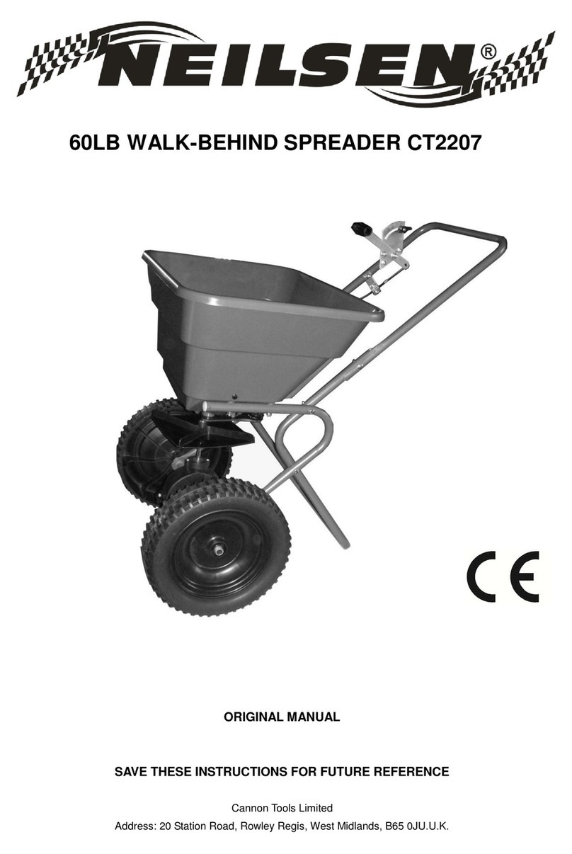
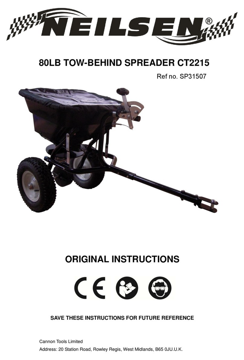
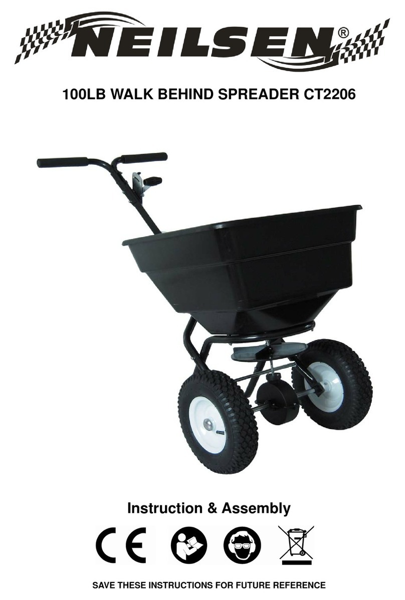
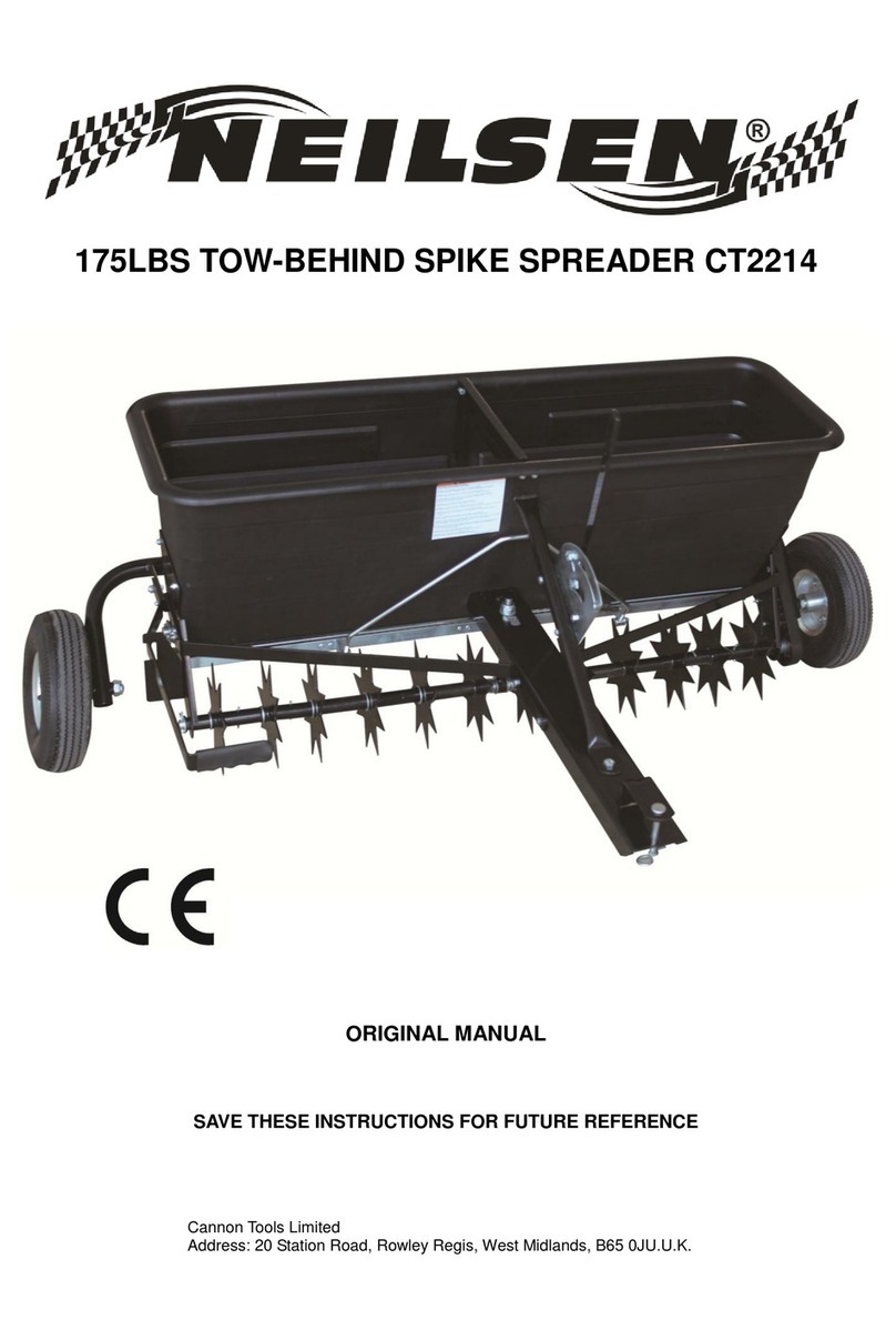
Neilsen CT2206 User manual

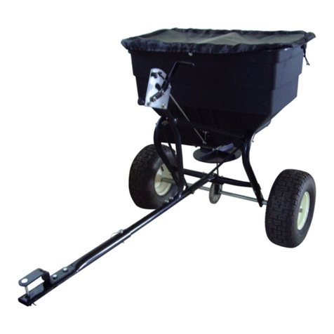
100LB WALK BEHIND SPREADER CT2206
INSTRUCTION MANUAL
SAVE THESE INSTRUCTIONS AND PRECAUTIONS.
READ ALL PRECAUTONS AND INSTRUCTIONS BEFORE USE.
Cannon Tools Limited
Address: 20 Station Road, Rowley Regis, West Midlands, B65 0JU.U.K.

1
EC DECLARATION OF CONFORMITY
We CANNON TOOLS LTD
20 Station road, Rowley Regis, West Midlands,B65 0JU.U.K.
Declare that the following machine complies with the appropriate basic safety
and health requirements of the EC Directive based on its design and type, as
brought into circulation by us.
In case of alteration of the machine, not agreed upon by us, this declaration will
lose its validity.
Product description: 100 LB WALK-BEHIND SPREADER
Model: CT2206
Applicable EC Directives:
EC Machinery Directive 2006/42/EC
Harmonized standards
EN ISO 12100:2010, EN ISO 13854:2019,
EN ISO 14120:2015, EN ISO 13857:2019
20 Station Road, Rowley Regis, West Midlands, B65 0JU.U.K.
Mr. Gurcharan Tony Singh Sanghera
Managing Director
CANNON TOOLS LTD
sign
Gurcharan Tony Singh Sanghera
2021-07-05

2
1. SPECIFICATIONS
Capacity: 100LB
Spread Width: 10'-12'/3048mm-3658mm
Plastic Tyre: 12"
Coverage: 20000 sq/ft
Heavy duty nylon gear.
Rate setting control on handle for precise adjustments.
Accessories: screen & rain cover
2. GENERAL SAFETY INSTRUCTIONS
Warning: When using tool, basic safety precautions should always be followed to
reduce the risk of personal injury and damage to equipment. Read all instructions
before using this tool!
STAY ALERT. Do not operate the machine while under the influence of drugs,
alcohol, or any medication that could affect your ability to use it properly. Do not
use this machine when you are tired or distracted from the job at hand. Be aware
of what you are doing at all times. Use common sense.
AVOID DANGEROUS CONDITIONS. Make sure there is adequate surrounding
workspace. Cluttered areas invite injuries. Keep your work area clean with
sufficient light. Keep the area around the machine clear of obstructions, grease,
oil, rubbish & other debris which could cause persons to fall onto moving
parts.
INSPECT YOUR MACHINE. Check all bolts, nuts & screws for tightness before
each use, especially those securing guards & drive mechanisms. Vibration
during use, may cause these to loosen. Replace damaged, missing or
failed parts before using. Warning labels carry important information. Replace
any missing or damaged warning labels.
CRUSH AND CUT HAZARDS. Always keep your hands and feet clear from
moving parts while operating the equipment. Always keep the work area clean
and clear when operating.

3
CONDITIONS. We recommend the machine is not used during winds. This may
affect the spreading pattern.
DRESS PROPERLY. Do not wear loose clothing, gloves, scarfs, neckties
or jewellery (rings, wrist watches), which can be caught in moving parts.
DO NOT OVERREACH. Keep proper footing and balance at all times
when using the machine. Never stand on the machine. Serious injury could occur
if the machine is tipped or if the moving parts are unintentionally contacted. Do
not store anything above or near the machine, where anyone might stand on the
machine to reach them.
AVOID INJURY FROM UNEXPECTED ACCIDENT. Keep hands & feet out of the
way of all moving parts. Do not place any part of your body or any tool e.g. in
moving parts of the machine during operation.
DO NOT FORCE TOOL. Always work within the rated capacity. Do not operate
for a purpose for which it was not intended.
MAINTAIN YOUR MACHINE WITH CARE. Clean the machine immediately after
use. Keep the machine clean to ensure it operates to its full & safest
performance. When maintaining this machine, only the manufacturer’s original
replacement parts should be used.
PROTECT THE ENVIRONMENT. Take left over materials to an authorised
collection point or follow the stipulations in the country where the machine is
used. Do not discharge into drains, soil or water.
STORE IDLE EQUIPMENT. When not in use, the machine should be stored in a
dry location. Keep the machine away from children and others not qualified to
use it.
OPERATION SPEED. Do not exceed 6 mph, to avoid personal injury and/or
equipment damage.
TYRE INFLATION. WARNING! Over-inflated tyres can explode and cause
serious injury. Avoid injury by NEVER over inflating tyres beyond the maximum
pressure printed on the side of the tyre wall. ALWAYS use FOOT or HAND pump
inflation devices.
This is a garden/domestic product, therefore extended use over abrasive
surfaces (e.g. concrete, tarmac etc.) could cause premature wear on the tyres.

4
3. CONTROLS AND FEATURES IDENTIFICATION
Read this owner’s manual before operating the equipment. Familiarize yourself
with the location and function of the controls and features. Save this manual for
future reference.
1) Handle – Pushes and moves the spreader easily.
2) Flow Control – Controls the flow of material being spread.
3) Hopper – Do not exceed rated load capacity 100lb.
4) Tires / Wheel – Do not exceed recommended rated 25 PSI.
5) Impeller - Evenly distributes material.
6) Support Leg – Stabilizes load and spreader.

5
4. ASSEMBLY AND OPERATING INSTRUCTIONS
1. HELPFUL HINTS:
READ THE INSTRUCTIONS BEFORE ASSEMBLY
This push spreader is designed to spreader a wide range of materials (Fertilizer
and Grass Seed). Materials such as Powders, Manure, Top Soil, Gravel, and
Mulch have the wrong physical characteristics and should not be used with this
spreader. Never exceed the rated load capacity of 100lbs when operating the
spreader.
Your spreader needs to be pushed at three miles per hour, which is a brisk
walking speed. Slower or faster speeds will change the spread patterns. Wet
spreading material will also change the spread pattern and flow rate. Clean your
spreader thoroughly after each use. Wash between the shut off plate and bottom
of the hopper.
Ensure that the FRONT of the gear box points to the front of the spreader. The
impeller must turn clockwise. Reversing the gear box will cause the impeller to
turn counter clockwise. Clean the impeller plate after each use. Spreading
material stuck on the impeller blades will cause uneven spreading.
Do not open the gear box or dirt may enter these gears are permanently
lubricated at the factory.
2. PUSH SPREADER COMPONENT PARTS AND ASSEMBLE.
Take all parts out of the shipping crate and inspect components to ensure there
are no missing pieces before starting to assemble the push spreader follow steps
1 through 8.
TOOLS REQUIRED
Rubber Hammer
8mm Wrench
10mm Wrench
Phillips Screwdriver

6
3. ASSEMBLY
STEP 1: Install impeller onto the Gear Box
1.Insert Screw M4x20 through impeller then through gear box axle.

7
STEP 2: Install Wheel Assembly Frame on the Gear Box
1. Make sure the hole on axle of gear box is on the right side of the assembly as
shown below. Attach one end of frame brace to hopper frame assembly using
bolts M6 x 35 and lock nuts M6.
2. Insert two bolts M6 x 35 into the connecting cross rod through the wheel
assembly frames and frame braces. Insert bolts M6x60 through the wheel
assembly frames onto hopper frame assembly, put on lock nuts M6 and loosely
tighten.
Bolt M6x35

8
STEP 3: Insert Inner Axle Bushing into Outer Axle Bushing
1. Make sure everything has been tightened. Install the right tire assembly to
right axle using bolt M5 x 45 and lock nut M5, and then install nylon washer and
end cap onto right axle using a wooden or rubber hammer.
2. Install the left tire assembly to left axle, put a nylon washer and flat washer
Ø16 and install the end cap onto the left axle using a wooden or rubber hammer.

9
STEP 4: Installing Connecting Handle
1. Put the connecting handle between the two lower handles of the wheel frame
assembly.
2. Attach the pivot & bracket assembly to the lower handles of the wheel frame
assembly using bolts M6x55 and lock nuts M6.
3. Tighten all nuts and bolts starting with the first step DO NOT OVER
TIGHTEN.

10
STEP 5: Installing Gauge and Handle
1. Upper handle has three positions for operator comfort before installing the
gauge operator needs to determine the best.
2. Insert bolt M6X50 through both upper handles, flat washer and loosely tighten
the M6 lock nut.
3. Install gauge & lever using two M6X50 bolts. Be sure the gauge is on left hand
side. Tighten the lock nuts for gauge first, and then tighten the lock nut for the
upper handles in step 2.

11
STEP 6: Installing the Hopper
1. Lower the hopper into the frame assembly, carefully line up the hole in the
bottom of the hopper with the frame.
2. Using four hex bolts M6 x 45 and four washers, fasten the hopper to the frame
by passing the bolts through the hopper and mounting tube. Secure with lock M6
nuts.

12
STEP 7: Installing Control Rod
1. Push the handle gauge to the lowest position and insert the upper end of
control rod into the hole on the adjustable handle.
2. Remove one of nuts from threaded pole and insert the nut through the hole of
pivot & bracket and threaded pole and tighten.
3. Insert the threaded pole of adjustable pole B into the hole of adjustable plate,
and then put the lock nut M6 and flat washer Ø6.
4. Insert R Pin into the hole of turning axle at the bottom of hopper as shown.

13
STEP 8: Hopper Adjustments
When you finished all the above steps, you may find three holes at the bottom of
hopper; match the three holes with the adjustable plate.
If the holes do not match up do the following steps, Push the handle to the
lowest position <downwards> and adjust the positions of these two nuts on
threaded control bar so the three holes at the bottom of hopper closely match the
three holes of adjustable plate (must closed properly).
5. OPERATING INSTRUCTIONS
WARNING!Before using the push spreader, review the instructions below and
safety information before operating. Failure to follow these instructions may
result in property damage or injury to the operator or bystanders.
USING YOUR SPREADER
1. Inspect your spreader before each use. Make sure the wheels turn easily, and
the gearbox moves when the spreader is pushed. The hopper should be clean
and free from cracks.
2. Spreader is designed to spread a range of materials (Fertilizer and Grass
Seed). Materials such as Powder, Manure, Top Soil, Gravel, and Mulch have
the wrong physical characteristics and should not be used with your spreader
3. Do not use spreader on windy days when spreading grass seed or herbicides.
4. Determine approximate square footage of the area to be covered and
estimate amount of material required. Please refer to fertilizer manufacturer’s
recommendation. Break up any lumpy fertilizer as you fill the hopper.
5. Before filling the hopper, make sure that the flow control lever is in the“0”
position and the flow control plate is closed.
6. Set the adjustable stop with the flow control lever always in the“0”position.
Every time you are ready to stop or turn back, close the flow control plate to stop
dispersing the material and continue one more stride. This reduces waste and
avoids damaging the lawn with oversaturated product coverage.
7. Follow fertilizer manufacturer’s recommended coverage rate for each product
8. To maintain the same coverage when walking at a different speed, adjust the
flow rate. Reduce the flow setting for slower speeds and increase the flow setting
for higher speeds.
9. Keep the impeller plate horizontal when operating the spreader. Tilting the

14
spreader will result in uneven coverage.
10. Make sure the R pin is installed in the hopper before starting the spreader.
11. Always start walking prior to opening the closure plate.
12. Always close the flow control plate before turning or stopping the spreader.
13. If spreading material is accidentally deposited too heavily in a small area,
soak the area thoroughly with a garden hose or sprinkler to prevent burning of
the lawn.
14. To insure consistent coverage, make sure each broadcast pattern slightly
overlaps the previous broadcast pattern.
15. When broadcasting spreading material, make sure the broadcast pattern
does not hit evergreen trees, flowers or shrubs.
16. Do not over apply spreading material. Follow the recommended coverage
rate for each product. Over application will lead to lawn damage and
contamination.
ADJUSTING THE FLOW
Push the handle to the top position (upwards). Move the position of the wing nut
on the gauge & lever to adjust the three holes between hopper and adjustable
plate when spreading material.

15
CONSISTENT COVERAGE
To insure consistent coverage, make sure each broadcast pattern slightly
overlaps the previous broadcast pattern as shown in figure below for large
particles. The approximate broadcast widths for different size materials are
shown in Chart B.
WARNING! Do not over apply spreading material. Follow the recommended
coverage rate for each product. Over application will lead to damage and
contamination. If spreading material accidentally hits or deposits too heavily,
soak the area thoroughly with a garden hose or sprinkler to prevent chemical
burning.
6. SPREADING INSTRUCTIONS
CALCULATING AMOUNT OF MATERIAL NEEDED
To calculate the amount of fertilizer you will need to cover your lawn, divide the
coverage amount listed on the label by the weight of the fertilizer bag. For
example a 10LB. bag of fertilizer with coverage of 10,000 square feet will
distribute 1LB. of fertilizer every 1,000 square feet at full rate or 1/2LB. of fertilizer
every 1,000 square feet at half rate. For pre-calculated rates see Chart A
(Example: 25LB. bag with 15,000 sq. ft. coverage = 1.7LB./1,000 sq. ft.). Use
Chart B to find the closest spreader setting (Example: 1.7LB./1000 sq. ft. =
Spreader Setting of 5).

16
Chart A - Square Foot Coverage per Bag*
LBS/1,000 SQ FT
Weight of Bag
(LBS.)
5,000 SQ FT
COVERAGE
10,000 SQ FT
COVERAGE
15,000 SQ FT
COVERAGE
5
1.0 LB.
0.5 LB.
0.3 LB.
10
2.0 LB.
1.0 LB.
0.7 LB.
15
3.0 LB.
1.5 LB.
1.0 LB.
20
4.0 LB.
2.0 LB.
1.3 LB.
25
5.0 LB.
2.5 LB.
1.7 LB.
30
6.0 LB.
3.0 LB.
2.0 LB.
35
7.0 LB.
3.5 LB.
2.3 LB.
40
8.0 LB.
4.0 LB.
2.7 LB.
45
9.0 LB.
4.5 LB.
3.0 LB.
50
10.0 LB.
5.0 LB.
3.3 LB.
*These are only estimates actual amounts may vary.
Chart B - Spreader Settings/Spread Widths
MULTI-
USAGES
LBS/1,000
SQ FT
SPREADER
SETTING
•
SMALL
PARTICLE
SPREAD
•
MEDIUM
PARTICLE
SPREAD
•
LARGE
PARTICLE
SPREAD
FERTILIZE
R
GRASS
SEEDS
1
3
5-6 FT.
6-9 FT.
9-12 FT.
2
5
5-6 FT.
6-9 FT.
9-12 FT.
3
7
5-6 FT.
6-9 FT.
9-12 FT.
4
10
5-6 FT.
6-9 FT.
9-12 FT.
5
12
5-6 FT.
6-9 FT.
9-12 FT.
6
15
5-6 FT.
6-9 FT.
9-12 FT.
7
17
5-6 FT.
6-9 FT.
9-12 FT.
8
20
5-6 FT.
6-9 FT.
9-12 FT.
9
22
5-6 FT.
6-9 FT.
9-12 FT.
10
25
5-6 FT.
6-9 FT.
9-12 FT.
NOTE: DO NOT USE SALT. Using salt in this spreader will damage the mechanism and
shorten the life of the machine.

17
7. MAINTENANCE AND STORAGE
MAINTENANCE
● After each use clean material out of hopper.
● Rinse/dry inside and outside of the spreader after each use.
● Before operating make sure the tires have the RECOMMENDED TYRE
PRESSURE .
● Periodically check all fasteners for tightness.
● Annually clean and lightly lubricate parts.
● Use a glossy enamel spray paint to touch up scratched or worn painted metal
surfaces.
● Never exceed load capacity rating of 100lbs it will damage the spreader.
IMPORTANT:
If a part needs replacement, only use parts that meet the manufacturer’s
specifications. Replacement parts that do not meet specifications may result in a
safety hazard or poor operations.
STORAGE
● Never allow material to remain in the hopper for extended periods of time.
● Before storing make sure the spreader is clean and dry for years of trouble free
service.
● Store indoors or protected area during severe weather and winter months.

18
8. PARTS DRAWING

19
PARTS LIST
Ref#
Description
Qty
Ref#
Description
Qty
1
Handle Spacer
1
28
Big Flat Washer Ø4
3
2
Carriage Bolt M6x25
1
29
Screw M4x12
3
3
Teeth Lock Washer Ø8
1
30
Hopper Assembly Frame
1
4
Gauge & Lever Assembly
1
31
Frame Brace
2
5
Adjustable Handle Pole
1
32
Hex Bolt M6X50
3
6
Adjustable Handle A
1
33
Hex Bolt M6X35
4
7
Adjustable Handle B
1
34
Flat Washer Ø16
1
8
Screw M4x18
1
35
End Cap
2
9
Spacer
1
36
Tire
2
10
Wing Nut M6
1
37
Inner Bushing
2
11
Hex Bolt M6x45
4
38
Outer Bushing
2
12
Nylon Washer
1
39
Gear Box & Axle Assembly
1
13
Big Flat Washer Ø6
5
40
Thin Washer
1
14
Hex Bolt M5x45
1
41
Screw M4x20
1
15
Handle Cover
2
42
Impeller
1
16
Hopper
1
43
Flat Washer Ø6
4
17
R Pin Ø2
1
44
Lock Nut M5
1
18
Hopper Bushing
1
45
Connecting Cross Bar
1
19
Pivot & Bracket Assembly
1
46
Adjustable Connecting Rod B
1
20
Wheel Assembly Frame
2
47
Hex Bolt M6x60
2
21
Hex Nut M6
2
48
Screen
1
22
End Cover
2
49
Lock Washer Ø6
1
23
Upper Handle
2
50
Hex Bolt M6x55
2
24
Lock Nut M6
15
51
Cotter Pin
1
25
Control Rod A
1
52
Rain Cover
1
26
Middle Connecting Handle
1
53
Nylon Washer
4
27
Shut off plate
1
CANNON TOOLS LTD
Add: 20 station road, Rowley Regis, west midlands,B65 0JU.U.K.
Made in China
Other manuals for CT2206
1
Table of contents
Other Neilsen Spreader manuals
Popular Spreader manuals by other brands

BAUMAN
BAUMAN 440E Operator's manual

Chapin
Chapin 82108N Assembly / operation instructions / parts

EINHELL
EINHELL 3415411 Original operating instructions

Holmatro
Holmatro Pentheon Series manual

Glasdon
Glasdon ICEMASTER 50 Instruction leaflet

Douglas Dynamics
Douglas Dynamics SnowEx HELIXX 1.5 yd3 installation instructions

Nogueira
Nogueira ROTAFLOW-1300 instruction manual

Trynex
Trynex SnowEx PWX-200 Onwer / Operator's Manual

SnowEx
SnowEx SP-2200 Operator's manual

PermaGreen Supreme
PermaGreen Supreme MAGNUM SmartSteer C3C 2009 Operator's manual

SPYKER
SPYKER SPY50L-2S Operator's manual

Brinly-Hardy
Brinly-Hardy Spyker Spreaders ROS 6 quick start guide