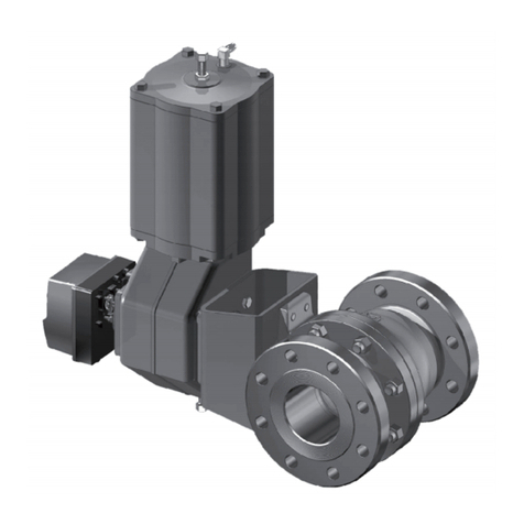
Neles Metso T2 Series Operating and maintenance manual

1 T 70 en • 12/2008
TOP ENTRY BALL VALVE
Series T2
Installation, Maintenance and
Operating Instructions

21 T 70 en
READ THESE INSTRUCTIONS FIRST!
These instructions provide information about safe handling and operation of the valve.
If you require additional assistance, please contact the manufacturer or manufacturer's representative.
Addresses and phone numbers are printed on the back cover.
SAVE THESE INSTRUCTIONS!
Subject to change without notice.
All trademarks are property of their respective owners.
Table of Contents
1 GENERAL........................................................ 3
1.1 Scope of the manual..............................3
1.2 Valve description....................................3
1.3 Valve markings.......................................3
1.4 Technical specifications.........................3
1.5 Valve certifications.................................4
1.6 CE marking ............................................4
1.7 Recycling and disposal ..........................4
1.8 Safety precautions .................................4
2 TRANSPORTATION, RECEPTION AND
STORAGE........................................................ 4
3 INSTALLATION AND USE.............................. 5
3.1 General ..................................................5
3.2 Installing in the pipeline..........................5
3.3 Actuator..................................................5
3.4 Start-up ..................................................6
4 SERVICING...................................................... 6
4.1 General ..................................................6
4.2 Replacing the gland packing..................6
4.3 Repairing a jammed or stiff valve without
removing it from the pipeline..................7
4.4 Detaching the B series actuator.............7
4.5 Removing the valve from the pipeline....7
4.6 Dismantling the valve.............................8
4.7 Checking the parts of a dismantled valve . 8
4.8 Reassembling the valve.........................9
5 TESTING THE VALVE................................... 10
6 INSTALLING THE ACTUATOR .................... 11
6.1 General ................................................11
6.2 Installing the M-type manual gear operator11
6.3 Installing the B1C-series actuator........11
6.4 Installing the B1J-series actuator.........11
6.5 Installing other than Metso actuators.. 12
7 MALFUNCTIONS........................................... 12
8 TOOLS ........................................................... 12
9 ORDERING SPARE PARTS ......................... 12
10 EXPLODED VIEW AND PARTS LIST........... 13
11 DIMENSIONS AND WEIGHTS ...................... 14
12 TYPE CODING............................................... 15

1 T 70 en 3
1 GENERAL
1.1 Scope of the manual
This manual provides the essential information on the
T2 series ball valves. For further information on actua-
tors and other instruments, which are covered only
briefly, please refer to separate manuals on their instal-
lation, use and maintenance.
1.2 Valve description
The T2 series ball valve has flanges or welding ends,
Top entry body construction, one-piece body and one-
piece ball and stem (stem ball) supported by the bear-
ings.
The T2 valve series is intended for either control or
shut-off applications.
1.3 Valve markings
Body markings are cast or stamped on the body.
The identification plate (Fig. 2) is on the valve flange or in
the valve body.
Identification plates have the following markings:
1. Body material
2. Shaft material
3. Trim material
4. Seat material
5. Maximum and minimum operating temperatures
6. Maximum shut-off pressure differential/temperature
7. Pressure class
8. Type code
9. Serial manufacturing number
10. Valve ID code
1.4 Technical specifications
Face-to-face length: ASME B.16.10
Body rating: ASME Class 900, 1500
Max pressure differential:see Fig. 3
Temperature range for body:see Figs. 3 and 4
Flow direction: dependable on ball seat
configuration
Leakage rates:
Soft seated ISO 5208, leakage rate B
Dimensions: see Section 11
Weight: see Section 11
NOTE:
As the use of the valve is application-specific, a
number of factors should be taken into account when
selecting the application. Therefore, some of the situa-
tions in which the valves are used are outside the
scope of this manual. If you have any questions con-
cerning the use or application of the valve, contact
Metso’s Automation business for more information.
Fig. 1 Construction of T2 series valve
Fig. 2 Identification plate
Fig. 3 Pressure/temperature curves of valve body,
CF8M
Fig. 4 Pressure/temperature curves of valve body,
WCB
BODY
TRIM
SHAFT
SEAT
T max
T min
MAX. OPER. ps
at
RATING TYPE
No. MOD
ATTENTION : READ INSTRUCTIONS BEFORE INSTALLATION OR SERVICING. CONTACT METSOAUTOMATION FOR COPY. MADE BY METSO AUTOMATION
XXXX
(1) (2) (5) (7) (8)
(3)
(4) (6) (9) (10)
80
100
120
200
140
160
180
220
240
260
0 100 200 300 40050 150 250 350 450
100 200 300 400 500 600 700 800
1200
1400
1600
1800
2000
2200
2400
2600
2800
3000
3200
3400
3600
Temperature (°F)
Temperature (°C)
Pressure (bar)
Pressure (psig)
0
500 550 600 650
60
40
20
00
200
400
600
800
1000
900 1000 1100 1200
ASME
1500
ASME
900
80
100
120
200
140
160
180
220
240
260
0 100 200 300 40050 150 250 350 450
100 200 300 400 500 600 700 800
1200
1400
1600
1800
2000
2200
2400
2600
2800
3000
3200
3400
3600
Temperature (°F)
Temperature (°C)
Pressure (bar)
Pressure (psig)
0
ASME
1500
ASME
900

41 T 70 en
1.5 Valve certifications
A tightness certificate and an EN/DIN 50049 3.1 B cer-
tificate for the valve body and bonnet can be supplied
on request.
1.6 CE marking
The valve meets the requirements of the European
Directive 97/23/EC relating to pressure equipment, and
has been marked according to the Directive.
1.7 Recycling and disposal
Most valve parts can be recycled if sorted according to
material. Most parts have material marking. A material
list is supplied with the valve. In addition, separate
recycling and disposal instructions are available from
the manufacturer. A valve can also be returned to the
manufacturer for recycling and disposal against a fee.
1.8 Safety precautions
2 TRANSPORTATION, RECEPTION
AND STORAGE
Check the valve and the accompanying device for any
damage that may have occurred during transport.
Store the valve carefully. We recommend storing
indoors in a dry place.
Do not remove the flow port protectors until installing
the valve. Move the valve to its intended location just
before installation. The valve is usually delivered in the
open position.
CAUTION:
Do not exceed the valve performance limitations!
Exceeding the limitations marked on the valve may
cause damage and lead to uncontrolled pressure
release. Damage or personal injury may result.
CAUTION:
Do not dismantle the valve or remove it from the
pipeline while the valve is pressurized!
Dismantling or removing a pressurized valve will result in
uncontrolled pressure release. Always isolate the relevant
part of the pipeline, release the pressure from the valve
and remove the medium before dismantling the valve.
Be aware of the type of medium involved. Protect people
and the environment from any harmful or poisonous sub-
stances.
Make sure that no medium can enter the pipeline during
valve maintenance.
Failure to do this may result in damage or personal injury.
CAUTION:
Beware of the ball cutting movement!
Keep hands, other parts of the body, tools and other
objects out of the open flow port. Leave no foreign
objects inside the pipeline. When the valve is actu-
ated, the ball functions as a cutting device. Close and
detach the actuator pressure supply pipeline for valve
maintenance. Failure to do this may result in damage
or personal injury.
CAUTION:
Beware of noise emission!
The valve may produce noise in the pipeline. The
noise level depends on the application. It can be
measured or calculated using the Metso Nelprof com-
puter program. Observe the relevant work environ-
ment regulations on noise emission.
CAUTION:
Beware of extreme temperatures!
The valve body may be very hot or very cold during
use. Protect people against cold injuries or burns.
CAUTION:
When handling the valve or the valve package,
bear in mind its weight!
Never lift the valve or valve package by the actuator,
positioner, limit switch or their piping.
Place the lifting belts securely around the valve body
(see Fig. 5). Damage or personal injury may result from
falling parts. The weights are shown in Section 11.
CAUTION:
Follow the proper procedures when handling and
servicing oxygen valves.
Fig. 5 Lifting the valve

1 T 70 en 5
3 INSTALLATION AND USE
3.1 General
Remove the flow bore protectors and check that the
valve is clean inside. Clean the valve if necessary.
3.2 Installing in the pipeline
Flush or blow the pipes clean before mounting the
valve. Impurities, sand and parts of welding electrodes
may damage the ball and seats surfaces.
There are three marks to indicate the open-closed posi-
tion of the valve.
❑an indicator on the actuator's drive centre
❑a groove at the end of the ball stem
❑the keyway of the ball stem
If you feel uncertain about the indicator, check by the
groove and the keyway.
The valve can be mounted in any position.If possible,
mount the valve in such a position that the actuator can,
if necessary, be detached without removing the valve
from the pipeline. The actuator must not touch the pipe-
line, as pipeline vibrations may damage it or cause dis-
turbance.
3.2.1 Assembly of welding end valve
The valves are mounted in the pipeline by using stand-
ard welding methods.
When welding or annealing the joints, assure that the
temperature of body in PTFE or the rubber sealings is
not higher than that allowed for this type of sealing
material, e.g. 120 °C. The increase of temperature can
be prevented by winding wet protection cloth around
the body during the welding. Fig. 7.
Valves with welding ends are, if necessary, supported
by flaky, arched supports on the machined part or pref-
erably (Fig. 8) on the part of pipeline next to the valve.
After welding, the piping should be carefully cleaned
and flushed before operating the valve.
After trial operation, the valve should be left in the
'Open' position until the process is started up.
If the valve is found to jam during test operation, open it
and flush again with a powerful flow.
3.3 Actuator
The valve open/closed position is indicated as follows:
❑by an indicator on the actuator
or
❑by a groove at the end of the ball shaft (parallel to
the ball flow opening).
If there is any uncertainty about the indicator, check the
ball position by the groove.
The actuator should be installed in a manner that allows
plenty of room for its removal.
CAUTION:
When handling the valve or the valve package as a
whole, bear in mind the weight of the valve or the
entire package!
NOTE:
Use screws, nuts, bolts and gaskets equivalent to the
fastenings used elsewhere in the pipeline. Center the
flange gaskets carefully when fitting the valve
between flanges.
NOTE:
Do not attempt to correct pipeline misalignment by
means of flange bolting or welding.
Fig. 6 Supporting the valve
Fig. 7 Valve body covered with wet protection cloth
during welding
Fig. 8 Supporting the welding end valve
NOTE:
When installing the actuator on the valve, make sure
that the valve package functions properly. Detailed
information on actuator installation is given in Section
6 or in the separate actuator instructions.

61 T 70 en
The upright position is recommended for the actuator
cylinder.
The actuator must not touch the pipeline, because
pipeline vibration may interfere with its operation.
In certain cases it may be considered advantageous to
provide additional support to the actuator. These cases
will normally be associated with large actuators,
extended shafts, or where severe vibration is present.
Please contact Metso’s Automation business for advice.
3.4 Start-up
3.4.1 Before start-up
❑If there is a long period between installation and
start-up during which piping installation or altera-
tions have been carried out, it is advisable to
check the valve operation again to ensure that it
is working perfectly.
❑At the start-up stage the valve should be kept in
the completely 'Open' or 'Closed' position. Any
pressure impact on a valve left in mid position
will damage the seat.
❑At the beginning of start-up it is advised to verify
the tightness of the gland packing and tighten if
necessary.
4 SERVICING
4.1 General
It is recommended that the gland packing is checked regu-
larly for tightness. If the valve requires maintenance, then
the following service measures should carried out. This
section outlines the service operations that can be carried
out by the end user.
The numbers in parentheses refer to the parts list and
the exploded view of the valve in Section 10, if not oth-
erwise stated.
4.2 Replacing the gland packing
If the gland packings leak even after being tightened,
they must be replaced. The packings are made of
graphite or PTFE.
❑To replace the packings, unscrew the bracket
nuts, see installation parts list, and remove the
actuator and key from the shaft.
❑Remove the gland.
❑Remove the graphite gland packings with a
sharp pointed tool, e.g. proper size screw driver.
❑Carefully clean the inside of the gland and the
shaft. The screws can be removed to make
cleaning easier.
❑Install the new gland packing taking care that the
edges of the key groove do not damage the inner
face on the packing.
❑Install the gland and tighten to the torque given
in the Table 1.
CAUTION:
Observe the safety precautions mentioned in Sec-
tion 1.8 before servicing!
CAUTION:
When handling the valve or the valve package as a
whole, bear in mind the weight of the valve or the
entire package.
NOTE:
Always use original spare parts to make sure that the
valve functions as intended.
NOTE:
If you send the valve to the manufacturer for servicing,
do not dismantle it. Instead, clean the valve carefully
of all medium and inform the manufacturer of any dan-
gerous medium involved.
CAUTION:
Do not dismantle the valve or remove it from the
pipeline while the valve is pressurized!

1 T 70 en 7
❑Install the actuator.
4.3 Repairing a jammed or stiff valve
without removing it from the pipeline
Jamming or stiff function may be caused by a flow
medium clogging the seat (7) and the ball (3). The ball
and the seats can be cleaned without removing the
valve from the pipeline by turning the ball to a partly
open position and flushing the pipes. If this does not
help, follow the instructions below.
4.4 Detaching the B series actuator
It is usually easiest to detach the actuator and support
equipment before removing the valve from the pipeline.
If the valve/actuator unit is small or not easily accessi-
ble, it is adviced better to remove the whole unit at the
same time.
❑Close and detach the actuator pressure supply
and disconnect the control cables and pipes.
❑Loosen the bracket screws.
❑Detach the actuator from the valve with an
extractor that can be ordered from the manufac-
turer. See Section 8 Tools'.
❑Remove the bracket.
4.5 Removing the valve from the pipeline
❑Make sure that the pipeline is empty and unpres-
surized and that there is no medium flowing to
the pipeline while the valve is being serviced.
❑Carefully attach the lifting belts, loosen the pipe
flange screws and lift the valve using the ropes.
Make sure that you lift the valve correctly. See
also Fig. 5.
Fig. 9 Installing the gland packing
Table 1 Tightening torques for PTFE gland packing
(for information only)
Nut size Torque, Nm Torque lbf-ft
5/16 UNC 10 7
3/8 UNC 20 14
1/2 UNC 50 37
5/8 UNC 150 110
7/8 UNC 200 140
1 UNC 300 220
CAUTION:
When handling the valve or the valve package as a
whole, bear in mind the weight of the valve or the
entire package!
CAUTION:
Do not detach a spring-return actuator unless a
stop-screw is carrying the spring force!
NOTE:
Before dismantling, carefully observe the position of
the valve with respect to the actuator and positioner/
limit switch so as to make sure that the package can
be properly re-assembled.
Fig. 10 Detaching a B series actuator with an extractor
CAUTION:
Do not dismantle the valve or remove it from the
pipeline while the valve is pressurized!

81 T 70 en
4.6 Dismantling the valve
❑Remove the valve from the pipeline.
❑Remove the actuator as explained in 4.4.
❑Loosen the gland nuts. Do not remove the gland.
❑Remove the bonnet gland nuts and lift off the
bonnet. If necessary use an extractor to grip the
gland. See Fig. 11.
❑Install the locking tools (see Fig 12) to push sup-
port seat rings or bellows in to back position.
❑Pull out the ball and seats with the ball in the
'Open' position. See Fig. 13. Lower the ball on a
soft surface.
❑To check the bearings, remove the circlips if any
(27) and pull the bearing bushing (5) out off the
shaft.
❑Pull out the seat support rings or bellows.
4.7 Checking the parts of a dismantled
valve
4.7.1 Seats
Seat T
❑Check the sealing and back surfaces of the seat
ring (7), the support ring (35) and the o-ring (63).
Sealing surfaces may require lapping.
❑If damage is extensive, the parts should be
replaced. Check the spring groove for any impu-
rities which may jam the support ring (35).
Seat S
❑Check the sealing and back surfaces of the seat
ring (7), the support ring (35) and the o-ring (63).
Sealing surfaces may require lapping. The seal-
ing surface of the seat (7) is lapped against ball
surface.
❑If damage is extensive, the parts should be
replaced. Check the spring groove for any impu-
rities which may jam the support ring (35).
Fig. 11 Lifting the bonnet
Fig. 12 Spreading and locking tool
Fig. 13 Pulling out the ball
Fig. 14 Seat T
Fig. 15 Seat S
62 63 35 7
64
7
35
64
63
62

1 T 70 en 9
Seat H
❑Check the sealing surfaces of seat (7) and bel-
lows (62). The sealing surfaces may require lap-
ping. Parts with extensive damage must be
replaced.
❑Check the bellows for any impurities which may
effect operation.
❑If necessary, the sealing surface of the seat (7)
may be lapped against ball surface. The back
surface of the seat (7) and straight edges of the
bellows (62) may be lapped on. Also the body
may be lapped if the sealing surface is dam-
aged.
4.7.2 Ball
❑Lift the ball with ball seats from the body onto a
soft surface for cleaning. Check the sealing and
bearing surfaces of the ball stem. Remove
smaller scratches and impurities with emery
cloth. The ball may require lapping. See also
Section 4.6. File off any burrs from the stem key-
way.
❑If there are deep scratches on the ball it shall be
replaced.
4.7.3 Bearings
Standard construction
Bearings are of PTFE with stainless steel net.
❑Check that the bearing strips and replace if nec-
essary.
Hi-temp construction
❑Bearings are of stainless steel with hard coating
or solid cobalt based alloy.
❑Replace if necessary.
4.8 Reassembling the valve
❑Clean all the inside parts. If there is any rust
inside, the surfaces can be sprayed with an anti-
rust agent after cleaning. Check the reactions of
the agent to flowing medium.
❑Install first the spring, into the support ring.
❑Lubricate the O-rings, for example with silicone.
Locate them into their grooves.
❑Place the support ring, made of two rounds of
PTFE strip, into the O-ring groove. The strip must
be one-piece with the ends cutted as shown in
Figure .
❑Install the support rings or bellows (C and H con-
structions) in both flow ports and press them into
the back position by using extractor tool.
❑Hold the tool in place until the locking tools are
installed.
Fig. 16 Seat H
7
62
Fig. 17 Mounting the spring
Fig. 18 O-ring as backseal
Fig. 19 Using extractor tool

10 1 T 70 en
❑Place the locking tools in position and tighten as
shown in Fig. 19. Remove the extractor tool.
❑Lower the ball with bearings and seats into the
body, in the 'Open position'. Check that the back
face of the seat does not damage the support
ring seat when lowering the ball into the ball
body. See Fig. 20.
❑Remove the locking tools.
❑Install the bonnet gasket. This graphite gasket
should always be replaced.
❑Place the bonnet in position. If the gland pack-
ings are in place and in good condition, lower
the bonnet carefully, ensuring that the shaft key
groove does not damage them. If necessary
replace the gland packings as explained in
2.6.12.
❑Tighten the bonnet nuts by using the torques
given in Table 2. Tighten in the order shown in
Fig. 22.
❑Assemble the gland packing as described in 4.2.
5 TESTING THE VALVE
The hydraulic body test shall be carried out after the
reassembly.
Test pressure shall be in accordance with an applica-
ble standard. Use the pressure required by the pres-
sure class or the flange bore. Keep the valve in the half
open position during the test.
If the tightness of the closure member is also to be
tested, please contact the manufacturer.
Fig. 20 Lowering the ball into the body
Fig. 21 Bonnet gasket
Table 2 Recommended tightening torques of the
body stud nuts (for information only)
Recommended tightening torques
T h r ea d To r q ue , N m To r q u e, l b f. f t .
5/16 UNC 24 18
3/8 UNC 45 35
1/2 UNC 100 75
5/8 UNC 200 150
3/4 UNC 350 250
7/8 UNC 500 350
1 UNC 700 500
1 1/4 8UN 1300 950
1 1/2 8UN 1600 1200
1 3/4 8UN 1600 1200
2 8UN 2500 1800
2 1/4 8UN 3500 2600
2 1/2 8UN 5000 3700
2 3/4 8UN 6300 4600
3 8UN 8400 6200
Note: Threads must be well lubricated
Fig. 22 Nut tightening order
CAUTION:
Pressure testing should be carried out using equip-
ment conforming to the correct pressure class!

1 T 70 en 11
6 INSTALLING THE ACTUATOR
6.1 General
Use suitable mounting parts and couplings when you
install the actuators.
6.2 Installing the M-type manual gear
operator
❑The mark at the end of the shaft indicates the
direction of the ball flow bore. Turn the valve to
the closed position.
❑Lubricate the key groove of the actuator and the
couplings. Install the coupling on the shaft and
lock it. Install the bracket(s) on the valve. A plate
should be installed between the valve flange
mounting face or bracket and the actuator
mounting face, see actuator's instructions for
details.
❑Lubricate the actuator screws. Install and tighten
all screws.
❑Adjust the ball fully open and fully closed posi-
tions with the hexagon screws located on both
sides of the housing (see Fig. 23). The stop-
screw for the open position is nearest to the
handwheel on the side of the housing and the
screw for the closed position is at the opposite
end. The turning directions for the handwheel
are marked on the wheel.
❑Check the valve by turning the handwheel to the
extreme positions. The indicator on the top of
actuator shows the direction of the ball flow bore.
6.3 Installing the B1C-series actuator
❑Operate the actuator to the same position as the
valve (fully open or fully closed).
❑File off any burrs and clean the shaft bore .
❑The line at the end of the shaft indicates the
direction of the ball flow bore.
❑Lubricate the actuator shaft bore. Fasten the
bracket loosely to the valve.
❑Slip the actuator carefully onto the valve shaft.
Avoid forcing it since this may damage the ball
and seats. We recommend mounting the actua-
tor so that the cylinder is pointing upwards.
❑Position the actuator parallel or vertical to the
pipeline as accurately as possible. Lubricate the
actuator mounting screws and then fasten all
screws.
❑Adjust the ball open and closed positions by
means of the actuator stop screws located at
both ends (see Fig. 24). An accurate open posi-
tion can be seen in the body flow bore.
Check that the yellow arrow on the actuator indi-
cates the ball flow opening position. Keep fin-
gers out of the flow bore!
There is no need for stop screw adjustment if the
actuator is re-installed in the same valve. Drive
actuator piston to the housing end (open posi-
tion). Turn the actuator by hand until the valve is
in the open position. Fasten the actuator in this
position as explained above.
❑Check the stop screw thread tightness. An O-
ring is used for sealing.
❑Check that the actuator is functioning correctly.
Drive the actuator piston to both cylinder ends and
check the ball position and its movement with
respect to the actuator (close: clockwise; open:
counterclockwise). The valve should be closed
when the piston is in the extreme outward position.
❑If necessary, change the position of the actuator
pointing cover to correctly indicate the valve
open/closed position.
6.4 Installing the B1J-series actuator
Spring-return actuators are used in applications where
valve opening or closing movement is needed in case
the air supply is interrupted. The B1J type is used for
spring-to-close operation; the spring pushes the piston
towards the cylinder end, the extreme outward position.
In turn, the B1JA type is used for spring-to-open opera-
tion; the spring pushes the piston towards the housing.
Spring-return actuators are installed in a manner similar to
B1 C-series actuators, taking into account the following.
6.4.1 B1J-type
❑Install the actuator so that the piston is in the
extreme outward position. The cylinder must not
be pressurized and air supply connections must
be open. The valve must be in the closed posi-
tion.
CAUTION:
Beware of ball cutting movement!
Fig. 23 Open and closed positions of the M actuator
Stop screw for Stop screw for
OPEN position
CLOSED position
Fig. 24 Open and closed positions of the B1C/B1J
actuator
Stop screw for CLOSED position
Stop screw for OPEN position

12 1 T 70 en
6.4.2 B1JA-type
❑Install the actuator so that the piston is in the cyl-
inder end position at housing side. The cylinder
must not be pressurized and air supply connec-
tions must be open. The valve must be in the
open position.
The rest of the installation procedure is the same as in
Section 6.3.
6.5 Installing other than Metso
actuators
Other actuators can be installed only if they have an
ISO 5211 actuator connection and taking account the
stem and keyway dimensions.
7 MALFUNCTIONS
The following Table 4 lists malfunctions that might occur
after prolonged use.
8TOOLS
In addition to standard tools, the following special tools
might be needed.
❑For removal of the actuator:
- extractor
9 ORDERING SPARE PARTS
When ordering spare parts, always include the follow-
ing information:
❑type code, sales order number, serial number
(stamped on a valve body)
❑number of the parts list, part number, name of
the part and quantity required
This information can be found from the identification
plate or documents.
NOTE:
Metso accepts no responsibility for compatibility of actu-
ators not installed by Metso.
Table 3 Malfunctions
Malfunction Possible cause Action
Leakage through a
closed valve
Wrong stop screw adjustment of the
actuator
Adjust the stop screw for closed position
Damaged ball surface Replace the ball
Damaged seat(s) Replace seat(s)
Ball cannot move freely Clean the inside of the valve
Stick valve movement Impurities between the ball and seats Flush the valve from the inside
Clean the sealing surfaces and seats
mechanically
Damaged bearings Replace bearings
Damaged seat Replace seat(s)
Over-tightened gland packing Untighten the nuts
Leakage through gland
packing
Loose packing Tighten the nuts
Worn-out or damaged packing Replace the gland packing
Leakage through
bonnet sealing
Loose bonnet nuts Re-tighten the bonnet nuts
Damaged body gasket Replace the body gasket

1 T 70 en 13
10 EXPLODED VIEW AND PARTS LIST
9
18
14
69
16
12
65
10
3
119
89
60
4
94
61
5
5
4
7
62
7
64
63
35
62
H
S, T
8
7
64
63
35
62
G
129130
Item Qty Description Recommended spare
11Body
31Ball
4 1 Trunnion bearing
5 1 Trunnion bearing
7 1 Ball seat
8 1 Bonnet
91Gland
10 1 Key
12 Stud
14 Stud
16 Hexagon nut
18 Hexagon nut
19 1 ID plate
35 2 Secondary seat (S, T, G)
60 1 Bearing strip
61 1 Bearing strip
62 2 Bellows spring (H)
2 Spring (S, T, G)
63 2 O-ring (S, T, G)
64 4 Back-up ring (S, T, G)
65 1 Seal strip
69 5 Packing ring
77 1 Plug
89 1 Thrust bearing
94 1 Thrust bearing
129 2 Support ring (G)
130 2 Back seal (G)

14 1 T 70 en
11 DIMENSIONS AND WEIGHTS
Valve T2H, ASME 1500
G1
G2
V
UL
R
˚
øU
DN
øD
P
øO
M
N
E
C
A
J1
J2øB
TYPE DIMENSIONS IN mm α° V
8 UN KG
DN A øB C øD E M N øO P R UL G1 G2 øU J1 J2
T2H 02 50 368 215.9 89 50.8 348 9.52 58 35 39.1 163 60 - - 167 ø224 22.5 1 1/8 95
T2H 03 80 470 266.7 125 76.2 447 12.7 80 45 50.4 201 70 - - 225 ø300 22.5 1 1/2 205
T2H 04 100 546 311.1 150 507 12.7 90 55 60.6 218 80 - - 280 348 348 16.6 1 1/2 335
T2H 06 150 705 393.7 240 730 22.22 146 85 94.6 328 80 415.2 216.2 - 440 575 - 2 800
T2H 08 200 832 482.6 305 850 25.4 180 105 116.1 358 95 480 128 - 545 625 - 2 1500

1 T 70 en 15
12 TYPE CODING
TOP ENTRY BALL VALVE, Series T2
1. 2. 3. 4. 5. 6. 7. 8. 9. 10.
Q- T2 G H 20 D H H 03 01 Y
Q-CODE PRODUCT DESIGN
Q- Standard low noise trim for gas and liquid application,
single seat construction
Q-CODE SPECIAL PRODUCT OPTIONS
QLF- Feedwater trim, single set construction
QX- Multichannel Q-ball for gas and liquid applications
QXA- *) Multichannel Q-ball + attenuator plate in downstream
flow port of body for gas applications
*) For liquid applications customized baffle plates are used.
Code "A" replaced with "Y".
1. sign SERIES / DESIGN
TTop entry body, trunnion mounted, gland packing
(except subsea)
STANDARD
T2 Full bore, flanged
NON-STANDARD
T3 Full bore, weld ends
T4 Reduced bore, weld ends
2. sign PRESSURE RATING
GASME Class 900
HASME Class 1500
3. sign CONSTRUCTION
AGeneral, PTFE bearings, double-seated
BSingle-seated, metal bearings, one-way tight
ESingle-seated, PTFE bearings, one-way tight
HHigh temperature, metal bearings, double-seated
SSubsea-construction
YSpecial
4. sign SIZE (in)
02, 03, 04, 06, 08, 10, 12, 14, 16, 18, 20, 24, 28, 30
5. sign BODY BOLTING
STANDARD MATERIALS
ACF8M B8M
DWCB L7M
NON-STANDARD MATERIALS
FLCC L7M
GWCC L7M
JLC2 L7M
YSpecial
6. sign BALL
STANDARD MATERIALS
ACF8M / AISI 316 + Chrome *)
DCF8M / AISI 316 + NiBo
NON-STANDARD MATERIALS
BCF8M / AISI 316 + Cobalt based hard facing
GType AISI 329 (SS 2324) + Chrome *)
HCA-6NM (or F6NM) + Chrome *)
YSpecial
*) Ball without Chrome with soft seats
7. sign SEAT
H, S Standard metal seat
TStandard soft seat
GMetal seat
8. sign Seat seal Bonnet
gasket
Gland
packing
Back seal
of support
ring
Spring /
Bellows
STANDARD MATERIALS
02 (Polyamide) Graphite Graphite Viton GF Inconel
X-750
03
(Polyamide) Graphite Graphite Wno.
1.4418
(Avesta
248SV)
18 Graphite Graphite GR660 /
F6NM
NON-STANDARD MATERIALS
05* Viton GF V-rings,
PTFE
Viton GF AISI 329
(SS 2324)
* subsea
9. sign Construction code
10. sign
YSpecial flanges

Metso Automation Inc.
Europe, Levytie 6, P.O. Box 310, 00811 Helsinki, Finland. Tel. +358 20 483 150. Fax +358 20 483 151
North America, 44 Bowditch Drive, P.O. Box 8044, Shrewsbury, MA 01545, USA. Tel. +1 508 852 0200. Fax +1 508 852 8172
Latin America, Av. Independéncia, 2500-Iporanga, 18087-101, Sorocaba-São Paulo, Brazil. Tel. +55 15 3235 9700. Fax +55 15 3235 9748/49
Asia Pacific, 238A Thomson Road, #25-09 Novena Square Tower A, 307684 Singapore. Tel. +65 6511 1011. Fax +65 6250 0830
China, 19/F, the Exchange Beijing, No. 118, Jianguo Lu Yi, Chaoyang Dist, 100022 Beijing, China. Tel. +86-10-6566-6600. Fax +86-10-6566-2575
Middle East, Roundabout 8, Unit AB-07, P.O. Box 17175, Jebel Ali Freezone, Dubai, United Arab Emirates.
Tel. +971 4 883 6974. Fax +971 4 883 6836
www.metso.com/automation
16 1 T 70 en
Table of contents
Other Neles Control Unit manuals
Neles
Neles XG Series Operating and maintenance manual
Neles
Neles Easyflow J7 Series Operating and maintenance manual
Neles
Neles JAMESBURY CLINCHER 2000 Series Operating and maintenance manual
Neles
Neles Jamesbury Series Operating and maintenance manual
Neles
Neles PB2 Series Operating and maintenance manual
Neles
Neles R1L Titanium Series Operating and maintenance manual
Popular Control Unit manuals by other brands

Deif
Deif Multi-line 2 Description of Options
Johnson Controls
Johnson Controls A19 Series Installation Sheets Manual

Savant
Savant ITP-E8000 Series Quick reference guide
DEEP SEA ELECTRONICS
DEEP SEA ELECTRONICS 6110 How to perform
Flotrol
Flotrol F60 Service manual
Omron
Omron SYSMAC C500-NC113 Operation manual
