Neles Jamesbury Series Operating and maintenance manual

Adding live-loaded packing
option to Jamesbury™
Wafer-Sphere™ high
performance buttery valve
Installation, maintenance and
operating instructions
IMO-317 EN Issue 10/2020

READ THESE INSTRUCTIONS FIRST!
These instructions provide information about safe handling and
operation of the valve.
If you require additional assistance, please contact the
manufacturer or manufacturer’s representative.
SAVE THESE INSTRUCTIONS!
Addresses and phone numbers are printed on the back cover.
Table of contents
GENERAL 3
Scope of the Manual 3
Valve Markings 3
Safety Precautions 3
INTRODUCTION 4
LIVE-LOADING
INSTALLATION 4
MAINTENANCE 5
PRODUCT ORDERING
INFORMATION 5
REPAIR KITS/
SPARE PARTS 5
IMO-317 EN - Issue 10/20202

3IMO-317 EN - Issue 10/2020
1. GENERAL
1.1 SCOPE OF THE MANUAL
This instruction manual contains important information regarding
the installation, operation and maintenance of live loaded packing
to the Jamesbury™ Series 815, F815, 818, F818, 830, F830,
838, F838, 860, F860, 868, and F868 Wafer-Sphere™ High
Performance Buttery Valves. See Table 1 for Valve Model. Please
read these instructions carefully and save them for future reference.
WARNING:
AS THE USE OF THE VALVE IS APPLICATION SPECIFIC,
A NUMBER OF FACTORS SHOULD BE TAKEN INTO
ACCOUNT WHEN SELECTING A VALVE FOR A
GIVEN APPLICATION. THEREFORE, SOME OF THE
SITUATIONS IN WHICH THE VALVES ARE USED ARE
OUTSIDE THE SCOPE OF THIS MANUAL.
IF YOU HAVE ANY QUESTIONS CONCERNING THE
USE, APPLICATION OR COMPATIBILITY OF THE VALVE
WITH THE INTENDED SERVICE, CONTACT NELES FOR
MORE INFORMATION.
WARNING:
SAFETY FIRST! FOR YOUR OWN SAFETY, ASK THE
FOLLOWING QUESTIONS BEFORE REMOVING
THE VALVE FROM THE LINE, AND BEFORE ANY
DISASSEMBLY.
1. WHAT’S IN THE LINE? BE SURE YOU KNOW
WHAT FLUID IS IN THE LINE. IF THERE IS ANY
DOUBT, DOUBLE-CHECK WITH THE PROPER
SUPERVISOR.
2. ARE YOU PROTECTED? WEAR ANY
PROTECTIVE CLOTHING AND EQUIPMENT
NORMALLY REQUIRED TO AVOID INJURY
FROM THE PARTICULAR FLUID IN THE LINE.
3. IS THE LINE DEPRESSURIZED?
DEPRESSURIZE THE LINE AND DRAIN THE
SYSTEM FLUID. THE WAFER-SPHERE™
BUTTERFLY VALVE OFFSET SHAFT CREATES
GREATER DISC AREA ON ONE SIDE OF
THE SHAFT. THIS MEANS THAT A WAFER-
SPHERE™ BUTTERFLY VALVE TENDS TO
OPEN WHEN PRESSURIZED ON THE INSERT
SIDE WITHOUT A HANDLE OR AN ACTUATOR
ON THE VALVE.
4. IS THE VALVE CLOSED? BEFORE YOU
INSTALL A WAFER-SPHERE™ BUTTERFLY
VALVE IN, OR REMOVE IT FROM THE LINE,
FULLY CLOSE THE VALVE. THE WAFER-
SPHERE™ BUTTERFLY VALVE MUST BE
REMOVED FROM THE LINE IN THE CLOSED
POSITION TO PREVENT MECHANICAL
DAMAGE TO THE DISC SEALING EDGE. THE
BLADE DRIVE FLATS ON TOP OF THE SHAFT
WILL INDICATE THE POSITION OF THE DISC
(SEE FIGURES 3 AND 4).
1.2 VALVE MARKINGS
The valve has an identication plate attached to the valve bonnet
(see Figure 1).
Figure 1. IDENTIFICATION PLATE
Identication plate markings:
1. Size
2. Valve catalog code
3. Model
4. Pressure
5. Body Material
6. Seat Material
7. Disc Material
8. Shaft Material
9. Maximum/minimum shut-off pressure/temperature
10. Assembly date
1.3 SAFETY PRECAUTIONS
WARNING:
DO NOT EXCEED THE VALVE PERFORMANCE
LIMITATIONS!
EXCEEDING THE PRESSURE OR TEMPERATURE
LIMITATIONS MARKED ON THE VALVE IDENTIFICATION
PLATE MAY CAUSE DAMAGE AND LEAD TO
UNCONTROLLED PRESSURE RELEASE. DAMAGE OR
PERSONAL INJURY MAY RESULT.
WARNING:
SEAT AND BODY RATINGS!
THE PRACTICAL AND SAFE USE OF THIS PRODUCT
IS DETERMINED BY BOTH THE MAXIMUM/MINIMUM
SHUTOFF RATINGS LISTED ON THE IDENTIFICATION
PLATE. THE RATINGS ARE DEPENDENT ON VALVE
TYPE AND SIZE, MATERIALS, AND TEMPER ATURE. DO
NOT EXCEED THESE RATINGS!

IMO-317 EN - Issue 10/20204
WARNING:
BEWARE OF THE DISC MOVEMENT!
KEEP HANDS, OTHER PARTS OF THE BODY, TOOLS
AND OTHER OBJECTS OUT OF THE OPEN FLOW
PORT. LEAVE NO FOREIGN OBJECTS INSIDE THE
PIPELINE. WHEN THE VALVE IS ACTUATED, THE DISC
FUNCTIONS AS A CUTTING DEVICE. DISCONNECT ANY
PNEUMATIC SUPPLY LINES, ANY ELECTRICAL POWER
SOURCES AND MAKE SURE SPRINGS IN SPRING-
RETURN ACTUATORS ARE IN THE FULL EXTENDED/
RELAXED STATE BEFORE PERFORMING ANY VALVE
MAINTENANCE. FAILURE TO DO THIS MAY RESULT IN
DAMAGE OR PERSONAL INJURY!
WARNING:
WHEN HANDLING THE VALVE OR VALVE/ACTUATOR
ASSEMBLY, TAKE ITS WEIGHT INTO ACCOUNT!
FOLLOW THE LIFTING METHODS SHOWN IN FIGURE 2.
Figure 2. LIFTING THE VALVE
2. INTRODUCTION
Wafer-Sphere™ High Performance Buttery Valve live-loaded
packing conversion kits are designed to decrease the need for
packing adjustment and to meet evolving emissions standards. Kits
include disc springs, washers, housings, replacement locknuts and
a compression ring or plate. Other soft parts, including packing and
seats are available separately.
Please pay close attention to the following instructions when installing
live-loaded packing conversion kits in your valves.
Valve shown in
Open Position
Figure 3. STANDARD VALVE
Valve shown in
Open Position
Figure 4. VALVE WITH CONVERSION KIT
3. LIVE-LOADING
INSTALL ATION
1. Remove handle or actuator coupling.
2. Remove locknuts (15). Remove the compression plate (10).
(The studs (14) do not have to be removed.)
3. Remove C-shaped retainer ring (47) from the shaft. 14” (DN
350) and larger valves do not have a retaining ring.
4. Remove the compression ring (9). On some valves, the
compression ring is attached to the compression plate.
Retain compression
plate and retaining
ring for reassembly
of conversion kit.
Remove and
discard nuts
and
compression
ring.
47
10
15
14
9
Replace existing hex nuts with
new hex jam nuts supplied in kit.
(See Item 7 in LIVE-LOADING
INSTALLATION Section.)
1
Replace existing
compression ring
with new shorter live
load compression
ring supplied in kit.
5
10
3
4
2
6
Figure 5A. STANDARD VALVE Figure 5B. VALVE WITH CONVERSION KIT

5IMO-317 EN - Issue 10/2020
NOTE: If new packing is required refer to the SHAFT SEAL
REPLACEMENT Section of IMO-302, 303, 308 or 322.
IMO-302 Series 860 (14”-24”) Model A
IMO-303 Series 830 (18”-48”) Model A
IMO-308 Series 815 & 830 (2-1/2” - 24”) Model C
IMO-322 Series 860 (3”-12”) Model C
5. Install new compression ring (5) (shorter than the one
just removed), and replace the retainer ring (47) and the
compression plate (10).
6. Install live-loaded kit as shown in (Figure 6). Note spring
stacking sequence.
NOTE: If the compression plate sits too high to install the live-
loading kit it may be necessary to precompress the shaft seals.
In that case, remove the live-loading kit and install the locknuts
(15). Tighten the locknuts down onto the compression plate to
accomplish the precompression. Remove the locknuts and install
the live-loading kit.
7. Apply thread lubricant to the threads and face of the locknuts
(1). Install and alternately tighten the locknuts (1) in equal
amounts of rotation (1/4 turn max.), until the top of the flat
washer (2) is flush with the top of housing (4) as shown in
(Figure 7).
NOTE: Do not over-tighten or unequally tighten the locknuts, as this
may damage the compression plate, and/or shaft seals, as well as
reduce the cycle life of the shaft seal.
4. MAINTENANCE
Good operating procedure requires periodic observation to ensure
that the valve is functioning well. The frequency will depend on the
application. Routine maintenance consists of adjusting the packing
hex nuts (1) periodically to compensate for shaft seal deection.
When necessary, adjustment of the packing hex nuts shall consist
of alternately tightening in 1/4 turn maximum increments until the at
washer (2) is ush with the top of the housing (4).
NOTE: Do not continue to tighten packing hex nuts (1). If packing
does not immediately react to adjustment, cycle valve to reset and
run-in the packing.
Overhaul maintenance consists of replacing seats and seals. A
standard service kit consisting of these parts may be obtained
through your Neles Distributor or representative.
5. PRODUCT ORDERING
INFORMATION
1. Live-load conversion kits for Wafer-Sphere™ valves can
be obtained through your authorized Neles Distributor or
representative by requesting the appropriate kit from (Table 1).
2. Individual parts from the live-loaded conversion kit parts can
also be ordered through your Neles authorized Distributor or
representative.
6. REPAIR KITS/SPARE
PARTS
For further information on spare parts and service or assistance visit
our website at www.neles.com.

IMO-317 EN - Issue 10/20206
Subsequent Springs to be stacked in
series as shown, quantities vary
depending on kit #.
(See Note 2 under Table 1.)
Install Lower
Spring as shown,
all sizes.
Body Stud
(See Item 7 under
LIVE-LOADED
INSTALLATION
Section.
Figure 6. DISC SPRING STACK ASSEMBLY
To obtain proper load,
tighten down on nut until
top of at washer is even
with top of housing.
4
2
Figure 7. DISC SPRING STACK DETAIL SHOWN INSTALLED
Table 1
Wafer-Sphere Live-Loaded Packing Conversion Kits
Type 815 Model Type 830 Model Type 860 Model Type F815 Model Type F830 Model Type F830 Model Type F860 Model
2-1/2" (DN 65) RKW-510 (C) RKW-510 (C) N/A RKW-742 (C) RKW-742 (C) N/A N/A
3' (DN 80) RKW-510 (C) RKW-510 (C) RKW-510 (C) RKW-742 (C) RKW-742 (C) N/A RKW-742 (C)
4' (DN 100) RKW-510 (C) RKW-510 (C) RKW-512 (C) RKW-742 (C) RKW-742 (C) N/A RKW-744 (C)
5" (DN 125) RKW-510 (C) RKW-510 (C) N/A RKW-742 (C) RKW-742 (C) N/A N/A
6" (DN 150) RKW-511 (C) RKW-512 (C) RKW-513 (C) RKW-743 (C) RKW-744 (C) RKW-793 (A) RKW-745 (C)
8" (DN 200) RKW-512 (C) RKW-513 (C) RKW-515 (C) RKW-744 (C) RKW-745 (C) RKW-794 (A) RKW-747 (C)
10" (DN 250) RKW-513 (C) RKW-514 (C) RKW-680 (C) RKW-745 (C) RKW-746 (C) RKW-795 (A) RKW-748 (C)
12" (DN 300) RKW-514 (C) RKW-515 (C) RKW-681 (C) RKW-746 (C) RKW-747 (C) RKW-796 (A) RKW-749 (C)
14" (DN 350) RKW-515 (C) RKW-753 (C) RKW-747 (C) RKW-754 (C) RKW-850 (A)
16" (DN 400) RKW-680 (C) RKW-681 (C) RKW-748 (C) RKW-749 (C)
18" (DN 450) RKW-753 (C) RKW-682 (C) RKW-754 (C) RKW-750 (C)
20" (DN 500) RKW-681 (C) RKW-683 (C) RKW-749 (C) RKW-751 (C)
24" (DN 600) RKW-682 (C) RKW-684 (C) RKW-750 (C) RKW-752 (C)
30" (DN 750) RKW-683 (C) RKW-774 (C) RKW-751 (C) RKW-776 (C)
36" (DN 900) RKW-684 (C) RKW-752 (C)
Notes:
1. Apply a thread lubricant to studs prior to installing hex jam nuts supplied in kits to prevent galling.
2. Spring stacks in each housing contain an odd number of disc springs. Refer to appropriate kit number for specific quantities. Springs must be stacked as shown in (Figure 6).
PARTS LIST QUANTITY
ITEM PART NAME 2-1/2” -6” 815/F815
2-1/2" -5" 830/F830
3" 860/F860
8" -14" 815/F815
6" -12" 830/F830
4" -8" 860/F860"
16" -24" 815/F815
14" -18" 830/F830
10" -12" 860/F860
30" -36" 815/F815
20" -24" 830/F830"
30" 830/F830
1 Hex Jam Nut 2 2 - - -
2 Flat Washer 2 2 2 2 2
3 *Disc Spring 18 14 6 10 14
4 Spring Housing 2 2 2 2 2
5Comptession Ring 1 1 1 1 1
6Tag 1 1 1 1 1
* The conversion kits used on the Fire-Tite™ valves are supplied with Inconel® disc springs.

7IMO-317 EN - Issue 10/2020

IMO-317 EN - 10/2020
Neles
Vanha Porvoontie 22
9, 01380 Vantaa, Finland.
Te
l. +358 10 417 5000.
neles.co
m
Subject to change without prior notice. Neles, Jamesbury and Easyow by Neles, and certain other
trademarks, are either registered trademarks or trademarks of Neles Corporation or its subsidiaries or
aliates in the United States and/or in other countries. For more information www.neles.com/trademarks
This manual suits for next models
12
Table of contents
Other Neles Control Unit manuals
Neles
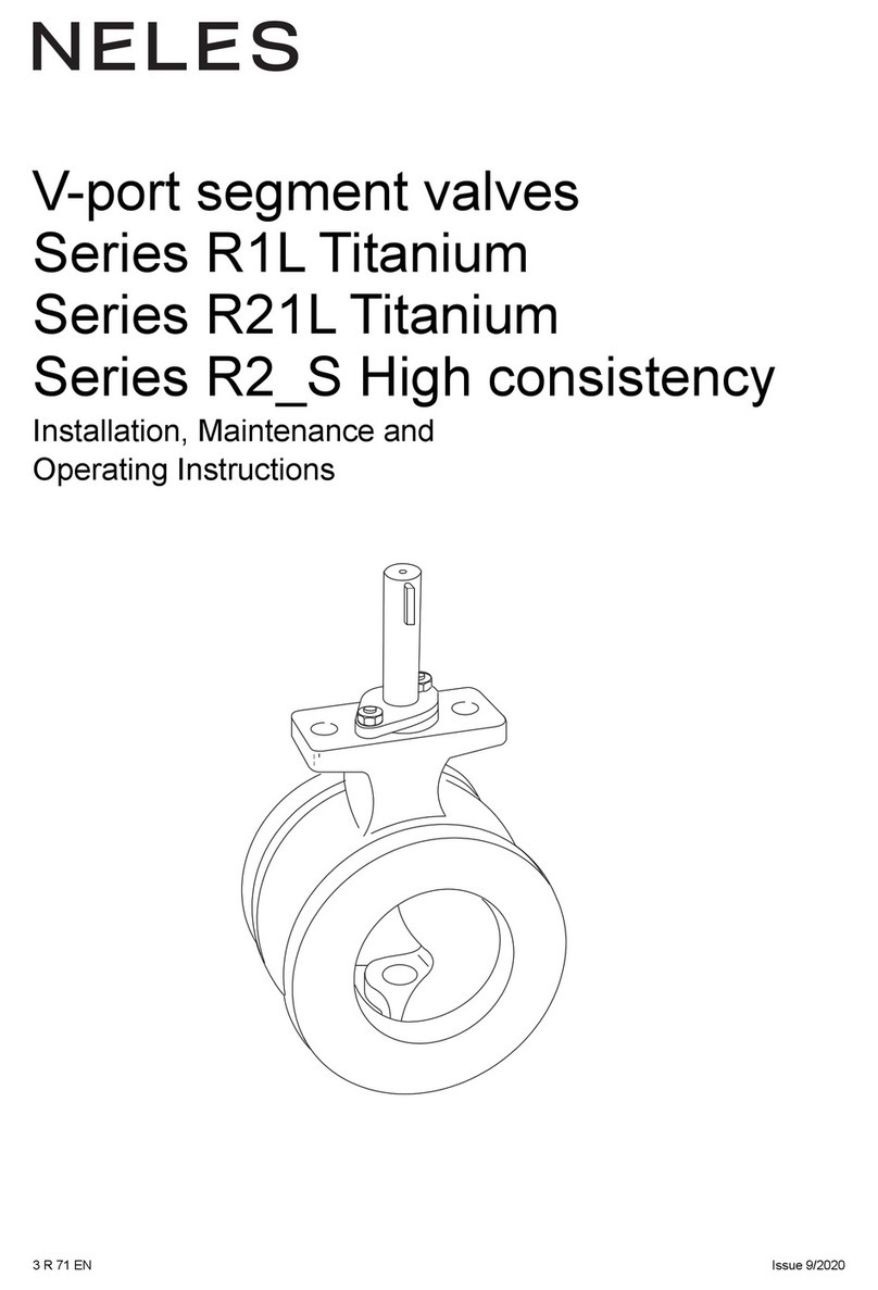
Neles R1L Titanium Series Operating and maintenance manual
Neles
Neles PB2 Series Operating and maintenance manual
Neles
Neles XG Series Operating and maintenance manual

Neles
Neles Metso T2 Series Operating and maintenance manual
Neles
Neles JAMESBURY CLINCHER 2000 Series Operating and maintenance manual
Neles
Neles Easyflow J7 Series Operating and maintenance manual
