Neptune R900 Product manual

R900®MIU Wall and Pit
Installation and Maintenance Guide


R900®MIU Wall and Pit
Installation and Maintenance Guide

Copyright
This manual is an unpublished work and contains the trade secrets and
confidential information of Neptune Technology Group Inc., which are not to be
divulged to third parties and may not be reproduced or transmitted in whole or
part, in any form or by any means, electronic or mechanical for any purpose,
without the express written permission of Neptune Technology Group Inc. All
rights to designs or inventions disclosed herein, including the right to
manufacture, are reserved to Neptune Technology Group Inc.
The information contained in this document is subject to change without notice.
Neptune reserves the right to change the product specifications at any time
without incurring any obligations.
Trademarks used in this manual R900, ARB, ProRead, and E-CODER are
registered trademarks of Neptune Technology Group Inc. Other brands or
product names are the trademarks or registered trademarks of their respective
holders.
FCC Notice
This device complies with Part 15 of the FCC Rules. Operation is subject to the
following two conditions: (1) this device may not cause harmful interference, and
(2) this device must accept any interference received, including interference that
may cause undesired operation.
NOTE: This equipment has been tested and found to comply with the limits for a
Class B digital device, pursuant to Part 15 of the FCC Rules. These limits are
designed to provide reasonable protection against harmful interference in a
residential installation. This equipment generates, uses, and can radiate radio
frequency energy and, if not installed and used in accordance with the
instructions, may cause harmful interference to radio communications.
However, there is no guarantee that interference will not occur in a particular
installation. If this equipment does cause harmful interference to radio or
television reception, which can be determined by turning the equipment off and
on, the user is encouraged to try to correct the interference by one or more of
the following measures:
lReorient or relocate the receiving antenna.
lIncrease the separation between the equipment and receiver.
lConnect the equipment into an outlet on a circuit different from that to which
the receiver is connected.
lConsult the dealer or an experienced radio / TV technician for help.

RF Exposure Information
This equipment complies with the FCC RF radiation requirements for
uncontrolled environments. To maintain compliance with these requirements,
the antenna and any radiating elements should be installed to ensure that a
minimum separation distance of 20 cm is maintained from the general
population.
Professional Installation
In accordance with section 15.203 of the FCC rules and regulations, the MIU
must be professionally installed by trained meter installers.
Changes or modifications not expressly approved by the party responsible for
compliance could void the user's authority to operate the equipment.
Industry Canada (IC) Statements
Section 8.4 of RSS-GEN
This device complies with Industry Canada License-exempt RSS standard(s).
Operation is subject to the following two conditions:
lThis device may not cause harmful interference.
lThis device must accept any interference received, including interference that
may cause undesired operation.
.Cet appareil est conforme aux normes RSS exonérées de licence d'Industrie
Canada. L'opération est soumise aux deux conditions suivantes: 1) cet appareil
ne doit pas provoquer d'interférence, et 2) cet appareil doit accepter toute
interférence, y compris les interférences pouvant entraîner un fonctionnement
indésirable de l'appareil.
Section 8.3 of RSS-GEN
Under Industry Canada regulations, this radio transmitter may only operate
using an antenna of a type and maximum (or lesser) gain approved for the
transmitter by Industry Canada. To reduce potential radio interference to other
users, the antenna type and its gain should be so chosen that the equivalent
isotropically radiated power (e.i.r.p.) is not more than that necessary for
successful communication.
This radio transmitter IC: 4171B-L900M has been approved by Industry Canada
to operate with the antenna types listed below with the maximum permissible
gain and required antenna impedance for each antenna type indicated. Antenna
types not included in this list, having a gain greater than the maximum gain
indicated for that type, are strictly prohibited for use with this device.

lMaximum permissible gain of +1 dBi and required impedance of 75 ohm.
lApproved Antenna type(s).
lR900®Pit Antenna, part number 12527-XXX
lHigh Gain R900®Pit Antenna, part number 13586-XXX
lR900®Wall Antenna, part number 13717-000
lWire monopole, part number 12641-XXX
En vertu de la réglementation d'Industrie Canada, cet émetteur radio ne peut
fonctionner qu'avec une antenne d'un type et un gain maximal (ou inférieur)
approuvé pour l'émetteur par Industrie Canada. Pour réduire les interférences
radio potentielles avec d'autres utilisateurs, le type d'antenne et son gain
devraient être choisis de manière à ce que la puissance rayonnée
isotropiquement équivalente (e.i.r.p.) ne soit pas supérieure à celle nécessaire à
une communication.
Cet Cet émetteur radio IC: 4171B-L900M a été approuvé par Industrie Canada
pour fonctionner avec les types d'antennes énumérés ci-dessous avec le gain
maximal admissible et l'impédance d'antenne requise pour chaque type
d'antenne indiqué. Les types d'antenne non inclus dans cette liste, ayant un gain
supérieur au gain maximal indiqué pour ce type, sont strictement interdits pour
être utilisés avec ce périphérique.
lGain maximal admissible de +1 dBi et impédance requise de 75 ohms.
lType.(s) d'antenne approuvé
lAntenne de puits R900®, numéro de pièce 12527-XXX
lAntenne de puits à gain élevé R900®, référence 13586-XXX
lAntenne murale R900®, numéro d'article 13717-00
lFil monopôle, numéro d'article 12641-XXX
R900®Wall and Pit MIU Installation and Maintenance Guide
Literature No. IMR900 MIU 01.19
Part No. 12560-001
Neptune Technology Group Inc.
1600 Alabama Highway 229
Tallassee, AL 36078
Tel: (800) 633-8754
Fax: (334) 283-7293
Copyright © 2006 - 2019
Neptune Technology Group Inc.
All Rights Reserved.

Contents
1
2
Chapter 1: Product Description
R900® MIU Programming
Chapter 2: Specifications 3
3
3
4
Electrical Specifications
Transmitter Specifications
Encoder Register Interface
Specifications - R900® Pit MIU 4
Environmental Conditions 4
Functional Specifications 5
Dimensions and Weight 5
Specifications - R900® Wall MIU 6
Environmental Conditions 6
Functional Specifications 6
Dimensions and Weight 7
Chapter 3: General Installation Guidelines 9
Tools and Materials 9
Safety and Preliminary Checks 10
Verifying and Preparing the Encoder Register 10
Install a Register (Non Pre-Wired or Potted Only) 11
Chapter 4: Wall Installation 15
Prior to Installation 15
Storage 15
Unpacking 15
Tools and Materials 15
Site Selection 16
Installing the R900® Wall MIU 17
Removing the Main Housing 17
Applying the Scotchlok™ Connectors 18
R900®MIU Wall and Pit Installation and Maintenance Guide vii

Activating and Completing the Installation 20
Testing the Installation 21
Chapter 5: Pit Installation 23
Prior to Installation 23
Storage 23
Unpacking 23
Tools and Materials 23
Site Selection 24
Pit MIU Installation 26
Installing the Antenna 26
Begin the Installation 28
Installing the Scotchlock™ Connectors 29
Connecting the Splice Tube 32
Tying the Cable and Activating the MIU 33
Testing the Installation 35
Chapter 6: Data Logging Extraction 37
Pairing with the Belt Clip Transceiver (BCT) 37
Accessing Data Logging 38
Initializing the Data Logger 40
Initiating RF-Activated Data Logging 42
Sample Data Logging Graph 44
Off Cycle Data Extraction 45
Chapter 7: Maintenance and Troubleshooting 47
Six-Wheel Encoder Normal Operation 47
Four-Wheel Encoder Normal Operation 47
Troubleshooting 47
Replacement Parts 48
Contact Information 48
By Phone 48
By Fax 49
viii R900®MIU Wall and Pit Installation and Maintenance Guide
Contents


This page intentionally left blank.
x R900®Wall and Pit Installation and Maintenance Guide
Contents

Figures
1
1
5
6
6
7
7
11
11
12
12
13
17
18
18
19
20
20
22
24
25
26
26
27
27
28
Figure 1 – Wall MIU
Figure 2 – Pit MIU
Figure 3 – Pit MIU Dimensions - Diagram 1
Figure 4 – Pit MIU Dimensions - Diagram 2
Figure 5 – Pit MIU Antenna
Figure 6 – Wall MIU Dimensions - Front
Figure 7 – Wall MIU Dimensions - Side
Figure 8 – Wiring a Neptune® Encoder Register
Figure 9 – MIU Color Code for Wires
Figure 10 – Cable Threaded around Strain Relief Posts
Figure 11 – Apply the Sealant
Figure 12 – Covering the Terminal Screws
Figure 13 – Wall MIU Main Housing
Figure 14 – Mounting Adapter
Figure 15 – Gel Cap Connections
Figure 16 – Cable in Back of Mounting Adapter
Figure 17 – Securing the Mounting Adapter
Figure 18 – Activating the MIU
Figure 19 – Install Seal Wire
Figure 20 – Antenna Placement for Low Traffic Areas
Figure 21 – Antenna Placement for High Traffic Areas
Figure 22 – Inserting Antenna into Pit Lid
Figure 23 – Locking Nut on Antenna
Figure 24 – Securing the Locking Nut
Figure 25 – Installation Complete
Figure 26 – MIU Housing and Latch Plate
Figure 27 – Aligning the Connector to the Housing 28
R900®MIU Wall and Pit Installation and Maintenance Guide xi

29
30
30
31
31
32
32
33
33
34
34
38
38
39
39
40
40
41
41
42
42
43
43
44
44
45
46
Figure 28 – 3M Scotchlok™ Connector
Figure 29 – MIUColor Code for Wires
Figure 30 – Seating Connector Wires
Figure 31 – Crimping Tool
Figure 32 – Improper Connections
Figure 33 – Three Color Wires Connected
Figure 34 – Splice Tube
Figure 35 – Gray Wire in Slots
Figure 36 – Cover in Place
Figure 37 – Attaching the MIU to the Antenna Shaft
Figure 38 – Activating the MIU
Figure 39 – HHU Home Screen
Figure 40 – N_SIGHT® R900® Menu Screen
Figure 41 – Data Logger Option
Figure 42 – Reader ID Input
Figure 43 – HHU Time Confirmation
Figure 44 – Initialize RF Device
Figure 45 – MIU ID Entry
Figure 46 – Capture Button
Figure 47 – Meter Size Selection
Figure 48 – Start Button
Figure 49 – Listening for Data
Figure 50 – Receiving Data
Figure 51 – Graph Button
Figure 52 – Data Logging Graph Examples
Figure 53 – HHU Home Screen
Figure 54 – HHU Menu
Figure 55 – Off Cycle Option 46
xii R900®MIU Wall and Pit Installation and Maintenance Guide
Figures

Tables
Table 1 – Transmitter Specifications 3
Table 2 – Maximum Cable Lengths 4
Table 3 – Environmental Conditions – Pit MIU 4
Table 4 – Functional Specifications – Pit MIU 5
Table 5 – Dimensions and Weight Specifications – Pit MIU 5
Table 6 – Dimensions and Weight Specifications – Wall MIU 7
Table 7 – Recommended Tools and Materials 9
Table 8 – Cable Lengths and Manufacturers for Wall Installation 16
Table 9 – Cable Lengths and Manufacturers for Pit Installation 25
Table 10 – Data Logging Graph Legend 45
Table 11 – Example Reading Values 47
Table 12 – Available Replacement Parts 48
R900®MIU Wall and Pit Installation and Maintenance Guide xiii

This page intentionally left blank.
xiv R900®MIU Wall and Pit Installation and Maintenance Guide
Tables

R900®MIU Wall and Pit Installation and Maintenance Guide 1
Chapter 1: Product Description
This chapter provides a general description of the R900®Wall and Pit Meter Interface Unit
(MIU).
The R900 MIU is a compact electronic device that collects meter reading data from an
encoder register. It then transmits the data for collection by the meter reader. The unit is
easily installed and operates within a radio frequency (RF) bandwidth which does not require
an operating license. The R900 MIU can be mounted as far as 500 feet from the encoder
register and optimum broadcast signal strength is obtainable, ensuring a high percentage of
accurate, one-pass readings.
Figure 1 – Wall MIU
Figure 2 – Pit MIU

The R900 MIU meets FCC regulations Part 15.247, allowing higher output power and greater
range. The R900 MIU uses frequency-hopping, spread-spectrum technology to avoid RF
interference and enhanced security. The MIU reads the encoder registers at 15-minute
intervals and transmits a mobile message every 14-20 seconds that includes the meter
reading data and the unique MIU ID. This allows the meter to be read by a Hand-Held Unit
(HHU) or mobile data collection unit. The MIU also transmits a high-power fixed network
message every seven and one-half minutes on an interleaved basis to an R900®Gateway. If
connected to a LoRa®network, the R900 MIU can also transmit time-synchronized hourly
readings every three hours on an interleaved basis, to a LoRa network.
The R900 MIU is designed to offer advantages to utility organizations of all sizes:
lIncreases meter reading accuracy
lEliminates hard-to-read meters
lProtects utility liability by increasing meter reader safety
R900®MIU Programming
The MIU does NOT require field programming.
2 R900®MIU Wall and Pit Installation and Maintenance Guide
Chapter 1: Product Description

R900®MIU Wall and Pit Installation and Maintenance Guide 3
Chapter 2: Specifications
This chapter contains the specifications for the R900®Meter Interface Unit (MIU).
Electrical Specifications
A lithium battery supplies the power for the MIU.
Transmitter Specifications
The following table defines the transmitter specifications for the MIU.
Specification Definition
Transmit Period lEvery 14-20 seconds – standard mobile message
lEvery seven and one-half minutes – standard, high-power, fixed
network message
lEvery three hours – standard LoRa®high-power, fixed network
message
Encoder Reading Register interrogated every 15 minutes
Transmitter Channels l50 (R900 mobile and fixed)
l64 (LoRa fixed network message)
Channel Frequency 902-928 MHz
Output Power Meets Federal Communications Commission (FCC) Part 15.247
FCC Verification Part 15.247
Table 1 – Transmitter Specifications

Encoder Register Interface
The following table defines the supported encoder maximum cable lengths.
Specification Definition
Neptune ARB®V1 300 feet (91 meters). This meets the manufacturer's
published specifications for wire length between the
encoder and the remote receptacle. The length is based on
solid three-conductor wire, 22 American Wire Gauge (AWG).
Neptune ProRead™ and
E-CODER®
500 feet (152 meters)
Sensus Protocol registers 200 feet (61 meters)
Table 2 – Maximum Cable Lengths
Specifications - R900®Pit MIU
This section defines specifications for the pit MIU.
Environmental Conditions
The following table defines the environmental conditions for the pit MIU.
Condition Definition
Operating Temperature –22° to 149°F (–30° to 65°C)
Storage Temperature –40° to 158°F (–40° to 70°C)
Operating Humidity 0 to 100% condensing
Table 3 – Environmental Conditions – Pit MIU
4 R900®MIU Wall and Pit Installation and Maintenance Guide
Chapter 2: Specifications

Functional Specifications
The following table defines the functional specifications for the pit MIU.
Specification Definition
Register Reading Eight digits
MIU ID 9 or 10 digits
Table 4 – Functional Specifications – Pit MIU
Dimensions and Weight
The following table defines the dimensions and weight for the pit MIU.
Specification Definition
Dimensions
See "Pit MIU Dimensions - Diagram 1" below, "Pit MIU
Dimensions - Diagram 2" on the next page, and "Pit MIU
Antenna" on the next page
Weight 1.0 lbs. (454 grams)
Table 5 – Dimensions and Weight Specifications – Pit MIU
Figure 3 – Pit MIU Dimensions - Diagram 1
R900®MIU Wall and Pit Installation and Maintenance Guide 5
Chapter 2: Specifications
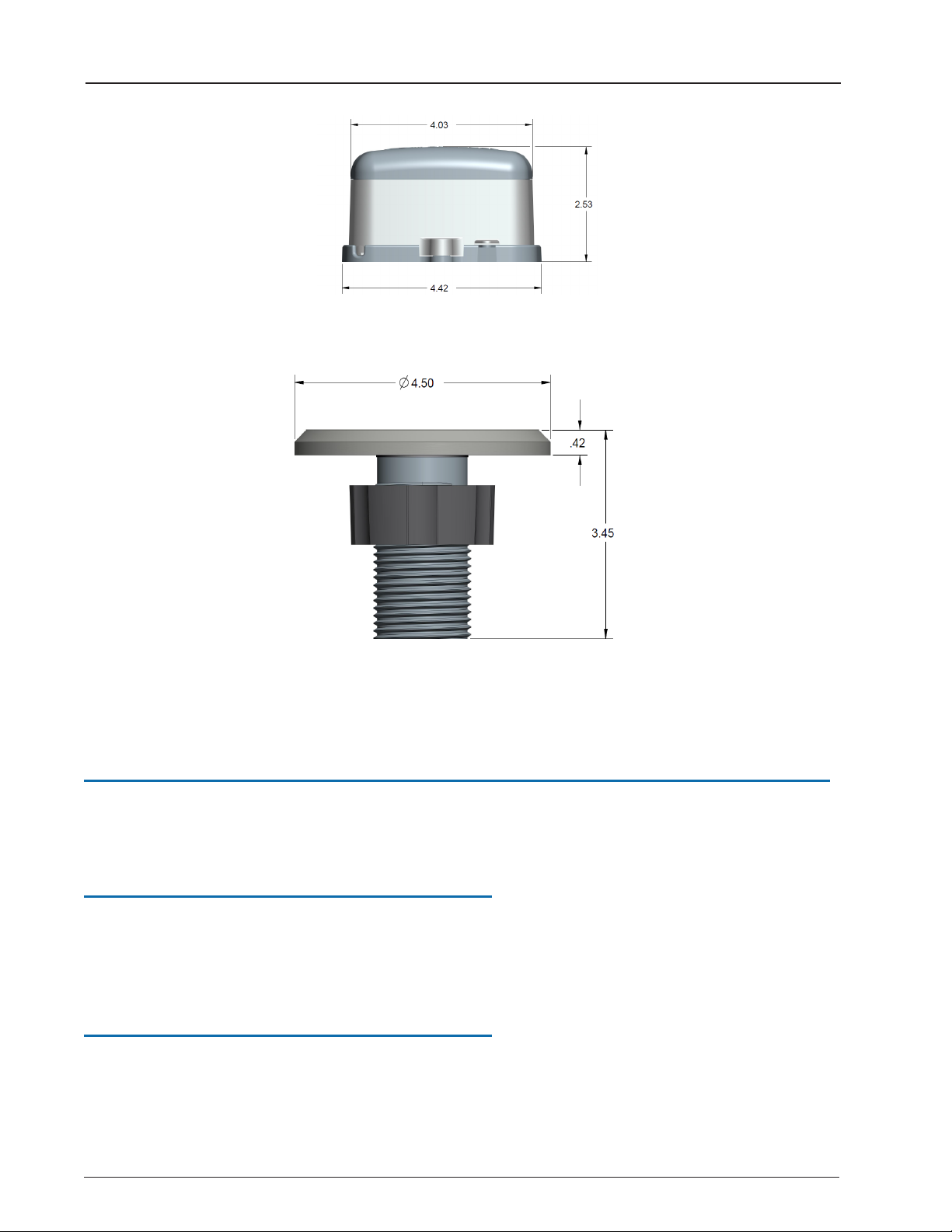
Figure 4 – Pit MIU Dimensions - Diagram 2
Figure 5 – Pit MIU Antenna
Specifications - R900®Wall MIU
This section defines specifications for the wall MIU.
Environmental Conditions
The environmental conditions for the wall MIU are the same as for the pit MIU. See
"Environmental Conditions" on page4.
Functional Specifications
The functional conditions for the wall MIU are the same as for the pit MIU. See
"Specifications" on page3.
6 R900®MIU Wall and Pit Installation and Maintenance Guide
Chapter 2: Specifications
Other manuals for R900
5
Table of contents
Other Neptune Data Logger manuals


