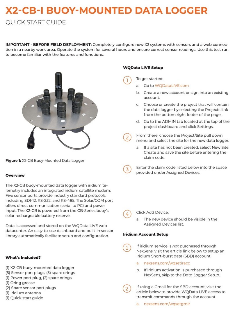
NexSens Technology X2-CB User manual

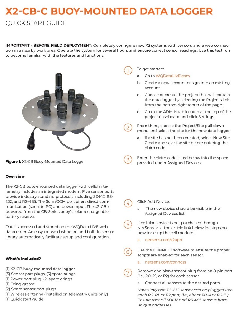
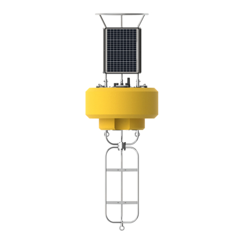
X2-CB Buoy-Mounted Data Logger
User Guide
Last Revision: 26 September 2022
Date Generated: 28 September 2022
Copyright © 2022 NexSens Technology, Inc.

Table of Contents
1. System Power
Apply Power to the X2-CB
Power Jumper
Basic Requirements
Connector Wiring
Power & Communications Accessories
UW-6 Universal Pinout
Buzzer Indicator
Performing a Measurement System Power Budget
Instructions for Use
Advanced Custom User Entry
Disclaimer
2. Establish Communication
X2 Data Flow
Wi-Fi
Cellular
Iridium
Radio to Cellular
Radio to PC
Cellular
Set up a 4G Cellular Account for an X2 Data Logger
Install a SIM Card into an X2-CB/X2-CBMC Cellular Logger
Set an APN on an X2 Data Logger Using CONNECT
Iridium
Setup Gmail Account to Allow WQData LIVE Access (Iridium)
Setup Iridium (SBD) Data Account
Setup Iridium Logger Through CONNECT
Iridium Transmission Delay
Radio
Set Up a NexSens Radio Network
3. Connect Sensors
X2 Supported Sensors
Tier 1 Sensors
Tier 2 Sensors
Tier 3 Sensors
CONNECT Software
UW Connectors
UW-8 Sensor Port Pinout
4
4
4
5
5
6
7
9
10
10
15
15
16
16
16
17
18
19
20
21
21
22
29
37
37
41
44
47
49
49
56
56
56
58
59
60
61
61
2

UW-8 Plug Pinout
X2 Sensor Detection
When Sensor Detections Occur
Important Considerations
Setup in WQData LIVE
Creating a Project on WQData LIVE
Adding a Data Logger to a Project on WQData LIVE
Changing Sensor Logging Intervals
Changing Data Logger Transmission Interval
Run Remote Sensor Detection
X2 Logger Diagnostic Readings
X2 Meta Parameter Descriptions
4. Troubleshooting and Maintenance
Sensor(s) Not Found During X2 Auto-Detection
Verify Battery Voltage of a CB-Series Buoy
Replace a Battery in a CB-Series Data Buoy
Battery Removal
New Battery Installation
Remove an X2/iSIC-CB for repair
Replace Desiccant
Check an Antenna Connection on an X2-CB
Component Overview
Verify a Connection is Tight
Inspect the RF Connectors for Moisture
Access a SD Card
Remove the X2-CB Housing
Access RTU SD Card
Access Main SD Card
Reassemble the X2-CB Housing
X2 Storage Requirements
5. Warranty
62
63
63
63
64
64
66
69
70
71
73
73
77
77
78
79
79
81
85
88
92
92
92
93
100
100
103
105
109
114
115
3

1. System Power
Apply Power to the X2-CB
The X2-CB has an innovative power design that allows for simple connectivity and interfacing with sensors on
NexSens CB-Series buoys.
Power Jumper
CB-Series solar towers have a special UW-6 plug with a jumper built in that completes the circuit for the battery
to supply power to the X2-CB data logger. The X2-CB will not receive power unless the solar panel is
connected to the COM/SOLAR port. Alternatively, a UW-JUMPER plug may be connected to the COM/SOLAR
port to complete the connection.
NexSens CB-Series Jumper Plug
X2-CB Buoy-Mounted Data Logger.
CB-Series jumper plug.
4

Basic Requirements
Supply Voltage: 5-24VDC [+/-15%]
Operating Current Max: 300mA
Peak Current: 500mA for 1 second (@ 12V)
All standard CB-Series buoys meet and exceed the X2-CB required specifications.
Connector Wiring
Solar power is supplied to the CB-Series battery pack via the UW-6 Receptacle (marked ‘COM/SOLAR‘) port,
which also acts as a power switch between the battery and data logger. This allows quick power disconnection
when the logger is not in use, as removing the solar plug from the port also removes power from the logger. The
below table and diagram show the proper connections for the X2-CB’s UW-6R port.
X2-CB UW6 Power Port Pinout
Pin Number X2 Wire Color Signal
1 Green Host RS-485A
2 Blue Host RS-485B
3 Red BAT +
4 Black X2 GND | Regulator GND | BAT –
5 Yellow Regulator Solar
6 Orange X2 Primary Power | Regulator BAT
NexSens UW-6 receptacle port pin numbering.
5

The schematic below shows the CB-Series buoy wiring from top to bottom.
Power & Communications Accessories
Please visit the accessories tab on the X2-CB product page to purchase power/comms accessories.
CB-PW-AC-30W: CB-Series battery float charger, 30W
CB-PW-AC-60W: CB-Series battery float charger, 60W
UW6-USB-485P: Direct connect USB PC cable
X2-CB power schematic.
6

UW-6 Universal Pinout
The schematics and table below details the 6-pin plug and receptacle universal pinout for all 6-pin NexSens
cables excluding the 6-pin AC adapter.
Figure 1: NexSens UW-6 receptacle pinout Figure 2: NexSens UW-6 plug pinout
Figure 3: X2-CBMC/SDLMC MCIL-6-FS 6-pin power
port Figure 4: NexSens MCIL-6 plug pinout
7

Universal Pinout
Note: For instruments shown below, all signals in the table refer to their 6-pin receptacle port.
Plug Pin Receptacle Pin Wire Color G2-Series Signal X2 Signal X2-CB Buoy Solar Signal**
1 6 Red Ext. Power Input Main Power Input X2 PCB Power In
2 5 Yellow — Secondary Pwr Input* Unregulated Solar In
3 4 Black Ground Ground Ground
4 3 White — Backup Power Input Internal Buoy Bat.
5 2 Blue RS-485 B RS-485 B RS-485 B
6 1 Green RS-485 A RS-485 A RS-485 A
*X2-SDL’s purchased after
August 2021 do not include
secondary power.
**Wire colors for the X2-
CB/X2-CBMC follow the UW-6
Bulk Pinout
iSIC-V2 X2 X2-CB**
G2-RAIN X2-SDL* X2-CBMC**
G2-EXO X2-SDLMC
8

Buzzer Indicator
X2-SDL & X2-CB data loggers are equipped with an onboard buzzer to provide audible system status feedback
to the user.
X2-SDL/X2-CB Buzzer Indicator Status Lookup
Event Beep Type Status
When power is applied Short beep System boot successful
During telemetry connection Two short beeps Connection successfully established
During telemetry connection Three short beeps No signal/connection failed
During Sensor Detection 3 second beep WQData LIVE setup completed
successfully
9

Performing a Measurement System Power Budget
Analyzing a measurement system power budget is a useful practice to help ensure that a proposed system
design will meet the monitoring objectives and reliably deliver data. To aid with this, NexSens has developed a
power budget tool which can quickly estimate the expected power performance of systems using the most
common NexSens buoy platforms, data logger configurations, and commonly integrated NexSens and third-party
sensors for deployment locations throughout the world.
The power budget tool is frequently updated with site locations, sensor types and other information. Contact a
NexSens applications engineer to request an up-to-date copy:
Contact NexSens
Instructions for Use
1. Begin by entering the company and/or project name and date in the top section. It is recommended to save
the file with a unique identifier before proceeding past this point.
2. Proceed to enter basic information about the system – equipment type (logger and hardware), telemetry
option (if any), sample and transmit intervals, and extra battery if used.
a. The example below shows a CB-950 data buoy with X2 data logger and CB-A05-3 battery pack with (3)
28 A-hr batteries. The system will sample every 20 minutes and transmit all data every 60 minutes and
has no additional batteries connected (as is normal on buoy-based systems).
3. Proceed to select the sensors to be connected to the system from the predefined sensor list (drop-down
menu in Sensor column). Select the quantity of each sensor type and whether they will use full power,
switch power or internal power.
a. The example below shows an Airmar 200WX-IPX7 weather station, NexSens T-Node FR temperature
string with 10 nodes, Nortek Signature 1000 current profiler, and a YSI EXO3 sonde all on switch
power.
Project information header.
Enter system information.
10

Select sensors from drop-down list.
11

b. While the pre-populated sensor list is fairly extensive and frequently updated, there may be cases
where a sensor is not listed. In such cases, it is possible to enter up to four devices manually by
selecting Custom 1/2/3/4 from the drop-down list.
Custom sensor entry.
12

c. Once selected, proceed to the Custom User Entry tab of the spreadsheet. Navigate to the Sensor
Details section and fill in the prompted information either using data from the device manufacturer or
measured data during device testing.
Custom sensor data entry.
13

d. Note that some instrument types have a number of different configurations which may affect power
performance. The predefined sensors in the drop-down list are set up based on a typical configuration
and information provided by the manufacturer or NexSens bench testing where applicable. These
therefore represent a best approximation based on available information. However, these may also be
edited manually in the Sensor Details section of the Power Budget Calculation tab if more precise
information is available.
4. Once all sensor information is entered, select a deployment location from the drop-down list. The predefined
list contains locations throughout the world, and it is normally sufficient to select the closest possible
location provided that the latitude and general climate conditions are similar. However, if an appropriate
location does not appear to be available, it is recommended to contact NexSens as new locations can
normally be added quickly upon request.
5. Select which months of the year the system is expected to be deployed. In many cases, all months will be
selected, and December will be the limiting month for sites in the northern hemisphere. However, this option
is given because, particularly for data buoy systems, some applications require only seasonal or short-term
deployment.
6. Having entered all equipment information and deployment site conditions, the Results section will now
display the calculated results.
Select deployment location.
Select months of active deployment.
Calculated results display.
14

a. Reserve Days refers to how long the system could operate if starting with near 100% battery charge
during an extended period without solar charging, or how long a system without any solar charging can
be expected to operate. For solar-charged systems, a rule of thumb is to target at least two weeks (14
days) of reserve power.
b. Panels Available refers to how many individual panels are available in a solar array. CB-Series buoys
normally have three panels on the solar tower. Since these are oriented such that all three cannot
receive sunlight simultaneously, this is accounted for in the power budget by efficiency factors built into
the calculation. It is therefore not necessary to change this value.
c. Panels Required refers to the calculated result for solar charge capacity needed to support the given
configuration. It must be less than the Panels Available in order for the system to support the
application as defined.
d. Sufficient Power provides a yes/no answer for whether the selected hardware, logging and transmit
configuration is supportable. If it is not, it displays how many additional panels would theoretically be
required. Adjustments can be made to the system design until a viable result is achieved.
Advanced Custom User Entry
Because flexibility for use with user-supplied loggers, batteries, sensors and other electronics is a basic design
principle of NexSens CB-Series data buoys, the power budget calculator also facilitates user entry of data for all
components.
Besides just the Custom sensor data entry noted in step 3 above, the Custom User Entry tab supports input of
user-supplied data loggers, solar panels, telemetry systems and battery packs, as well as solar insolation for the
exact deployment location.
These fields can be activated by selecting the Custom entry option for equipment type, telemetry type, extra
battery, sensors, and/or deployment location as illustrated below.
Disclaimer
The NexSens power budget calculator is intended as a helping tool for correct system design. It integrates
efficiency factors and other conservative estimates of power consumption in order to provide a best possible
approximation of system power performance and viability. However, real-world conditions may vary, and field
testing is the only way to ensure that a system will perform adequately. NexSens does not assume liability for
any system that does not perform in accordance with power budget estimates.
Custom user entry options.
15

2. Establish Communication
X2 Data Flow
The X2 is designed to provide real-time data to users. The diagrams below outline how the data travels from
sensor to user.
Wi-Fi
X2 to WQData LIVE.
16

Cellular
X2-C to WQData LIVE.
17

Iridium
X2-I to WQData LIVE.
18

Radio to Cellular
X2-RC to WQData LIVE.
19

Radio to PC
Notes:
Data is posted to WQData LIVE’s secure MySQL database using HTTP POST protocol
Data is transmitted in XML format
X2-R to WQData LIVE.
20
Table of contents
Other NexSens Technology Data Logger manuals

NexSens Technology
NexSens Technology CB-40 User manual

NexSens Technology
NexSens Technology CB-25 User manual

NexSens Technology
NexSens Technology CB-50 User manual

NexSens Technology
NexSens Technology X2-CB-C User manual

NexSens Technology
NexSens Technology CB-150 User manual

NexSens Technology
NexSens Technology CB-250 User manual

NexSens Technology
NexSens Technology CB-950 User manual

NexSens Technology
NexSens Technology X2 User manual

NexSens Technology
NexSens Technology X2-CB-I User manual

NexSens Technology
NexSens Technology iSIC-OEM User manual