netvox R718UBD Series User manual

Wireless Multifunctional CO2 Sensor
R718UBD Series
Wireless Multifunctional
CO2 Sensor
R718UBD Series
User Manual
Copyright©Netvox Technology Co., Ltd.
This document contains proprietary technical information which is the property of NETVOX Technology. It shall be
maintained in strict confidence and shall not be disclosed to other parties, in whole or in part, without written
permission of NETVOX Technology. The specifications are subject to change without prior notice.

1
Table of Content
1. Introduction..........................................................................................................................................2
2. Appearance...........................................................................................................................................4
3. Main Feature.........................................................................................................................................4
4. Set up Instruction..................................................................................................................................5
5. Data Report ..........................................................................................................................................6
5.1 Example of ReportDataCmd..........................................................................................................7
5.2 Example of ConfigureCmd............................................................................................................8
5.3 Example of calibration configuration...........................................................................................10
6. Installation..........................................................................................................................................12
6-1 Precautions for use of dust sensor................................................................................................12
6-2. Precautions for use of TVOC sensor...........................................................................................12
6-3 Precautions for outdoor installation.............................................................................................13
7. Important Maintenance Instruction.....................................................................................................14

2
1. Introduction
R718UBD all-in-one series is a ClassA type of netvox based on LoRaWAN open protocol, which can support a variety of combined
detection devices composed of temperature and humidity, CO2, vibration, atmospheric pressure, illumination, TVOC and dust, and is
compatible with LoRaWAN protocol.
LoRa Wireless Technology:
LoRa is a wireless communication technology dedicated to long distance and low power consumption. Compared with other
communication methods, LoRa spread spectrum modulation method greatly increases to expand the communication distance. Widely
used in long-distance, low-data wireless communications. For example, automatic meter reading, building automation device,
wireless security systems, industrial monitoring. Main features include small size, low power consumption, transmission distance,
anti-interference ability and so on.
LoRaWAN:
LoRaWAN uses LoRa technology to define end-to-end standard specifications to ensure interoperability between devices and
gateways from different manufacturers.

3
The specific model of R718UBD all-in-one is shown in the following table:
UBD represents the basic function CO2 of DC power supply
“1” represents temperature and humidity,
“2” represents vibration
“3” represents air pressure
“5” represents light
“6” represents TVOC
“7” represents PM2.5
Device Model Product functions
R718UBD CO2
R718UBD1 CO2, temperature and humidity
R718UBD12 CO2, temperature and humidity, vibration
R718UBD123 CO2, temperature and humidity, vibration, air pressure
R718UBD23 CO2, vibration, air pressure
R718UBD25 CO2, vibration, light
R718UBD125 CO2, temperature and humidity, vibration, light
R718UBD235 CO2, vibration, air pressure, light
R718UBD1235 CO2, temperature and humidity, vibration, air pressure, light
R718UBD126 CO2, temperature and humidity, vibration, TVOC
R718UBD1236 CO2, temperature and humidity, vibration, air pressure, TVOC
R718UBD127 CO2, temperature and humidity, vibration, PM2.5
R718UBD1237 CO2, temperature and humidity, vibration, air pressure, PM2.5
R718UBD12357 CO2, temperature and humidity, vibration, air pressure, light, PM2.5
R718UBD1257 CO2, temperature and humidity, vibration, light, PM2.5/10
R718UBD256 CO2, vibration, light, TVOC
R718UBD257 CO2, vibration, light, PM2.5/10
R718UBD236 CO2, vibration, air pressure, TVOC
R718UBD237 CO2, vibration, air pressure, PM2.5/10
R718UBD2356 CO2, vibration, air pressure, light, TVOC
R718UBD2357 CO2, vibration, air pressure, light, PM2.5/10
4
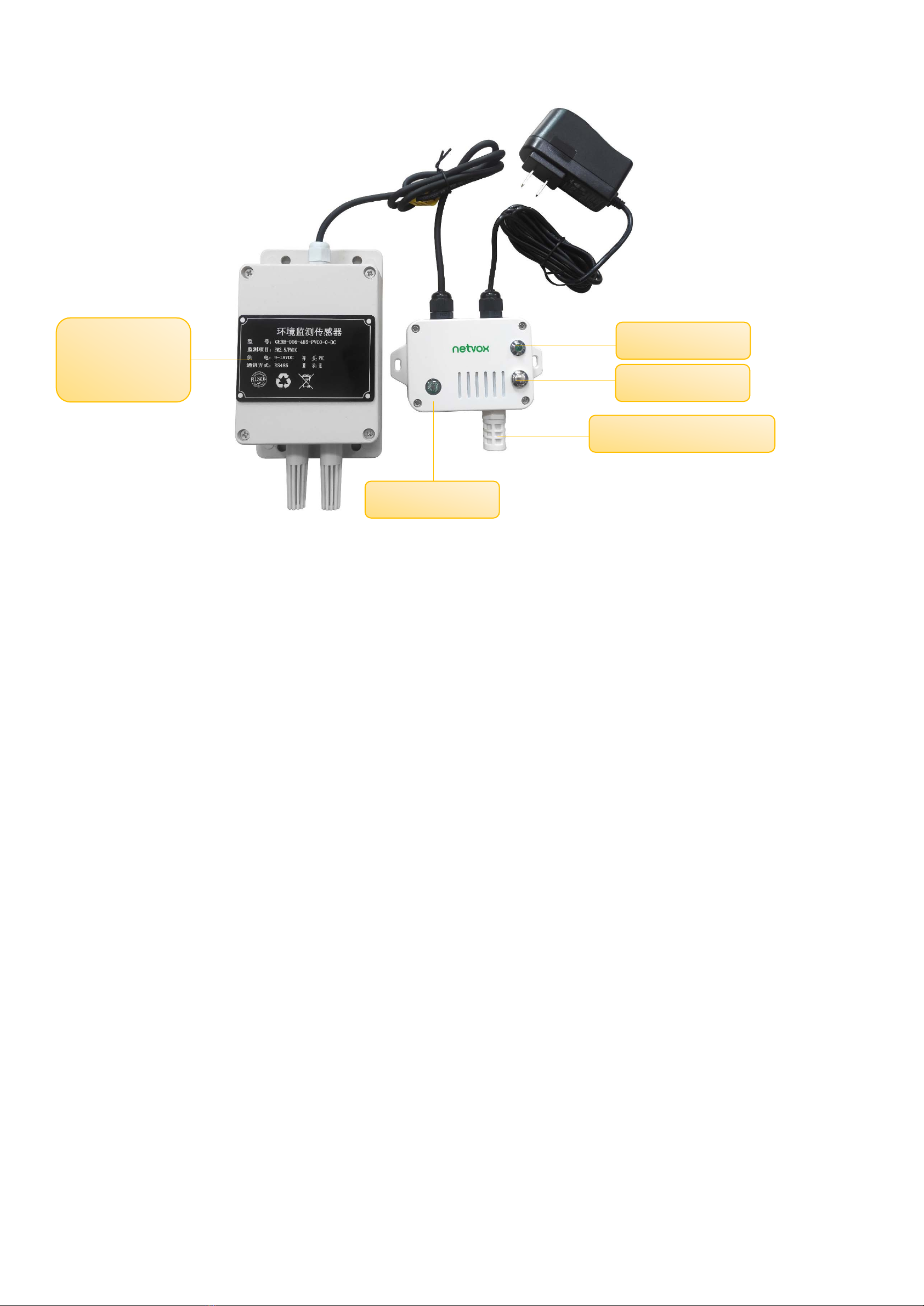
2. Appearance
3. Main Feature
Apply SX1276 wireless communication module
DC 12V power supply
It can detect temperature and humidity, CO2, vibration, atmospheric pressure, illumination, TVOC and dust
The base is attached with a magnet, which can be adsorbed on iron objects
Host Body Protection Level: IP65
Compatible with LoRaWANTM Class A
Frequency Hopping Spread Spectrum (FHSS) technology
Configuration parameters can be configured through third-party software platforms, data can be read and alarms can be set via
SMS text and email (optional)
Available third-party platform: Actility / ThingPark, TTN, MyDevices/Cayenne
Indicator
Temperature and humidity
Function Key
Dust sensor
(PM2.5 / PM10)
Light Sensor

5
4. Set up Instruction
On/Off
Power on Power on
Restore to factory setting Press and hold the function key for 5 seconds till green indicator flashes 20 times.
Power off Remove adapter
Note:
1. On/off interval is suggested to be about 10 seconds to avoid the interference of capacitor
inductance and other energy storage components.
2. In the first 5 seconds after power on, the device will be in engineering test mode.
Network Joining
Never joined the network
Turn on the device to search the network to join.
The green indicator stays on for 5 seconds: success
The green indicator remains off: fail
Had joined the network
(not at factory setting)
Turn on the device to search the previous network to join.
The green indicator stays on for 5 seconds: success
The green indicator remains off: fail
Fail to Join The Network Suggest to check the device verification information on the gateway or consult your platform
server provider.
Function Key
Press and hold for 5 seconds
Restore to factory setting
The green indicator rapidly flashes for 20 times: success
The green indicator remains off: fail
Press once The device is in the network: green indicator flashes once and sends a report
The device is not in the network: green indicator remains off
Sleeping Mode
The device is on and in the network
Sleeping period: Max Interval.
When the reportchange exceeds setting value or the state changes: send a data report according
to Max Interval.

6
5. Data Report
When the device is powered on, it will immediately send a version package report and then report the device data.
Default setting:
Min interval = 10s // The interval between multiple data packets
Max interval = 900s
Report count=1, R718UBD, R718UBD1, R718UBD12
Report count=2, R718UBD123, R718UBD23, R718UBD25, R718UBD125, R718UBD235, R718UBD 1235
R718UBD126, R718UBD127
Report count=3, R718UBD1236, R718UBD1237, R718UBD12357, R718UBD1257, R718UBD256, R718UBD257,
R718UBD236, R718UBD237
Data detection:
When the device is in a network state, the light flashes once after pressing the key, and then reads the data. When the time to
return the corresponding data or configure is up, it will also detect and return the corresponding data information.
(Note: The interval between multiple data packets is mintime)
Note:
1. Before any configuration, the device sends data according to the default configuration.
2. Do not send any configuration before turn on the device.
3. CO2 data will be unstable due to transportation relations, long storage time and other factors.
If the CO2 value which customers test is inconsistent ,or there is large discrepancy of the primary standard,
it can be recalibrated. For specific calibration methods,please refer to command 0x03 CalibrateType.
Refer to Netvox LoRaWan Application Command documents and for data analysis reported by the device
http://www.netvox.com.cn:8888/page/index Instruction parsing
The report configuration and sending time are as follows:
Min Interval (Unit: s) Max Interval (Unit: s) Sending interval of multiple data packets Report cycle
Not 0 Mintime * reportcount ~ 65535 By Min Time Report Report by Max Time

7
5.1 Example of ReportDataCmd
FPort:0x06
Bytes 1 1 1 Var(Fix=8 Bytes)
Version DeviceType ReportType NetvoxPayLoadData
Version– 1 byte –0x01——the Version of NetvoxLoRaWAN Application Command Version
DeviceType– 1 byte – Device Type of Device
The devicetype is listed in Netvox LoRaWAN Application Devicetype doc
ReportType – 1 byte –the presentation of the NetvoxPayLoadData,according the devicetype
NetvoxPayLoadData– Fixed bytes (Fixed =8bytes)
Device Device
type
Report
type NetvoxPayloadData
R718UBD 0xBB
0x01
Battery
(1Byte)
unit:0.1V)
Temperature
(Signed 2Bytes)
unit:0.01°C
Humidity
(2Bytes)
unit:0.01%
CO2
(2Bytes)
unit:1ppm
ShockEvent
(1Byte)
0x00_NoShock
0x01_ Shock
0x02 Battery
(1Byte, unit:0.1V)
AirPressure
(4Bytes,unit:0.01hPa)
illuminance
(3Bytes,unit:1Lux)
0x03
Battery
(1Byte)
unit:0.1V
PM2.5
(2Bytes)
Unit:1 ug/m3
PM10
(2Bytes)
Unit: 1ug/m3
TVOC
(2Bytes)
Unit:1ppb
Reserved
(1Byte)
fixed 0x00
R718UBD12357 report example:
# Report data 1: 01BB0100097A151F020C01
1st byte (01): Version
2nd byte (BB): DeviceType 0xBB -R718UBD Series
3rd byte (01): ReportType
4th byte (00): Battery-0x00 means is powered by DC power source
5th 6th byte (097A): Temperature-24.6°C ,097A(HEX)=2426(DEC),2426*0.01°C =24.26°C
7th 8th byte (151F): Humidity-54.07% , 151F(HEX)=5407(DEC),5407*0.01%=54.07%
9th 10th byte (020C): CO2-524ppm , 020C(HEX)=524(DEC),524*1ppm=524ppm
11th byte (01): Shock Event-1 , Shock
# Report data 2: 01BB02000001870F000032
1st byte (01): Version
2nd byte (BB): DeviceType 0xBB -R718UBD Series

8
3rd byte (02): ReportType
4th byte (00): Battery-0x00 means is powered by DC power source
5th ~ 8th byte (0001870F): AirPressure-1001.11hPa,1870F(HEX)=100111(DEC),100111*0.01hPa=1001.11hPa
9th ~11th byte (000032): Illuminance-50 Lux ,000032(HEX)=50(DEC),50*1Lux=50Lux
# Report data 3: 01BB030000110011FFFF00
1st byte (01): Version
2nd byte (BB): DeviceType 0xBB -R718UBD Series
3rd byte (03): ReportType
4th byte (00): Battery-0x00 means is powered by DC power source
5th 6th byte (0011):PM2.5-17ug/m3, 11(HEX)=17(DEC)
7th 8th byte (0011): PM10-17ug/m3, 11(HEX)=17(DEC)
9th 10th byte (FFFF): TVOC
11th byte (00): Reserved
Note:
Unsupported sensor detection item data is 0xFF/0xFFFF/0xFFFFFF/0xFFFFFFFF
5.2 Example of ConfigureCmd
FPort:0x07
Bytes 1 1 Var (Fix =9 Bytes)
CmdID DeviceType NetvoxPayLoadData
CmdID– 1 byte
DeviceType– 1 byte – Device Type of Device
NetvoxPayLoadData– var bytes (Max=9bytes)
Description Device CMD
ID
Report
type NetvoxPayloadData
Config
ReportReq
R718UBD
0x01
0xBB
MinTime
(2bytes Unit:s)
MaxTime
(2bytes Unit:s)
Reserved
(2Bytes,Fixed 0x00)
Config
ReportRsp 0x81 Status
(0x00_suBBess)
Reserved
(8Bytes,Fixed 0x00)
ReadConfig
ReportReq 0x02 Reserved
(9Bytes,Fixed 0x00)
ReadConfig
ReportRsp 0x82 MinTime
(2bytes Unit:s)
MaxTime
(2bytes Unit:s)
Reserved
(2Bytes,Fixed 0x00)

9
Calibrate
CO2Req 0x03
CalibrateType (1Byte)
0x01_TargetCalibrate
0x02_ZeroCalibrate
0x03_BackgroudCalibrate
0x04_ABCCalibrate
CalibratePoint
(2Bytes,Unit:1ppm)
Only valid in
targetCalibrateType
Reserved
(6Bytes,Fixed 0x00)
Calibrate
CO2Rsp 0x83 Status
(0x00_suBBess)
Reserved
(8Bytes,Fixed 0x00)
SetShockSensor
SensitivityReq 0x04 ShockSensorSensitivity
(1Byte)
Reserved
(8Bytes,Fixed 0x00)
SetShockSensor
SensitivityRsp 0x84 Status
(0x00_success)
Reserved
(8Bytes,Fixed 0x00)
GetShockSensor
SensitivityReq 0x05 Reserved
(9Bytes,Fixed 0x00)
GetShockSensor
SensitivityRsp 0x85 ShockSensorSensitivity
(1Byte )
Reserved
(8Bytes,Fixed 0x00)
(1)Configure the device parameter MinTime = 300s, MaxTime = 900s
Downlink: 01BB012C03840000000000//12C(Hex)=300(Dec), 384(Hex)=900(Dec)
Device return:
81BB000000000000000000 (configuration successful)
81BB010000000000000000 (configuration failed)
(2) Read the device parameter
Downlink: 02BB000000000000000000
Device Return:
82BB012C03840000000000 (device current parameter)
(3) Set CO2 calibration
Downlink:
03BB0103E8000000000000 // Select Target-calibrations
(calibrate when the known CO2 concentration is 1000ppm (concentration optional))
03BB020000000000000000 // Select Zero-calibrations
(Calibration in an environment with a CO2 concentration of 0 ppm)
03BB030000000000000000 // Select Background calibrations
(calibration shall be carried out in a stable environment in fresh air, i.e. 400 ppm concentration)
03BB040000000000000000 // Select ABC calibrations

10
(self calibration is default when power on, and 8 days is a cycle of self calibration. The sensor must be exposed to
fresh air at least once (well ventilated) for calibration)
Device return:
83BB000000000000000000 (configuration successful)
// Successfully configured, (Target/Zero/Background/ABC-alignments)
83BB010000000000000000 (configuration failed)
//After calibration, the returned CO2 value is not within the error range
(4) SetShockSensorSensitivityReq:
The effective range of the configuration is 0x01~0x14, and the vibration function is turned off when it is set to 0xFF
Downlink: 04BB0A0000000000000000 //Set ShockSensorSensitivity = 10 (Dec)
Device return:
84BB000000000000000000 (device current parameter)
(5) GetShockSensorSensitivityReq:
Downlink: 05BB000000000000000000
Device return:
85BB0A0000000000000000 (device current parameter)
5.3 Example of calibration configuration
FPort:0x0E
Description Cmd
ID
Sensor
Type PayLoad(Fix =9 Bytes)
SetGlobal
CalibrateReq 0x01
See
below
Channel (1Byte)
0_Channel1
1_Channel2,etc
Multiplier
(2bytes,Unsigned)
Divisor
(2bytes,Unsigned)
DeltValue
(2bytes,Signed)
Reserved
(2Bytes,Fixed 0x00)
SetGlobal
CalibrateRsp 0x81
Channel (1Byte)
0_Channel1
1_Channel2,etc
Status
(1Byte,0x00_success)
Reserved
(7Bytes,Fixed 0x00)
GetGlobal
CalibrateReq 0x02
Channel (1Byte)
0_Channel1
1_Channel2,etc
Reserved
(8Bytes,Fixed 0x00)
GetGlobal
CalibrateRsp 0x82
Channel (1Byte)
0_Channel1
1_Channel2,etc
Multiplier
(2bytes,Unsigned)
Divisor
(2bytes,Unsigned)
DeltValue
(2bytes,Signed)
Reserved
(2Bytes,Fixed 0x00)
ClearGlobal 0x03 Reserved 10Bytes,Fixed 0x00)

11
CalibrateReq
ClearGlobal
CalibrateRsp 0x83 Status
(1Byte,0x00_success)
Reserved
(9Bytes,Fixed 0x00)
The calibrationsensor type and channel corresponding to each sensor :
Sensor Sensor Type Channel
Temperature 0x01 0x03
Humidity 0x02 0x04
Light 0x03 0x05
PM2.5 0x04 0x01
PM10 0x02
CO2 0x06 0x00
Air Press 0x35 0x06
TVOC 0x40 0x07
(1)Assume that the reported original value of CO2 is 500ppm, the calibration increases by 100ppm, and the reported value is
600ppm.
SetGlobalCalibrateReq: Calibration increased by 100ppm,Multiplier =0x0001,Divisor = 0x0001,DeltValue = 0x0064
Downlink: 0106000001000100640000
Device return:8106000000000000000000 (configuration successful)
8106000100000000000000 (configuration failed)
(2)GetGlobalCalibrateReq:
Downlink:0206000000000000000000
Device return:8206000001000100640000
(3)Assume that the reported original CO2 value is 500ppm, the calibration is reduced by 100ppm, and the reported value is 400ppm
SetGlobalCalibrateReq: Calibration reduction by 100ppm,Multiplier =0x0001,Divisor = 0x0001,DeltValue = 0xFF9C
Downlink: 01060000010001FF9C0000
Device return:8106000000000000000000
(4) GetGlobalCalibrateReq:
Downlink:0206000000000000000000
Device return:82060000010001FF9C0000
(5)ClearGlobalCalibrateReq (Clear calibration value: reported value returns to 500ppm)
Downlink: 0300000000000000000000
Device return:8300000000000000000000

12
6. Installation
The waterproof breathable film inside the product is waterproof but not waterproof against steam. Therefore, in order to prevent water
vapor from condensing inside the body, it should not be used in high humidity and steam environments.
6-1 Precautions for use of dust sensor
The sensor is made of water-resistant, dust-proof, and impact resistant materials. However, precision instruments need to be
carefully used and maintained to avoid impact and use in harsh environments such as corrosive liquids or gases.
The air inlet of the sensor shall not be blocked or polluted.
The electrolyte leakage will cause damage. Do not disassemble the sensor at will.
Do not use it when the shell is damaged or deformed.
The sensor shall avoid contact with organic solvents (including silicone rubber and other adhesives), coatings, agents, and fuel oils.
It is not recommended to use non-standard methods to test the sensor, and vertical air intake must be avoided. For example, put
the sensor directly on the concentrated ammonia, spray cigarettes towards the sensor, approach the sensor after the lighter is lit,
exhale towards the sensor, and close the sensor to alcohol. Because the regional concentration can be as high as tens of thousands
of ppm when liquid ammonia or alcohol volatilizes, and the carbon dioxide concentration in human breath can be as high as 40000
ppm, which will damage the sensor.
After being used for a long time in a high-concentration gas environment (it is prohibited to store and use it in a high-concentration
acid gas for a long time), it is slow to recover to the initial state.
When the sensor is stored, the working electrode and the reference electrode should be in a short circuit state.
The sensor is not allowed to be hot-plugged. The sensor must be plugged in after the power is turned off, otherwise, the sensor
may be damaged or abnormal phenomena may occur.
Please pay attention to whether there are requirements for limiting the use of wireless communication devices in this situation. If
there are such restrictions, please do not use this device. For example, during aircraft flight and landing, gas stations, gas stations
or other places with flammable and explosive materials.
6-2. Precautions for use of TVOC sensor
The installation place shall be far away from chemical corrosion environment.
The sensor and wire shall be far away from high-voltage electricity, heat source, etc.
The sensor belongs to precision instrument and should be stored in a dry, ventilated and normal temperature indoor environment.
The sensor is a precision device. Please do not disassemble it when using it to avoid product damage.

13
6-3 Precautions for outdoor installation
According to Enclosure Protection Class
This standard is equivalent to IEC 60529:2001 Degrees of Protection Provided by Enclosures
The test method of IP65 waterproof grade is:
spray the device in all directions under 12.5L/min water flow for 3min, and the internal electronic function is normal.
The test method of IP67 waterproof grade is:
the device is immersed in 1m deep water for 30min, and the internal electronic function is normal.
IP65, dust-proof and to prevent damage caused by water from nozzles in all directions from invading electrical appliances. It can be
used in general indoor environment and sheltered outdoor environment.
It is not suitable for use in environments with high water pressure,high temperatureand high humidity, such as long time direct sunlight
outdoors and possible direct exposure to rainstorm. If it is really necessary to install in harsh environments, it is recommended to add
sunscreen and rainproof shields when installing.
Case I (face down with LED and buttons) Case II (installed under the rain shield)

14
7. Important Maintenance Instruction
Kindly pay attention to the following in order to achieve the best maintenance of the product:
• Keep the device dry. Rain, moisture and various liquids or water may contain minerals that can corrode electronic circuits. In case the
device is wet, please dry it completely.
• Do not use or store in dusty or dirty areas. This way can damage its detachable parts and electronic components.
• Do not store in excessive heat place. High temperatures can shorten the life of electronic devices, destroy batteries, and deform or
melt some plastic parts.
• Do not store in excessive cold place. Otherwise, when the temperature rises to normal temperature, moisture will form inside which
will destroy the board.
• Do not throw, knock or shake the device. Treating device roughly can destroy internal circuit boards and delicate structures.
• Do not wash with strong chemicals, detergents or strong detergents.
• Do not paint the device. Smudges can make debris block detachable parts up and affect normal operation.
• Do not throw the battery into the fire to prevent the battery from exploding. Damaged batteries may also explode.
All the above suggestions apply equally to your device, batteries and accessories.
If any device is not operating properly, please take it to the nearest authorized service facility for repairing.
This manual suits for next models
20
Table of contents
Other netvox Accessories manuals

netvox
netvox RA0711 User manual

netvox
netvox ZB11A1 User manual

netvox
netvox ZB11C1 User manual

netvox
netvox R809A User manual

netvox
netvox R313WA User manual

netvox
netvox R816B01 User manual

netvox
netvox R718B1 Series User manual

netvox
netvox R718PB15 User manual

netvox
netvox Z311C User manual

netvox
netvox R718X User manual

netvox
netvox R72632A User manual

netvox
netvox R311B User manual

netvox
netvox R718LB User manual

netvox
netvox R718PA Series User manual

netvox
netvox R816B User manual

netvox
netvox R718PG-AS923 User manual

netvox
netvox R311G User manual

netvox
netvox R816B User manual

netvox
netvox R718CN2 User manual

netvox
netvox R718PA11 User manual


 instruction manual")


