Networker TS2500 User manual

TS2500
Intruder Alarm Control Panel
Operators Manual
_
~
Engineers menu 2
Select option :-
_
~
OPEN
_
~
Engineers menu 2
Select option :-
_
~
_
~
OPEN
1A
D
C
B
2 3
7
6
5
4
8 9
0
ENT ESC
_
~
SYSTEM OPEN
17:30 01 Jan
SILENTZONE OMIT
CHIMENEW CODE 24 Hr OMIT
WALK TESTBELL TES TPar t Set
Part Set
PartSet
RESET
1
A
B
C
D
2 3
456
7
ENT ESC
8
0
9
Sett ing th e Syst em
En t er y o u r p a s s co d e XXXX
th en l ea v e th e pr o tec t ed a re a .
Unse tting the System
G o dir e ct ly t o t h e ke yp a d an d
en te r y ou r p as s c o d e XXXX .
Rese tting
En t er y o u r p a s s co d e XXXX f o ll o w e d
by E N T th e n 3. T e lep h on e y ou r a lar m
co m p an y a nd fo l lo w th ei r i ns t r u c t io ns .
!
See U s er M an ua l
FULLS ET

CONTENTS
Overview
GlossaryofTerms............................................1
Introduction................................................3
Circuits&Wards.............................................4
CommunicationDevices......................................5
RemoteKeypads............................................6
Operation
Introduction................................................8
UsingtheSet/UnsetMenu......................................9
SettingYourWard(s)..........................................10
SettingwithCircuitsinFault.....................................12
UnsettingYourWard(s) ........................................13
PartSettingtheSystem........................................15
PartUnsettingtheSystem......................................16
SettingwithCircuitsOmitted....................................17
ViewingErrorCircuits..........................................18
UnsettingafteranAlarm.......................................19
ResettingafteranAlarm.......................................20
User Menu 1
Introduction................................................22
TestingBells&Sounders.......................................23
WalkTestingCircuits..........................................24
UseRemoteReset...........................................25
ChangingYourPasscode......................................26
SelectingChime ............................................27
Omittinga24hrGroup........................................28
OmittingCircuits.............................................29
SilentSetWards .............................................30
Set/UnsetMenu .............................................31
SelectingUserMenu2........................................32
Fault Finding
DisplayMessages............................................33
DisplayMessages............................................34
DisplayMessages............................................35
Records
SystemDetails ..............................................37
UserDetails.................................................38
CircuitDetails...............................................40
ServiceRecord..............................................44
InstallerInformation..........................................45

Overview Glossary of Terms
Alarm Receiving Centre A permanently manned monitoring station used
to receive alarm signals from an alarm system.
Chime A facility which allows selected detection circuits
to generate a two tone sound when triggered.
Detection Circuit All detection devices, (e.g. magnetic contacts,
movement sensors) are connected to detection
circuits. Each circuit is allocated a number which
identifies the detection device. For example, a
room protected by a movement sensor may be
"Circuit 1001", while a door protected by a
magnetic Contact may be "Circuit 1002".
Digital Communicator A signalling device fitted to the system which will
transmit alarm information via the telephone line
to the alarm receiving centre.
Downloading A process which allows the alarm system to be
remotely interrogated and programmed using a
computer and modem.
Duress A means of entering a passcode which
generates a silent alarm via the signalling device
(if fitted) to a the alarm receiving centre.
Entry Time A pre-set time delay to allow the user to enter the
protected area and access the remote keypad
without causing an alarm.
Event Log A record of system activity which is stored in
memory (maximum of 4000 events).
Exit/Entry Route The route which must be used when entering or
leaving the protected area when the alarm
system is being set.
Exit Terminator An external push button switch used to complete
the setting of the alarm system.
Exit Time A pre-set time delay to allow the user to leave the
protected area after initiating the setting
procedure.
Final Exit The door or detector used when leaving and
entering the protected area.
Full Set Thestateofthealarm systemwhenitisprotecting
all areas of the premises.
1

Overview Glossary of Terms
Master User The user(s) who has the authority for assigning
new users to the alarm system.
Modem A device for transmitting and receiving data to
and from a computer via the telephone line.
Omit To intentionally exclude the monitoring of one or
more detection circuits when setting the alarm
system.
P.A(Panic Alarm) An emergency push button switch used to
activate an alarm. The alarm signal will also be
transmitted to the alarm receiving centre if a
signalling device is fitted to the alarm system.
Part Set Thestate ofthe alarm system whenitisprotecting
part of the premises.
Passcode A unique number which must be entered before
the alarm system can be operated.
Remote Keypad A device located away from the main control
panel that is used to operate the alarm system.
Reset The action required to return the alarm system to
its normal state after an alarm condition.
Set To arm one or more wards.
System Open Thestatusofthesystemwhenallwardsareunset.
Tamper Alarm An alarm caused by the system being physically
interfered with.
24hr Circuit A circuit that is monitored at all times.
Unset To disarm one or more wards.
Users Persons allocated a passcode which allows
them to operate the alarm system.
Wards A group of detection circuits that can be set or
unset independently of each other.
2

Overview Introduction
The TS2500 is an advanced security alarm
control system using state of the art
electronics to provide comprehensive but
flexible protection for both large domestic
and commercial premises. The system
comprises of a number of components
linked to a central control unit which is
concealed from view but accessible for
maintenance.
This manual describes the basic operating
proceduresforyouralarmsystem.Fordetails
of all operating procedures refer to the
"Managers Operating Manual".
To avoid unnecessary operating errors
please discuss the details of your alarm
system with your alarm company or master
user before attempting to use it. Also ensure
that alarm company completes the system
record sheets at the back of this manual.
3

Overview Circuits & Wards
Detection Circuits A maximum of 1040 detection circuits can
be monitored by the TS2500 alarm system.
Each circuit is allocated a unique 4 digit
circuit number and a 16 character text
description which is used to identify the
particular circuit. Your alarm company will
have programmed each circuit to respond
in a certain way when the circuit is activated
during the set or unset state.
Wards Wards allow the system to be broken down
into specific areasso thatpartsofthesystem
can be set and unset independently, Users
can be given access to all wards or limited
to specific wards. If a user does not have
access to a particular ward they cannot set
or unset that ward.
The TS2500 can be broken down into 16
wards, each ward is identified using the
letters A - P. When the system is part set the
display will show which wards are currently
set.
4
Workshop
Ward E
Sales Office
Ward A Accounts Office
Ward B
Workshop
Ward E Warehouse
Ward D

Overview Communication Devices
Remote Signalling Your alarm system may be fitted with a
digital communicator or RedCARE unit. The
device is connected to your telephone line
and in the event of an alarm activation, the
device will signal the alarm condition to the
alarm receiving centre. Where upon the
necessary police action can be taken.
If your system has been fitted with such a
device it is very important that you fully
understand how to operate your alarm
system. Operator misuse may result in the
police attendingyourpremisesunderfalse
conditions.
Downloading A personal computer (PC) can be linked into
your alarm system via the telephone line to
allow remote programming and testing of
the alarm system. This feature is known as
"Downloading" and is normally performed
by your alarm company or alarm receiving
centre with your authorisation. An example
of this feature would be for your alarm
company to dial into your alarm system and
adjust your entry time.
5
Protected Premises
Central Station
Protected Premises

Overview Remote Keypads
Your alarm system can be operated from
one or more remote keypads, which will
have been strategically located within the
protected premises.
Arming station
The remote arming
station can onlybe used
to set and unset the
alarm system.
LED Keypad
The LED remote keypad
can only be used to set
and unset the alarm
system.
Starburst Keypad
The Starburst remote
keypad can only be
used to set and unset
the alarm system.
6
1A
D
C
B
23
7
6
5
4
8 9
0
ENT ESC
_
~
SILENTZONE OMIT
CH IMENEW CODE 24 Hr OMIT
WALK TESTBELL TESTPart Set
Part Set
Part Set
RESET
1
A
B
C
D
2 3
456
7
ENT ESC
8
0
9
Sett ing the Syst em
Ent er your pa s scode XXXX
th en l ea ve th e pro t ect ed a re a.
Unse tting the Syste m
Go di re ct ly to t he k e ypad and
en ter y ou r p ass cod e XXXX .
Rese tting
Ent er your pa s scode XXXX f o llo w ed
by EN T then 3. Te leph on e y ou r a lar m
com p an y a nd fol low th eir i nstr uct io ns.
!
See User Manual
FULL S ET
1A
D
C
B
23
7
6
5
4
8 9
0
ENT ESC
_
~
OPEN
SILENTZONE OMIT
CH IMENEW CODE 24 H r OMIT
WALK TESTB ELL TES TPart Set
Part Set
Part Set
RESET
1
A
B
C
D
2 3
456
7
ENT ESC
8
0
9
Sett ing the Syst em
Ent er your pa s scode XXXX
th en l ea ve th e pro t ect ed a re a.
Unse tting the Syste m
Go di re ct ly to t he k e ypad and
en ter y ou r p ass cod e XXXX .
Rese tting
Ent er your pa s scode XXXX f o llo w ed
by EN T then 3. Te leph on e y ou r a lar m
com p an y a nd fol low th eir i nstr uct io ns.
!
See User Manual
FULL S ET

Overview Remote Keypads
The LCD remote keypad is the only keypad
that will display full information. Any kind of
programming or testing of the system, must
be done using this type of keypad.
LCD Keypad
The LCD remote keypad
is a full function keypad
and can be used to
program, test, set and
unset the alarm system.
.This is the remote
keypad that is referred
to throughout this
manual.
ÊDisplay - Used to show the system time
(LED & Starburst),along withother system
messages (LCD only).
ËGreen Power Indicator - Flashes if no
mains power is present. Steady when
mains power is present.
ÌRed Function Indicator - Can be
programmed by the alarm company,
to indicate a fault, set or part-set etc.
ÍKeyboard - Used for operating your
alarm system.
ÎCover - Fold-down cover with quick
guide operating instructions.
7
1A
D
C
B
23
7
6
5
4
8 9
0
ENT ESC
_
~
SYSTEM OPEN
17:30 Thu 01 Jan
SIL ENTZONE OMIT
CH IMENEW CODE 24 Hr OMIT
WALK TESTBELL TES TPart Set
Part Set
Part Set
RESET
1
A
B
C
D
2 3
456
7
ENT ESC
8
0
9
Sett ing the Syst em
Ent er your pa s s code XXXX
th en l ea ve th e pr o tect ed a re a.
Unse tting the System
Go di re ct ly to t he k e ypa d and
en ter y ou r p ass cod e XXXX .
Rese tting
Ent er your pa s s code XXXX f o ll ow ed
by EN T then 3. Te leph o n e you r a l ar m
com p an y a nd fol low th eir i nstr uct io ns.
!
See User Manual FULL S ET

Operation Introduction
Passcodes Access to the system is gained by entering a
4 or 6 digit passcode. Every time you wish to
use the system your passcode must be
entered correctly.
User Types The TS2500 can have up to 199 separate
users each user is assigned a passcode, an
access level and wards.
User Menus The system has 4 users menus, with each
menu having between 9 and 12 options.
User menu 1 is accessed by entering your
passcode followed by the [key. Access to
user menus and options will depend on your
user access level.
When a menu option is selected you may
abandon the option by pressing the ]key.
To leave the user menus and return the
system to its original state simply keep
pressing the ]key.
Banner Message The banner message is normally shown on
the top line of display when the system is
unset or full set. This message is configured
by the installation engineer and is usually set
to the alarm company's name.
Engineer on site When youralarm company has an engineer
on site and is logged into the system, the top
line of keypads will show "ENGINEER ON SITE".
You can continue to operate the system as
normal, if required. The message is
automatically cleared when the engineer
logs off.
8

Operation Using the Set/Unset Menu
The set/unset menu is displayed whenever
you enter your passcode. Pressing ]whilst
the menu is displayed will return the system
to its original state.
The set/unset menu has several options,
however, only options that are relevant will
be displayed, e.g. if all wards are unset, the
option to unset wards will not be displayed.
You can scroll forwards through the options
by pressing the Akey and backwards by
pressing the Ckey.
Set Wards
Pressing 0will set your selected wards.
Pressing 8will set your selected wards
silently.
Pressing Bwill allow you to access the part
set groups.
Unset Wards
Pressing 0will unset your selected wards.
Set With Omits
Pressing 0will set your selected wards with
pre-defined circuits omitted.
View Error Circuits
Pressing 0will display the circuits that
prevented your wards from setting.
User Menu 1
Pressing [will select user menu 1.
9
SYSTEM OPEN
17:30 Sun 01 JAN
0=SET WARDS
A=Next option
0=SET WITH OMITS
A=Next option
0=UNSET WARDS
A=Next option
0=VIEW ERROR CCT
A=Next option
ENT=User menu 1
A=Next option
ENT
???? ? ? ?
A C
A C
A C
A C

Operation Setting Your Ward(s)
Setting of wards can only be performed at a
valid remote keypad. If you attempt to set a
ward from an invalid remote keypad the
display will show: Cannot 'SET' from this
keypad.
Before attempting to set your ward, ensure
all doors and windows are securely closed
andthewardstobeprotectedarevacated.
1. At the remote keypad enter your
passcode.
2. Press 0to set your ward(s) or 8to set
your wards silently.
3. Leave the area to be protected by the
designated exit route. The internal
sounder will sound.
4. Close the final door and press the exit
terminator button (if fitted).
5. When the internal sounder stops the
ward(s) is set.
.If the exit tone changes to an alarm
tone, you must re-enter the protected
area and enter your passcode. The
displaywillshow theward(s)whichfailed
to set.
10
SYSTEM OPEN
17:30 Sun 01 JAN
0=SET WARDS
A=Next option
EXIT FOR WARDS:-
A...............
A...............
17:31 Sun 01 JAN
ENT
???? ? ? ?
0

Operation Setting Your Ward(s)
If your user code is assigned to more than
one ward, you may be able to select the
wards that you want to set after selecting
the SET WARDS option.
1. At the remote keypad enter your
passcode.
2. Press 0to set your ward(s) or 8to set
your wards silently.
3. Select wards by pressing 1-8,
pressing Aor Cwill toggle the display
between wards A - H & wards I - P.
4. When the required wards are displayed
press [to set them.
5. Leave the area to be protected by the
designated exit route. The internal
sounder will sound.
6. Close the final door and press the exit
terminator button (if fitted).
7. When the internal sounder stops the
ward(s) is set.
.If the exit tone changes to an alarm
tone, you must re-enter the protected
area and enter your passcode. The
display will show the ward(s) which
failed to set.
11
?
SYSTEM OPEN
17:30 Sun 01 JAN
0=SET WARDS
A=Next option
Set Wards :-
*,*,*,*,*,*,*,*,
EXIT FOR WARDS:-
.B..............
Set Wards :-
*,B,*,*,*,*,*,*,
.B..............
17:30 Sun 01 JAN
???
0
ENT
2
e.g.
1A /
8C
or
-

Operation Setting with Circuits in Fault
When starting the exit procedure, any active
circuits, will cause the panel to enter into a
fault mode. Whilst in this mode, the exit
procedure is temporarily suspended.
1. At the remote keypad enter your
passcode.
2. Press 0to set your ward(s) or 8to set
your wards silently.
3. Thesounderwillgive a lowfaulttoneand
the exit procedure will be temporarily
suspended, the display will also
automatically show all circuits that are in
fault. Pressing Aor Cwill scroll through
these circuits.
4. Check the circuits displayed, when all
circuits show healthy, press [to restart
the exit procedure.
5. Leave the area to be protected by the
designated exit route. The internal
sounder will sound.
6. Close the final door and press the exit
terminator button (if fitted).
7. When the internal sounder stops the
ward(s) is set.
.This procedure is a programmable
option, and will only be displayed if
enabled by your installation company.
12
?
SYSTEM OPEN
17:30 Sun 01 JAN
0=SET WARDS
A=Next option
Following ccts
are in error :-
*NO ERROR CCTS*
PRESS ENT TO SET
.B..............
17:30 Sun 01 JAN
???
0
ENT
Office window
2002 Active
Office door
2001 Active
Clear detectors
e.g. Close Door
& Window

Operation Unsetting Your Ward(s)
Unsetting ofwardscanonly be performed at
a valid remote keypad. If you attempt to
unset a ward from an invalid remote keypad
the display willshow: Cannot 'UNSET' from this
keypad.
1. Enter the protected area via the
designated entry point, the internal
sounder will sound.
2. Proceed directly to the remote keypad
and enter your passcode. The internal
sounder will stop.
.If your passcode is not entered before
theentrytimerexpiresanalarm tonewill
be generated from the internal
sounders.
A second entry timer is then started. If
you fail to enter your passcode before
the second entry timer expires a full
alarm condition will occur.
13
ENTRY A.........
Enter Your Code!
ENT
???? ? ? ?
SYSTEM OPEN
18:30 Sun 01 JAN

Operation Unsetting Your Ward(s)
If your user code is assigned to more than
one ward you may be able to select the
wards that you want to unset.
1. Enter the protected area via the
designated entry point, the internal
sounder will sound.
2. Proceed directly to the remote keypad
and enter your passcode. The display
will show that the ward in entry is going to
be unset.
3. Select other wards by pressing 1-8,
pressing Aor Cwill toggle the display
between wards A - H & wards I - P.
4. When the required wards are displayed
press [to unset them. The internal
sounder will stop.
.If your passcode is not entered or [is
not pressed before the entry timer
expires an alarm tone will be
generated from the internal sounders.
A second entry timer is then started. If
you fail to enter your passcode or press
[before the second entry timer
expiresafullalarm conditionwilloccur.
14
?
Unset wards :-
A,*,*,*,*,*,*,*
Unset wards :-
A,B,*,*,*,*,*,*
? ? ?
ENT
1A /
8C
or
-
2
e.g.
ENTRY A.........
Enter Your Code!
AB..............
17:30 Sun 01 JAN
SYSTEM OPEN
17:30 Sun 01 JAN

Operation Part Setting the System
The TS2500 can store up to 10 pre-defined
part set groups, each group is allocated a
combination of wards, e.g. "PART SET GROUP
1" could be allocated wards A and C,
whereas "PART SET GROUP 2" could be
allocated wards A and B etc.
1. At the designated remote keypad enter
your passcode.
2. Press Bto select the PART SET GROUPS.
3. Select the group by pressing 1-9or
0. As you press the keys the top line of
the display will show the group
description and thebottom line willshow
the wards that will be set.
4. When you have the required group
displayed press [to set the selected
group.
5. Leave the area to be protected by the
designated exit route. The internal
sounder will sound.
6. Close the final door and press the exit
terminator button (if fitted).
7. When the internal sounder stops the
ward(s) is set.
15
SYSTEM OPEN
17:30 Sun 01 JAN
0=SET WARDS
A=Next option
SALES & CANTEEN
A.C.............
EXIT FOR WARDS:-
AB..............
SALES & ACCOUNTS
AB..............
AB..............
17:30 Sun 01 JAN
ENT
???? ? ? ?
B
ENT
01 9 or
-
2
e.g.

Operation Part Unsetting the System
The TS2500 can store up to 10 pre-defined
part set groups, each group is allocated a
combination of wards, e.g. "PART SET GROUP
1" could be allocated wards A and C,
whereas "PART SET GROUP 2" could be
allocated wards A and B etc.
1. At the designated remote keypad enter
your passcode.
2. Press Bto select the PART SET GROUPS.
3. Select the group by pressing 1-9or
0. As you press the keys the top line of
the display will show the group
description and thebottom line willshow
the wards that will be unset.
4. When you have the required group
displayed press [to unset the selected
group.
16
?
ABCD............
17:30 Sun 01 JAN
0=UNSET WARDS
A=Next option
MAIN OFFICE
AB..............
SALES & ACCOUNTS
..CD............
AB..............
17:30 Sun 01 JAN
???
B
ENT
10
9or
-
2
e.g.

Operation Setting with Circuits Omitted
If you have configured the alarm system to
omit one or more circuits, you may set your
wards with those circuits omitted. For details
on selecting the circuits to be omitted, see
"Omitting Circuit" on page 29. If no circuits
are selected the option to "SET WITH OMITS"
will not appear in the set/unset menu.
1. At the remote keypad enter your
passcode.
2. Press 0to set with circuits omitted. If you
wanttosetwithoutcircuitsomitted,press
theAkeyuntilthedisplayshows"0= SET
WARDS".
3. Leave the area to be protected by the
designated exit route. The internal
sounder will sound.
4. Close the final door and press the exit
terminator button (if fitted).
5. When the internal sounder stops the
ward(s) is set and the selected circuits
are omitted.
.If the exit tone changes to an alarm
tone, you must re-enter the protected
area and enter your passcode. The
display will show the wards which failed
to set.
When the ward(s) is unset all previously
omitted circuits are reinstated.
17
SYSTEM OPEN
17:30 Sun 01 JAN
0=SET WITH OMITS
A=Next option
EXIT FOR WARDS:-
A...............
A...............
17:31 Sun 01 JAN
ENT
???? ? ? ?
0

Operation Viewing Error Circuits
If during the setting procedure one or more
circuits remain active, the alarm system will
failtoset.The internalsounderwillsoundand
the external strobe will flash.
Before the alarm system can be successfully
set you must ensure that the circuits that
causedthe"SETFAIL"conditionarehealthy.
The following procedure describes how to
view the circuits that cause the "SET FAIL"
condition, so that you can check and rectify
thefaults.Once rectified youshouldbe able
to successfully set your wards.
From a "SET FAIL" condition:
1. Re-enter the protected area and
proceeddirectlytotheremotekeypad.
2. Enter your passcode, the display will
show which ward failed to set.
3. Enter your passcode and press Auntil
thedisplayshows"0=VIEWERRORCCT".
4. Press 0the display will prompt you to
select which wards you want to check.
5. To select or deselect wards A- H press 1
-8. To select or deselect wards I - P
press Athen 1-8.
6. Check the displayed circuits, when all
circuits show healthy you are ready to
set.
7. Press]andpress0tosetyourwards.
18
SET FAIL:-
A................
0=SET WARDS
A=Next option
0=VIEW ERROR CCT
A=Next option
Show for wards:-
A,.,.,.,.,.,.,.
Office door
2001 Active
Office door
2001 Healthy
Office window
2002 Active
Office window
2002 Healthy
0=SET WARDS
A=Next option
ENT
ENT
?
?
?
?
?
?
?
?
?
?
?
?
?
?
0
SET FAIL:-
A................
A
ESC
Check the displayed
circuits
Circuits now show
healthy
Press [0] to set wards
or [ESC] to return to
the unset mode
ENT
Select/deselect wards
1A /
8C
or
-
Other manuals for TS2500
1
Table of contents
Other Networker Control Panel manuals

Networker
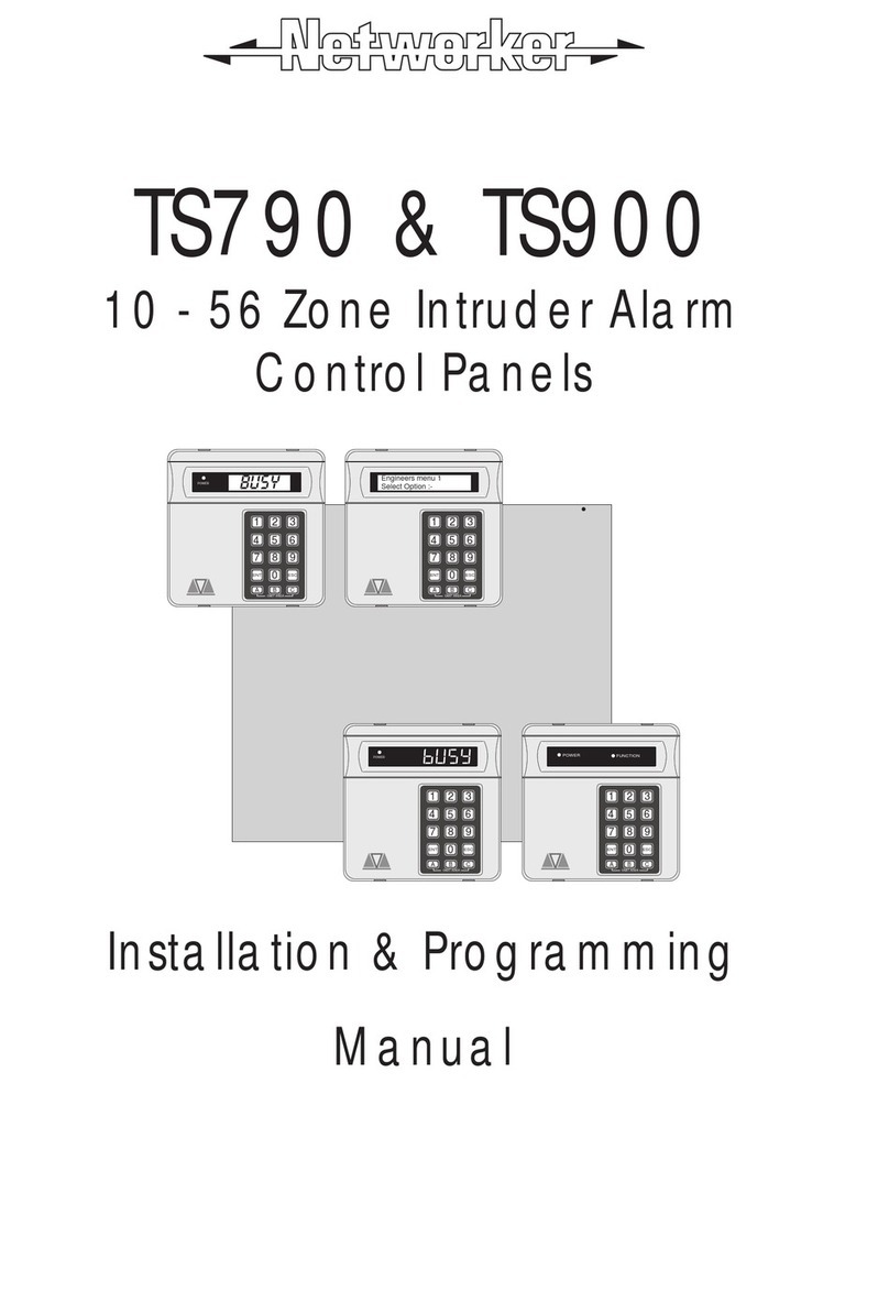
Networker TS790 User manual
Networker
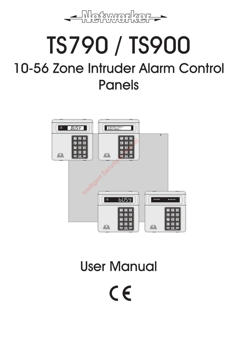
Networker TS790 Assembly instructions
Networker
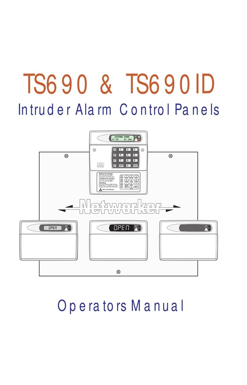
Networker TS790 User manual
Networker
Networker TS690 User manual

Networker
Networker TS700 Operation instructions
Networker
Networker TS690R Assembly instructions
Networker
Networker TS700 Operation instructions
Networker
Networker TS590 User manual
Popular Control Panel manuals by other brands
Olimpia splendid
Olimpia splendid B0872 Instructions for mounting and use
Extron electronics
Extron electronics MLC Plus 84 EU Setup guide
tecnoelettra
tecnoelettra TE805 manual
Elmes Electronic
Elmes Electronic STB12VM1 manual

ENDA
ENDA EOP4-057 Series installation instructions
Advanced
Advanced MxPro 5 Application note

