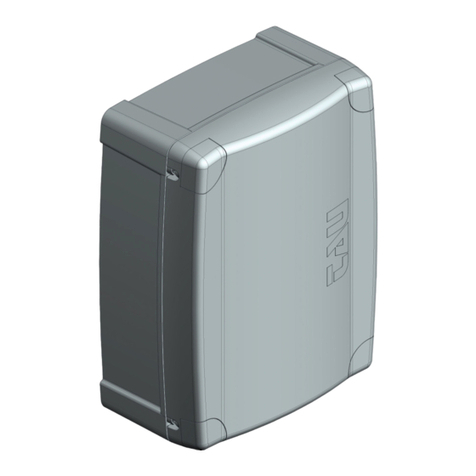
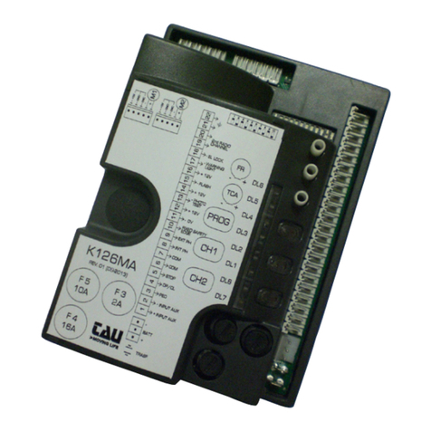
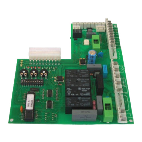
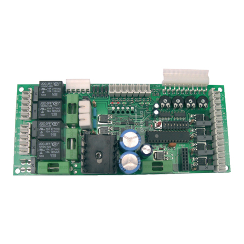
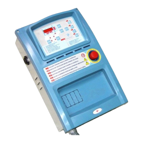
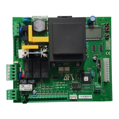
tau D703 User manual

1
D703
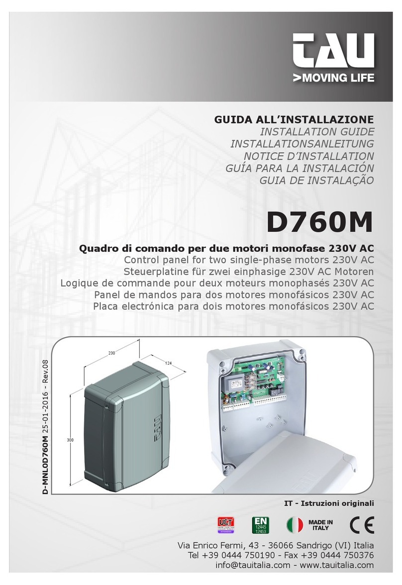
GUIDA ALL’INSTALLAZIONE
INSTALLATION GUIDE
INSTALLATIONSANLEITUNG
NOTICE D’INSTALLATION
GUÍA PARA LA INSTALACIÓN
D703
Quadro di comando per motore monofase-trifase 230/400 Vac
Control panel for 230/400 Vac single/three-phase motor
Steuerplatine für einphasigen-dreiphasigen 230/400 Vac Motor
Logique de commande pour moteur monophase-triphase 230/400 Vca
Panel de mandos para motor monofásico-trifásico 230/400 Vca
Via Enrico Fermi, 43 - 36066 Sandrigo (VI) Italia
Tel +39 0444 750190 - Fax +39 0444 750376
info@tauitalia.com - www.tauitalia.com
IT - Istruzioni originali
D-MNL0D703M 18-04-2014 - Rev.22
300
230
124

2
D703
230Vac
Power supply
400Vac
Power supply
Flashing
light
230Vac
max. 20W
Cap
12,5µF
2
MASTER 20T
BIG18QI
Thermal
protector
OLS
CLS
Common
Common
Photocell
Fixed safety edge
Common
Common
Photocell
Common
Open
Close
Stop
Ped
O/C
Open
Close

3
D703
VOLTAGE
SELECTION
400Vac
230Vac
Radio connector
Gate open
warning light
max. 3W
Antenna
2nd radio
channel
OLS = Open limit switch
CLS = Close limit switch
O/C =Open/Close
Ped = Pedestrian
Cap = Capacitor
TX = Transmitter
RX = Receiver
M = Motor
COM = Common
ENC = Encoder

11
D703
WARNINGS
Important information:
ATTENTION: Capacitors C5, C6 and C7 located over the fuse “F1A” may be live even after
the panel has been disconnected from the mains supply. Short the 2 terminals of each
with a screwdriver before touching them.
-
-
-
-
Whoever ignores such standards shall be held responsible for any damage caused by
the system!
Installation
To connect the power supply of control board in 400 V, use at least a 2.5 mm² cable,
max. 40 m long.
-
The product must be properly earthed and the safety regulations in force in the
country of installation must be observed.
ENGLISH

12
D703
CONTROL PANEL FOR 230/400V AC SINGLE/THREE-PHASE MOTOR
ATTENTION:
- do not use single cables (with one single wire), ex. telephone cables, in order to
avoid breakdowns of the line and false contacts.
- do not re-use old pre-existing cables.
TESTING
on when the commands they are associated with are active.
TECHNICAL CHARACTERISTICS
Power input to board
Maximum power 1,5 Kw ca.
Input voltage of motor circuits
Input voltage of auxiliary circuits
Logic circuit input voltage
Box protected to IP43
TERMINAL BOARD CONNECTIONS
Terminals Function Description
1 - 2 POWER SUPPLY
1 - 2 - 3 POWER SUPPLY
4 - 5 - 6 230-400V AC
MOTOR
for single-phase motors connect the capacitor between termi-
Note: select working voltage with jumper SW1 before
powering the board.
7 - 8 FLASHING LIGHT
already modulated for direct use. Flashing frequency increas-
9 - 10 STOP
automatic system. At the next command, the opposite opera-
ENGLISH

13
D703
9 - 11 PEDESTRIAN
opens the automatic system (by about 1 m) to allow pedestri-
12 - 13 OPEN/CLOSE -
12 - 14 OPEN -
12 - 15 CLOSE
16 - 17 FIXED SAFETY
EDGE
works during the opening phase by temporarily stopping the
16 - 18 PHOTOCELL
stops and then completely reopens. During the opening
phase it temporarily stops the gate until the detected obsta-
Note: the photocell transmitter must always be connect-
ed (terminals 27 and 28) as it is checked by the safety
system; the control unit will not work if it is disconnect-
ed. To disable the safety system move dip switch 6 to
OFF.
19 - 20 CLS (FCC)
19 - 21 OLS (FCA)
Note: the thermal protection (for MASTER20T and BIG-
18QI only) must be wired in series to the common of the
limit switch (terminal 19).
22 - 23 - 24 ENCODER
25 - 26 GATE OPEN
WARNING LIGHT
27 - 28 PHOTOCELL TX
29 - 30 PHOTOCELL
31 - 32 AERIAL
33 - 34 2nd RADIO CH
nd
Warning: to connect other devices to the 2nd Radio
Channel (area lighting, pumps, etc.), use an additional
auxiliary relay (with receiver connected).
CRECEIVER radio board connector.
ENGLISH

14
D703
LOGIC ADJUSTMENTS
TRIMMER
T.L.
T.C.A.
FR.
Note: turn the TRIMMER clockwise to increase adjustments; turn it anti-
clockwise to decrease.
Dip switches
1AUTOMATIC
CLOSING
On after opening, the gate automatically closes when the delay set on
Off
22 / 4 STROKE
On -
Off
in the same conditions, the same command sequence causes the
3MAN
PRESENT
On
Off
pushed, the automatic system performs a complete opening or clos-
Note: in the Man Present mode, the PP input (n° 13) is disabled, as is the radio receiver.
4
5ENCODER On -
Off
6PRE-FLASHING
FOTOTEST
On
Off
7
CLOSE
AFTER
PHOTOCELL
On
Off
8NO
REVERSE
On
Off
9
OPENING
PHOTOCELLS
OPERATION
On
during opening, the photocell cuts in to stop the gate until the ob-
stacle is removed. During closing, it stops the gate and then totally
reopens it.
Off during opening, the photocell does not trigger while during closing, it
10 BRAKING On
Off
Note: the braking system activates whenever the motor must stop (FCC - FCA - STOP
– change of direction) and reduces the inertia accumulated by the gear motor during
movement.
ENGLISH

15
D703
Clock function:
A timer can be connected to the open-close pushbutton in order to keep the gate open at certain
times during the day, after which it reverts to automatic closing.
DIAGNOSTICS LED
DL1 STOP button green LED signal
DL2 PEDESTRIAN button red LED signal
DL3 STEP BY STEP button red LED signal
DL4 OPEN button red LED signal
DL5
DL6 SENSITIVE EDGE green LED signal
DL7
DL8
DL9
MALFUNCTIONS: POSSIBLE CAUSES AND SOLUTION
The automation does not start
d_ Set the dip 3 (man present function) to OFF, dip 5 (encoder) to ON, dip 6 (phototest) to
The radio control has very little range
The gate opens the wrong way
ENGLISH

NOTES ON USING THE BIG18 WITH A SINGLE PHASE TO THREE PHASE INVERTER
1. With all power removed convert the D703 to a single phase control board by moving the wire one
terminal at SW1.
2. The motor wires connected at terminals 4, 5 and 6 on the D703 need to be connected to terminals
U, V and W on the inverter.
3. You will need two 240 volt relays. Connect terminal 4 (COM) on the D703 to one side of the coil of
both relays.
4. Connect 5 (OPEN) from the D703 to the other side of the coil of one relay.
5. Connect 6 (CLOSE) to the other side of the coil on the second relay.
6. Take the COM from the relay side of both relays to DCM (COM) on the inverter.
7. Take the N/O from the OPEN relay to FOR on the inverter.
8. Take the N/O from the COSE relay to REV on the inverter.
9. Connect 240 volts to the inverter at R, S and E and also to the D703 at terminals 1 and 2.
You are now ready to start testing your installation for motor for drive both ways and correct direction as
well as limits.
Table of contents
Other tau Control Panel manuals
Popular Control Panel manuals by other brands

Chipkin
Chipkin Mircom PRO2000 FS-8705-17 instruction manual
Texecom
Texecom Veritas 8 installation manual

Bavaria Yachts
Bavaria Yachts 301 instruction manual

Plymovent
Plymovent CONTROLPRO instructions
Siemens
Siemens Multi Panel MP270 SIMATIC HMI Equipment manual
AFL Hyperscale
AFL Hyperscale U Series installation guide
