NEULOG PHOTO GATE LOGGER SENSOR GUIDE
Velocity with a single gate:
Velocity with a single gate is the very basic velocity measurement
using only one photo gate sensor and any object with a known width.
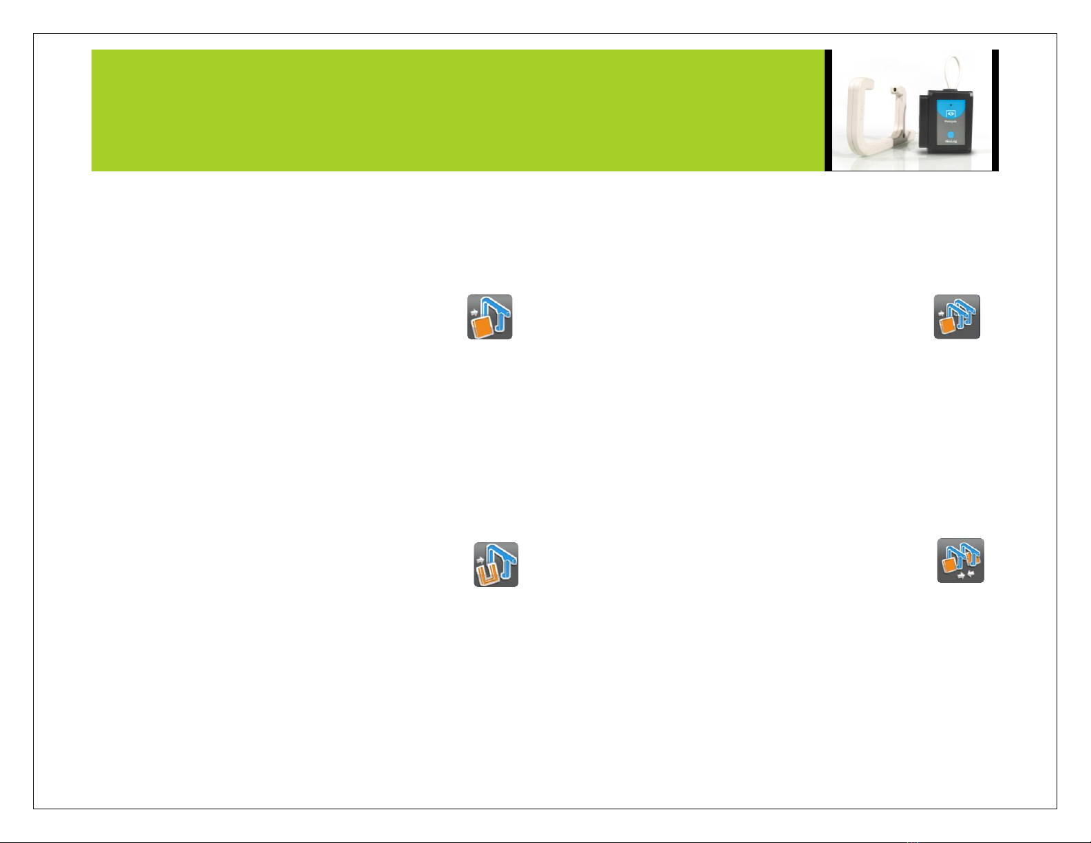
1. Click the “Run Experiment” icon in the NeuLog application and
select “Velocity with single gate”.
2. The figure shows the basic idea of what your
experimental setup should look like.
3. Measure and input the object width (in millimeters)
into the text field under the figure labeled “X (mm)”
4. Click on the "Record" icon.
5. For each time that the card passes through the photo gate, you
will receive the time it took for it to pass and its velocity.
Acceleration with a single gate:
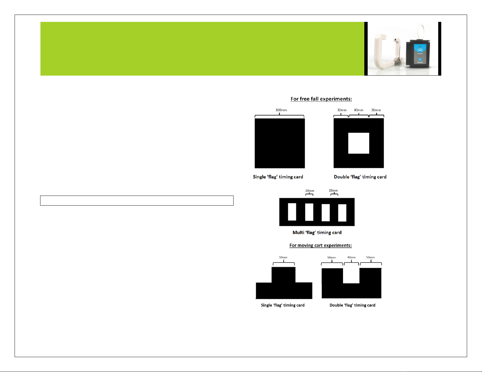
Acceleration with a single gate requires an object (or timing card)
with two flags (example shown above) with known widths.
1. Click the “Run Experiment” icon in the NeuLog application and
select “Acceleration with single gate”.
2. The figure shows the basic idea of what your
experimental setup and timing card/object should look
like.
3. Measure and input the width for both flags.
4. Click on the "Record" icon.
5. For each time that the card passes through the photo gate, you
will receive its acceleration.
Acceleration with two gates:
Acceleration with two photo gates requires two NeuLog photo gate
sensors and an object or timing card with a known width.
1. Click the “Run Experiment” icon in the NeuLog application and
select “Acceleration with two gates”.
2. The figure shows the basic idea of what your
experimental setup should look like.
3. Measure and input the width of your object (in
millimeters) into the text field under the figure labeled “X (mm)”.
4. Assign each of your photo gate sensors to both the “Sensor A”
and “Sensor B” position.
5. Click on the "Record" icon.
6. For each time that the card passes through the two photo gates,
you will receive its acceleration.
Velocity with two gates:
The velocity with two gates option is ideal for experiments which
examine collisions between two objects of known width and mass.
1. Click the “Run Experiment” icon in the NeuLog application and
select “Velocity with two gates”.
2. The figure shows the basic idea of what your
experimental setup should look like.
3. Measure and input the width and mass for both
objects passing through the photo gates.
4. Assign each of your photo gate sensors to both the “Sensor A”
and “Sensor B” position.
5. Be sure to space the photo gates far enough apart to allow for a
collision between the two objects before they rebound back
through the photo gates.
6. Click on the "Record" icon.
7. For each time the cards pass through the photo gates, you will
receive the velocity and momentum of each one of them.