GF 4630 User manual

*3-463X.090*
3-4630-X3.090 Rev 0 01/21
GF 4630 Free Chlorine Analyzer System
GF 4632 Chlorine Dioxide Analyzer System
CAUTION!
1. Follow instructions carefully to avoid personal injury.
2. Do not exceed the maximum pressure or temperature specifications.
3. In areas with elevated temperatures, mounting the Chlorine System in an outdoor box
may cause damage to the system if the enclosure's internal temperature exceeds the
temperature specification of the Chlorine Analyzer.
4. Do not alter product construction.
5. For use with clean fresh water only.
6. Disconnect from external power source before opening wiring enclosure.
7. This panel system may use AC voltages. Wiring should be done by qualified personnel only.
The GF 4630 System is EPA 334.0 Compliant.
English
Operating Instructions
The GF Chlorine Analyzer Systems are an integrated, all-in-one Chlorine Panel System
designed to measure Free Chlorine or Chlorine Dioxide in drinking water and clean,
fresh water treatment applications.
This manual applies to the 4630 Free Chlorine and 4632 Chlorine Dioxide Analyzer Systems.
Features:
• EPA 334.0 Compliant: The 4630 Free Chlorine System can be used for reporting chlorine
residuals in accordance with EPA Method 334.0.
• Complete Chlorine Analyzer System allows quick setup and easy installation. Connect to
a DC power supply and water source.
• Unique integrated clear flow cell combines sensors, flow regulator, filter and variable
area flow indicator in one compact unit.
• Built-in variable area flow indicator facilitates flow rate confirmation at a glance.
• Integrated flow regulator with removable filter accepts inlet pressures of 1 to 8 bar
(15 to 120 psi) while maintaining constant flow and minimal pressure to the sensors.
• Water flows vertically into sensor tip, eliminating bubble entrapment. Raised exit in flow
cell sensor chamber ensures sensors stay submerged even when system and flow is
turned off.
• Flow cell accommodates two sensors; one chlorine and an optional pH sensor.
• Automatic pH and temperature compensation or manual pH value input capability for
accurate free chlorine readings.
• Easy viewing of the transmitter via the bright backlit LCD display.
• Moisture-proof NEMA 4X wiring enclosure.
Do not use the 4630 in systems that could have the absence of Chlorine.
Additional information can be found in the individual product manuals,
refer to www.gfps.com.
Description
• English
• Deutsch
• Français
• Español
• Italiano
• 中文
WARNING: The GF Chlorine Analyzer (electrode) is designed to be used in a clean,
chlorinated flowing stream at all times. DO NOT use in applications where electrode could
be exposed to periods without chlorine.
Safety

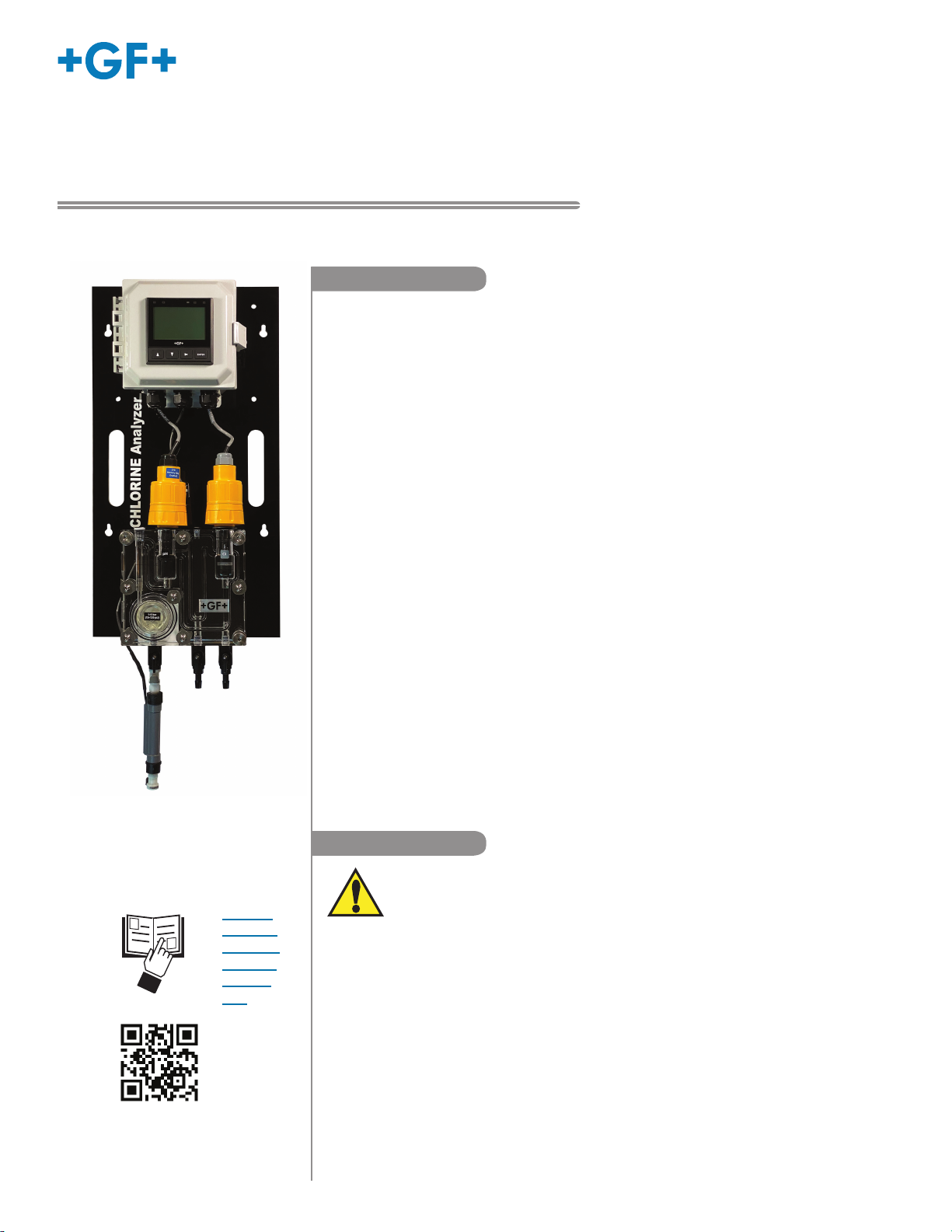
2463X Chlorine Systems Manual
Description ..................................................................................... 1
Warranty Information...................................................................... 2
Safety Information.......................................................................... 2
Chlorine System Dimensions / Specifications ............................... 3
Mounting / System Inventory ......................................................... 4
Quick Start ..................................................................................... 4
9950-3 Operation / Terminal Identification..................................... 5
Panel Assembly.............................................................................. 6
Component Identification: Flow Cell .............................................. 7
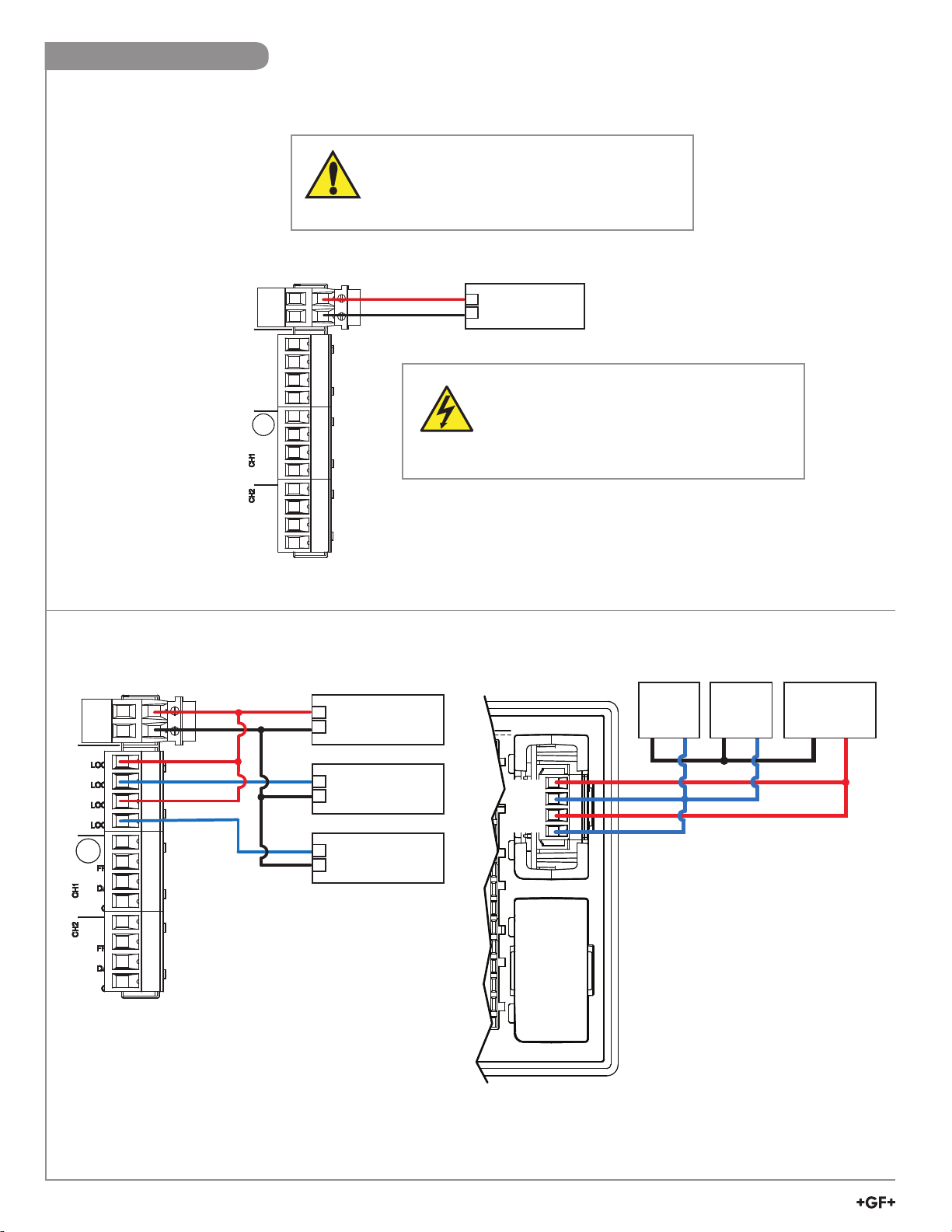
Wiring
3-9950-3 Input Power Wiring ..................................................... 8
4 to 20 mA Wiring Loop 1 & 2 .................................................... 8
9950 Dual Channel 4 to 20 mA Module..................................... 8
3-9950.393-3 Standard with 9950-3 .......................................... 9
3-9950.393-3 with internally powered flow switch ..................... 9
Sensor Wiring............................................................................. 9
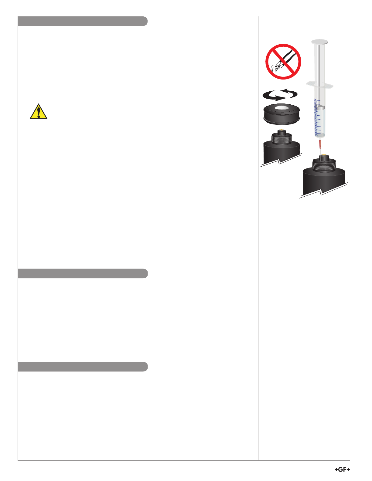
Chlorine Sensor Preparation / Maintenance ............................... 10
Sensor Installation.........................................................................11
Tubing Connections ..................................................................... 12
Water Flow ................................................................................... 12
9950-3 Chlorine Controller
Calibration ........................................................................... 13-15
Signal Type: Digital (S³L) ......................................................... 16
Module Installation ................................................................... 16
Plug-In Modules ....................................................................... 17
Loop and Modbus Modules ..................................................... 17
Relay Modes ....................................................................... 18-21
Chemical Guard ....................................................................... 19
Standard Relay Mode .............................................................. 20
Menu System
View Mode Overview ............................................................... 22
Menu Mode Overview.............................................................. 22
Password Overview ................................................................. 22
View Mode .............................................................................. 23-24
Calibration .................................................................................... 25
Chlorine Electrode Calibration ................................................. 25
pH Electrode Calibration.......................................................... 26
Input Menu .............................................................................. 27-28
4 to 20 mA Output (Loop Output)................................................. 29
Relay Menu
Chemical Guard Menu........................................................ 30-31
Standard Relay Menu .............................................................. 32
Option Menu........................................................................ 33-34
Modbus Menu ......................................................................... 35-36
9950 Field Software Upgrade / Updating the 9950 ..................... 37
Troubleshooting ...................................................................... 38-39
Calibration Error Messages ......................................................... 39
2630 Free Cl / 2632 ClO
2
Electrode ....................................... 40-42
2724 DryLoc pH Electrode........................................................... 43
pH System Calibration ............................................................ 44-45
Buffer Solutions............................................................................ 45
Electrode Storage ........................................................................ 45
463X Chlorine Analyzer Flow Cell ............................................... 46
O-ring Installation ......................................................................... 47
Flow Cell Assembly...................................................................... 48
Troubleshooting
463X Chlorine Analyzer ........................................................... 49
9950-3 Chlorine Controller....................................................... 50
9950-3 Error Messages ........................................................... 51
2630 Free Cl / 2632 ClO
2
Electrodes ...................................... 52
2751-7 pH Electronics.............................................................. 52
Specifications
9950-3 Chlorine Controller....................................................... 53
2650 DryLoc
®
Amperometric Electronics................................. 54
2751-7 pH Electronics.............................................................. 54
2630 Free Cl / 2632 ClO
2
Electrodes ...................................... 55
2724 DryLoc
®
pH Electrode ..................................................... 56
Notes............................................................................................ 57
Ordering Information .................................................................... 58
Warranty Information Table of Contents
Safety Information
Refer to your local Georg Fischer Sales office for the most
current warranty statement.
All warranty and non-warranty repairs being returned must
include a fully completed Service Form and goods must be
returned to your local GF Sales office or distributor.
Product returned without a Service Form may not be
warranty replaced or repaired.
GF products with limited shelf-life (e.g. pH, ORP, chlorine
electrodes, calibration solutions; e.g. pH buffers, turbidity
standards or other solutions) are warranted out of box but not
warranted against any damage, due to process or application
failures (e.g. high temperature,
chemical poisoning, dry-out)
or mishandling (e.g. broken glass,
damaged membrane,
freezing and/or extreme temperatures).
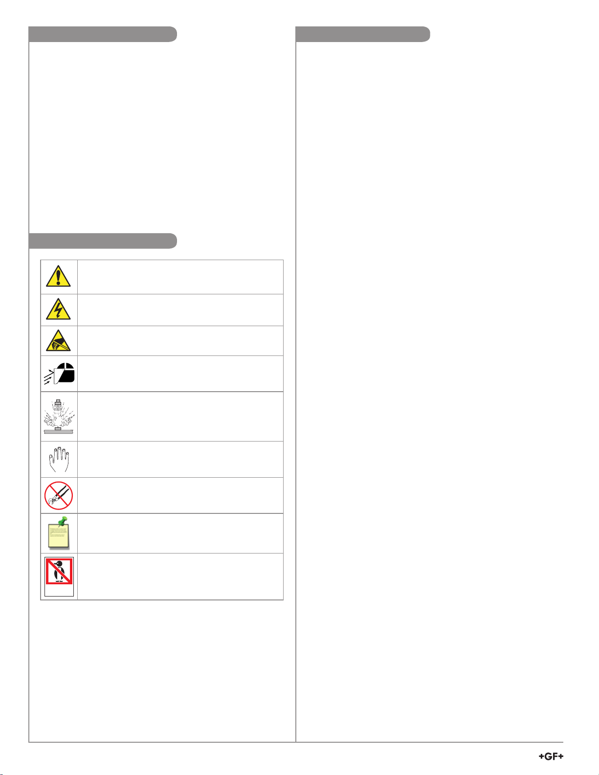
Caution / Warning / Danger
Indicates a potential hazard. Failure to follow all warnings
may lead to equipment damage, injury, or death.
Electrocution Danger
Alerts user to risk of
potential of injury or death via
electrocution.
Electrostatic Discharge (ESD)
Alerts user to risk of potential damage to product by ESD.
Personal Protective Equipment (PPE)
Always utilize the most appropriate PPE during
installation and service of GF products.
Pressurized System Warning
Sensor may be under pressure, take caution to vent
system prior to installation or removal. Failure to do so
may result in equipment damage and/or serious injury.
Hand Tighten Only
Overtightening may permanently damage product threads
and lead to failure of the retaining nut.
Do Not Use Tools
Use of tool(s) may damage product beyond repair and
potentially void product warranty.
Note / Technical Notes
Highlights additional information or detailed procedure.
DO NOT
FREEZE
Do Not Freeze
Products are temperature sensitive and may contain
freezable liquids. Freezing damage to pH, ORP, and
Chlorine electrodes voids product warranty.

3
463X Chlorine Systems Manual
305 mm (12 in.)
254 mm (10 in.)
330 mm (13 in.) 76 mm
(3 in.)
171 mm (6.75 in.)
Ø 7 mm
(0.27 in.)
25 mm
(1.0 in.)
Ø 13 mm
(0.52 in.)
Hand Holds
Safety Data Sheets (SDS) are available online at
www.gfps.com.
Dimensions System Specifications
General
Compatible GF Sensors
3-2630-1 Free Chlorine Sensor 0.02 to 2 ppm
3-2630-2 Free Chlorine Sensor 0.02 to 5 ppm
3-2630-3 Free Chlorine Sensor 0.05 to 20 ppm
3-2632-1 Chlorine Dioxide Electrode 0.02 to 2 ppm
3-2724-00 Flat pH Electrode
Free Chlorine.....................5.5 to 8.2 pH
(consult factory for pH above 8.2)
Chlorine Dioxide ................4.0 to 11 pH
Materials
Panel.................................Black acrylic
Flow Cell ...........................Acrylic
Wiring Enclosure ...............Polycarbonate
Wetted Materials
Flow cell, spacer rings .......Acrylic
Flow regulator housing.......Polycarbonate
Strainer, e-clip, regulator
spring, float .......................Stainless steel
Valves, vent.......................Polypropylene
Flow Cell O-rings,
diaphragm .........................EPR (EPDM), FKM
Chlorine electrode .............PVC, PTFE, FKM, Nylon, Silicone
pH electrode ......................PPS, Glass, UHMWPE, FKM
Sealing tape
(valves, plug, vent) ............PTFE
Plug...................................Polyethylene
Flow Switch .......................Polypropylene
Performance
System Inlet
Pressure Rating.................1 to 8 bar (15 to 120 psi)
Pressure Regulator............< 0.69 bar (10 psi) variation over
all ranges of flow and pressure
Flow tolerance ...................±15% or rated specification above
Flow rate limits ..................8 to 12 gph (US)
(30.24 to 45.36 LPH)
Electrical
DC Input (standard) ...........24 VDC nominal
(12 to 32 VDC, ± 10% regulated)
Environmental Requirements
Storage Temperature .........0 °C to 65 °C (32 °F to 149 °F)
Operating Temperature ......5 °C to 45 °C (41 °F to 113 °F)
Relative Humidity...............0 to 95%
Maximum Altitude ..............4000 m (13,123 ft)
Shipping Weight ................10 kg (22 lbs)
Enclosure ..........................NEMA 4X (with output wire
glands sealed)
Standards and Approvals
CE, UL, CUL, WEEE
RoHS Compliant
Manufactured under ISO 9001, ISO 14001 and ISO 45001.
China RoHS (Go to www.gfps.com for details)
Declaration of Conformity according to FCC Part 15
This device complies with Part 15 of the FCC rules.
Operation is subject to the following two conditions:
(1) This device may not cause harmful interference, and,
(2) This device must accept any interference received,
including interference that may cause
undesired operation.
CHLORINE Analyzer
34
2
1
1-8 bar
(15-20 psi)
279.4 mm
(11 in)
254 mm
(10 in)
330 mm
(13 in)
76 mm (3 in)
305 mm
(12 in)
148 mm
(5.83 in)

4463X Chlorine Systems Manual
Follow the steps below to set up a new Chlorine Analyzer System. Refer to the individual component manuals for detailed information.
Step 1. Mount the panel on a vertical flat surface using appropriate hardware.
Step 2. Open the wiring enclosure and wire input power.
(see page 8: Wiring Input)
Step 3. Wire any 4 to 20 mA and relay output.
Step 4. Remove sensor access plugs from the flow cell, see page 7.
If the optional pH sensor is NOT used, do not remove the left-side plug from the flow cell.
Step 5. Remove the protective cap from the chlorine electrode.
(Keep the electrode cap in a safe place for future use. It is recommended to use the cap to protect the sensor during
the removal of the electrode for cleaning or maintenance of the flow cell)
Step 6. Complete Sensor Preparation (see page 10) and install the chlorine sensor into the electronics.
(see page 11: Sensor Installation) Install the chlorine electrode into the flow cell.
The chlorine sensor is installed in the right-side access port, optional pH sensor is installed in the left-side access port.
NOTE:
Both the Chlorine and the pH electrodes are required to be calibrated for accuracy. Upon inital set up the electrodes
will need to be placed in a chlorinated flow stream for a minimum of 4 hours in a conditioning period. Calibration of
the Chlorine electrode is typically required every 14 to 21 days to comply with the EPA standard 334.0. The calibration
frequency of the pH electrode is application dependent and the intervals between calibrations must be determined by
the user of the system.
See page 10: Chlorine Sensor Calibration, for chlorine calibration and set up procedure.
Step 7. Repeat step 5 and 6 for the pH electrode.
Step 8. Remove the flow switch from the bottom of the flow cell and install into the flow cell , see page 7
Step 9. Install the influent water source to the "Inlet Port" nipple assembly of the flow switch. Install 3/8-inch tubing and secure
with a hose clamp.
(Not included. See page 12: Tubing Connections)
Step 10. Install 3/8-inch tubing and secure with a hose clamp on the "Drain" port and direct the tube to a proper drain.
(Not included)
NOTE: Drain line (zero pressure) must be lower than influent line to prevent back flow into the flow cell.
Step 11. Verify the inlet and drain ball valves are in the open position and the sample port is in the off position.
(See page 12: Tubing Connections)
Step 12. Turn on the influent water source and check the system for leaks.
Step 13. Apply power to the system and allow system to initialize. Calibrate per instructions.
(See page 10: Chlorine Sensor Calibration)
Do not turn on power at this time.
1. Chlorine panel assembly
a. Built-in pressure regulator 15 to 120 psi.
b. 3/8 inch hose barb connectors.
c. Flow switch
2. 1 each 2630 series Free Chlorine sensor or 2632
Chlorine Dioxide sensor; each with protective cap
a. 1 spare membrane cap
b. 2 bottles of electrolyte solution
c. 1 syringe needle (taped to bottle)
d. 1 syringe
3. 1 each Flat pH sensor 3-2724-00 (159 001 545)
(3-4630-13, -23, -33 and 3-4632-13 models only)
4. Manual package
a. English and Chinese panel assembly manuals
b. Wall mounting hardware
c. Drill template
5. Customer supplied
a. 3/8" hose input and drain
b. Hose clamps
Quick Start
System Inventory
• Bright light can promote algae growth. Indoor mounting
is recommended.
• If the system is mounted outdoors, an outdoor
enclosure for the whole system must be used to protect
the electronics and flow cell from light, rodents, insects
and dirt.
• Mount the panel according to local electrical, building,
and/or plumbing codes and seismic requirements.
• Use four 6 mm (¼ in.) diameter screws or bolts of
sufficient length to mount the panel to a sturdy vertical
surface. A mounting template is provided.
• Allow clearance on the sides and bottom for service to
the unit.
• Keep panel system electronics and enclosure away
from dripping water.
• The panel must be mounted vertically in an upright
position.
Do not mount in direct sunlight.
Mounting

5
463X Chlorine Systems Manual
ENTER
UP, DOWN keys
Scroll through Menu options or adjust values during editing
Press both together to exit a menu or escape without saving
RIGHT key
Select item or character to edit
ENTER key
Access menus
Save changes
9950-3 Operation
ENTER
4
00.00 99.99
00.00 99.99
CH1 9999.9
9999.9
9999.9
9999.9
CH2
UOM
UOM
UOM
UOM
Relay 1
Indicator LED
Relay 2
Indicator LED
Backlight Sensor
(do not block)
Bar Graph
Channel 1
display area
Menu Navigation Keys
Relay 3
Indicator LED
Relay 4
Indicator LED
Units of Measure
(mg/l/ppm)
Numeric
Values
or labels
Bar Graph
Channel 2
display area
Numeric
Values
or labels Units of Measure
(pH)
DC Power Terminals
Current Loop Outputs 1 and 2
Current Loop Outputs 3 and 4
3-9950.398-2
Channel 1 Input
Chlorine Sensor Electrode
Optional Modbus Module
3-9950.395-M
Channel 2 Input
pH Electrode
USB Port
Relay Module
3-9950.393-3
9950-3 Terminal Identification

6463X Chlorine Systems Manual
ENTER
34
2
1
1-8 bar
(15-20 psi)
Amperometric chlorine
sensor electronics
3-2650-7 (159 001 670)
Flow cell block
Vent
Cap
Wiring enclosure
Flow rate indicator
Flow range limits
Flow regulator with strainer
Inlet port
Drain port
9.5 mm
(3/8 inch hose)
Sampling port
pH sensor
electronics
3-2751-7 (159 001 957)
pH electrode
3-2724-00 (159 001 545)
Quick disconnect plug
9.5 mm (3/8 inch hose)
2000-3825*
Quick disconnect
2000-2525*
Hose barb
9.5 mm (3/8 inch) 2000-3804*
Ball valve
9.5 mm (3/8 inch) 4300-5225*
Chlorine electrode
3-2630-X (Free Chlorine)
3-2632-1 (Chlorine Dioxide)
* Contact factory for quote
Panel Assembly
Chlorine Controller
3-9950-3 (159 001 955)
Flow cell O-rings
Flow switch
3-4630.395 (159 001 960)

7
463X Chlorine Systems Manual
Flow cell front block
Disc spring (2700-0003)*
Spacer ring
Stainless steel filter
Pressure regulator
Pressure regulator outer O-ring (large)
Pressure regulator outer O-ring (small)
Flow cell O-rings (4 segments)
Flat washer
Flat washer*
Disc spring (curved washer)
Knurled thumb nut (1700-2512)*
Flow cell bolt (2490-0554)
Included in kit 3-4630.390
Item Quantity
Flow cell nut 6
Flat washer 15
Disc spring 9
Knurled thumb nut 3
Flow cell bolt 6
Flow cell nut
Flat washer
Flow cell back block
Regulator Assembly
(3-4630.391)
(159 001 689)
Flow Cell
Rebuild Kit
(3-4630.390)
(159 001 688)
*Not included with
3-4630.392 (159 001 690)
3-4630.392
(159 001 690)
Component Identification: Flow Cell

8463X Chlorine Systems Manual
Wiring
3-9950-3 Input Power Wiring
DC POWER
+
–
Black
Red Power Supply
12 to 32 VDC
Red
Red
+
–
PLC or
Recorder
–
PLC or
Recorder
+
Blue
Blue
MODULE 1
MODULE 2
Power
Supply
–+
Loop B+
Loop A–
Loop B–
Loop A+
PLC
or
Recorder
–+
PLC
or
Recorder
–+
Red
Red
Blue
Blue
9950 Dual Channel 4 to 20 mA Module4 to 20 mA Wiring Loop 1 & 2
3-9950-3
WARNING
DO NOT connect AC power to the DC version
THE 3-9950-3 MUST BE POWERED BY
12 - 32 VDC at 0.5 A.
DC POWER
+
–
Black
Red Power Supply
12 to 32 VDC
Caution:
For DC power input and loop current regulated
voltage, use UL60950-1 or UL61010-1 certified
power supply. Power supply shall also be rated
for operation at 4000 m altitude.

9
463X Chlorine Systems Manual
Wiring continued
3-9950.393-3 Standard with 9950-3
The alarm is OFF during normal operation,
and will go ON when the relay energizes
according to 9950 Relay settings.
RELAY MODULE
X
SW1
SW2
SW3
SW4
SW COM
No Connection
Binary Input 1
Binary Input 2
Binary Input 3
Binary Input 4
N/O 1
N/C 1
COM 1
N/O 2
N/C 2
COM 2
Relay 1
Relay 2
DC
Power Supply
Chemical
Dosing pump
Chemical
Dosing pump
Flow Switch Assembly
(159 001 960)
Black
Black
Red
Red
Blue
Blue
N/O 1
N/C 1
COM 1
SW4
SW COM
N/O 2
N/C 2
COM 2
SW3
SW2
SW1
X
RELAY 1
RELAY 2
BINARY INPUT 3
BINARY INPUT 1
No Connection
BINARY INPUT 2
BINARY INPUT 4
AC or DC
power
ALARM!
Black
Black
Black
Red
3-9950.393-3 with internally powered flow
switch from factory
Technical Notes:
• Route sensor cables away from AC power lines.
• Connect the silver (shield) wire to earth ground in case
of EMI noise interference.
2751-7 with 2724 pH Electrode
Black
Red
White
DC POWER
2650-7 with 263X Chlorine Electrode
Black
Red
White
CH1CH2
Sensor Wiring

10 463X Chlorine Systems Manual
Initial Fill Procedure:
When adding electrolyte, be prepared for an accidental spill.
Working near a sink is recommended.
1. Remove the protective bottle from the end of the electrode.
2. Remove the membrane cap from the front of the sensor.
Note: When new sensors are shipped, the membrane cap is not tightened to
the sensor.
3. Fill supplied syringe with electrolyte solution.
Additional caution should be taken when handling Chlorine Dioxide electrolyte solution.
4. Place the electrode on a level surface.
5. Insert syringe needle fully into one of the eight electrode holes while injecting with
electrolyte solution. Slowly injecting the electrolyte solution into the sensor to avoid
introducing air bubbles. The electrode holds approximately 14 milliliters of solution.
Slowly fill until solution begins to flow out of holes. Do not allow the solution to run
down the electrode and wet the electrical contacts in the DryLoc connector.
6. Slowly screw on the membrane cap finger tight. Do not use tools. To avoid damage
and contamination, do not touch the white membrane surface on the membrane cap.
NOTE: See page 40 for additional 2630, 2632 information.
• Chlorine sensors are shipped without internal electrolyte solution.
• Prior to installation and supplying power, Chlorine sensors must be filled with the
appropriate internal electrolyte solution.
• Verify the correct electrolyte solution is utilized with the corresponding sensor.
• Free Chlorine and Chlorine Dioxide sensors require different electrolyte solutions.
2630 Free Chlorine Electrode
2632 Chlorine Dioxide Electrode
NOTE: Inspect and change the
membrane cap if damaged.
See page 41, Maintenance, for
cleaning procedure.
A new chlorine electrode or one that has had the membrane cap changed must be
calibrated. See page 13, 9950-3 information on calibration of the chlorine sensor. A
diethyl-p-phenylenediamine (DPD) colorimeter test kit (not included) is required for sensor
calibration. A sample is taken and analyzed with the DPD test kit, then this value is
entered into the 9950-3.
• A new system requires an inital 4 hour conditioning.
• Calibrate after a membrane cap change (requires 2 hour stabilization time).
• Calibrate after the internal electrolyte is replaced (requires 2 hour stabilization time).
• Check calibration 24 hours after sensor is placed in service.
• Check calibration weekly to monthly depending on process requirements.
The sensor membrane and internal electrolyte solution must be replaced over the life
of the electrode. To maintain accurate chlorine measurements, GF recommends that
the internal electrolyte be replaced every 3 to 6 months, or when Chlorine readings drift
low and/or cannot maintain a calibration longer than 5 days. Actual interval between
maintenance of the sensor will be dependent on the application, chlorine level and
contaminates in the water. See page 41; Maintenance and Storage.
Keep spare membrane caps available. Membrane caps carry no warranty.
To maintain accurate chlorine measurements, GF recommends the internal electrolyte be
replaced and the gold-plated sensor electrode be properly polished every
3 to 6 months. See page 41.
Chlorine Sensor Calibration
Chlorine Sensor Preparation
Chlorine Sensor Maintenance
CAUTION:
DO NOT touch the gold-plated tip
or the membrane of the sensor.
1
2
3
4
5
6
7
8
9
10
ml
Avoid skin or eye contact with electrolyte solution.
Wear rubber gloves and goggles.
*Safety Data Sheets (SDS) are available online at www.gfps.com.
CAUTION! DO NOT touch the gold tip or the membrane of the sensor.

11
463X Chlorine Systems Manual
IN
OUT
pH Cl
IN
OUT
pH Cl
• Remove sensor access plugs from the flow cell.
Note: Chlorine Sensor Preparation must be completed prior to installation, see 10.
• Holding the 3-2751-7 (159 001 957) or 3-2650-7 (159 001 670) electronics inverted, open the DryLoc®connector by
turning the upper locking ring ¼-turn counter-clockwise.
• Insert the electrode facing up. Turn the locking ring ¼-turn clockwise to lock the electronics in place.
• The mechanism will “click” when it is locked.
• Install the complete electrode assembly into the flow cell and ensure the key on the electrode aligns with the key slot on
the flow cell.
DryLoc®Connection to Sensor Electronics
Locking Ring
Lock
Lock
3-2630-X
3-2632
Chlorine Electrode
3-2724-00
(159 001 545)
pH Electrode
3-2650-7
(159 001 670)
Chlorine Electronics
3-2751-7
(159 001 957)
pH Electronics
Avoid skin or eye contact with electrolyte solution.
Wear rubber gloves and goggles. Safety Data
Sheets (SDS) are available online at
www.gfps.com.
Lubricate the DryLoc®O-ring only.
Do not lubricate the sensors body O-ring.
Turn by hand. Do Not Use Tools.
Do Not Drop or Strike the Membrane.
GF 3-2630-X
GF 3-2632
Chlorine Electrode
GF 3-2724-00
(159 001 545)
Flat pH Electrode
GF 3-2751-7
Electronics
GF 3-2650-7
pH Electronics
Sensor Installation
Lubricate O-rings with a
non-petroleum based, viscous
lubricant (grease) compatible
with the system.
Lubricate O-rings with a
non-petroleum based, viscous
lubricant (grease) compatible
with the system.
Do not lubricate
this O-Ring

12 463X Chlorine Systems Manual
IN
OUT
ClpH
OK
MIN
MIN
MI
N
MA
X
MA
M
A
Flow Rate
The flow rate is in the proper range when the float is
between the Min. and Max. markers on the flow cell.
The flow range limits are 30.24 to 45.36 L/h (8 to 12 gal/h).
• Use suitable 9.5 mm (3/8 in) ID tubing that is rated for
your inlet pressure.
• Use hose clamps.
• Remove the Flow Switch from the three ball valves
located on the bottom of the flow cell.
• Insert inlet quick connect into the mating connector on
the flow cell.
Valve position for start up and normal use.
Note: Turn off inlet valve first when stopping water flow.
• The drain tube must be positioned lower than the influent
water source to allow proper flow through the flow cell.
The flow cell must drain by gravity, not system pressure.
• When testing, allow the sample to flow for a few seconds
before collection.
Inlet Quick Release Connection
Press down gray plunger to release. Water flow is
automatically shut off when disconnected.
For Low Flow applications (flow less than 1 bar/15 psi), the
Flow Regulator can be removed and the flow adjusted using
the Flow Cell ball valve. NOTE: The inlet hose barb will also
need to be changed. (Contact factory for details.)
IN
OUT
Inlet Drain
(to outlet)
Sampling port
(flow off)
Flow Switch and Tubing Connections
Water Flow

13
463X Chlorine Systems Manual
9950-3 Calibration
Both the Chlorine and the pH electrodes are required to be calibrated for accuracy. Upon inital set up the electrodes will need to be
placed in a chlorinated flow steam for a minimum of 4 hours in a conditioning period. Calibration of the Chlorine electrode is
typically required every 14 to 21 days to comply with the EPA standard 334.0. The calibration frequency of the pH electrode is
application dependent and the intervals between calibrations must be determined by the user of the system.
In order to achieve the most accurate chlorine measurement, after the minimum 4 hour conditioning period, calibration must be
performed in the following specific order:
• Temperature
• pH electrode (Free Chlorine only)
• Chlorine electrode
NOTE: The Temperature element only requires calibration one time during initial commissioning. Once calibrated the Temperature
element is calibrated for the life of the chlorine electrode.
Chlorine sensor temperature element calibration
The temperature element inside the chlorine sensor needs to be calibrated. Use a reference thermometer to verify the actual
temperature of the sample. This value is then entered into the calibration screen of the Temperature Calibration menu.
Tip: Remove the pH electrode from the flow cell and insert the reference thermometer. If no pH sensor is being used
(ClO2system), remove the cell plug to insert the thermometer. Replace the plug after calibration.
pH electrode calibration
It is highly recommended to perform a two point calibration of the pH electrode using a pH buffer 7 and pH buffer 4 or 10. The pH
buffers' temperatures should be close to the system water temperature for an accurate calibration. Once a successful calibration
is performed, the 9950 will automatically time stamp the "Last CAL" display with the date of calibration. The user can add a date to
the "NEXT CAL" display which will generate a "Calibration Due" icon across the pH channel (CH2).
Chlorine sensor
Calibration must be performed to every new chlorine sensor (FCl or ClO2) and any time a membrane cap or internal electrolyte is
replaced. With the chlorine sensor attached to the 2650 electronics (with system power on) and placed in a chlorinated flow steam
for the minimum of 4 hour conditioning period, the temperature and chlorine In-Process Calibration needs to be performed.
Once a successful calibration is performed the 9950 will automatically time stamp the "Last CAL" display with the date of
calibration. The user can add a date to the "NEXT CAL" display which will generate a "Calibration Due" icon across the chlorine
channel (CH1).
NOTE: It is advised to return 24 hours after the initial Chlorine calibration to verify and recalibrate if necessary.
Temperature Calibration
ENTER
4
CH 1 FREE CI
HOLD OUTPUTS
OFF
CAL
LOOP
RELAY
OPTION
INPUT
TEXT 3
CH 2 pH
CH 1 FREE CI
ENTER
CH 1 FREE CI
TEMPERATURE
SET
CH 1 FREE CI
C
25.00
ENTER
TEXT 3
CH 2 pH
CH 1 FREE CI
5s
to Save +
Display returns to
calibration display
C
+25.00
+25.30

14 463X Chlorine Systems Manual
CH 2 pH
pH STANDARD
SET
CH 2 pH
pH STANDARD
SET
ENTER
CH 2 pH
pH SLOPE
SET
TEXT 3
CH 2 pH
CH 1 FREE CI CH 2 pH
HOLD OUTPUTS
OFF
CH 2 pH
RAW - 3 mV
6.80
CH 2 pH
MM/DD/YYYY
LAST CAL
CH 2 pH
MM/DD/YYYY
NEXT CAL
to edit to edit
Place electrode tip in
saturated pH 7.0 buffer.
to edit
Use the arrows to modify
the pH value, matching
the buffer solution.
to Save
ENTER
Place electrode tip in
saturated pH 4.0 buffer.
Use the arrows to modify
the pH value, matching
the buffer solution.
to Save
+
Display returns to
calibration display
RAW - 3 mV
6.80
+07.01
to edit
CH 2 pH
pH STANDARD
SET
RAW 173 mV
4.80
+04.80 CH 2 pH
pH SLOPE
SET
TEXT 3
CH 2 pH
CH 1 FREE CI
CH 2 pH
MM/DD/YYYY
NEXT CAL
to edit
MM/DD/YYYY
NEXT CAL
MM/DD/YYYY
ENTER
to Save
pH Electrode Calibration
Calibration

15
463X Chlorine Systems Manual
Calibration
Chlorine Electrode Calibration
CH 2 pH
pH STANDARD
SET
CH 1 FREE CI
HOLD OUTPUTS
OFF
ENTER
TEXT 3
CH 2 pH
CH 1 FREE CI
ENTER
TEXT 3
CH 2 pH
CH 1 FREE CI to edit CH 2 pH
pH STANDARD
SET
CH 1 FREE CI
ZERO CAL
SET
0.0 PPM
nA
- .01
Place electrode tip
into DI water.
CH 2 pH
pH STANDARD
SET
CH 1 FREE CI
IN PROCESS
SET
to edit
x3
Test sample with an
external DPD test
instrument.
to Save
Modify Chlorine PPM
value to match DPD
reference.
RAW 100.5 nA
+ 002.25
+ 002.25
+
Display returns to
calibration display
CH 1 FREE Cl
MM/DD/YYYY
NEXT CAL
MM/DD/YYYY
NEXT CAL
MM/DD/YYYY
ENTER
to Save
CH 2 pH
pH STANDARD
SET
CH 1 FREE CI
IN PROCESS
SET
CH 1 FREE Cl
MM/DD/YYYY
LAST CAL
CH 1 FREE Cl
MM/DD/YYYY
NEXT CAL

16 463X Chlorine Systems Manual
The plug-in modules may be installed either before or after the
base unit is mounted. If the 9950-3 Base Unit will be mounted
using the provided quick clip mounting bracket, install plug-in
modules first with power disconnected.
To install modules:
Remove power from the 9950-3. Carefully align pins and
connectors (do not bend connecting pins) and push module firmly
into place, then attach with screw(s) for Relay Modules only.
CAUTION
Exercise care when installing modules.
Do not bend connecting pins.
To move modules:
Remove power from the 9950-3.
For Relay Modules:
Unplug connectors, remove screw(s), and carefully pull
module straight out from the base unit. Do not bend the
connecting pins.
For Dual Channel 4 to 20 mA, and Modbus Modules:
Unplug connectors and squeeze the two retaining tabs while
pulling module out of 9950-3.
WARNING
Relays may be connected to external
high-voltage power sources or multiple power
sources creating an electrocution hazard.
Module Installation
CAUTION
Avoid Electrostatic Discharge (ESD).
MODULE 1
MODULE 2
Rounded
Corners
Dual Channel
4 to 20 mA Module
Important!
Ensure the rounded
corner of the module is
alligned with the rounded
corner of the module slot
before installing
9950
• The input terminals on the 9950-3 carry Digital (S
3
L) serial data from the sensor.
• Do not route sensor or output cables in conduit containing AC power wiring.
Electrical noise may interfere with sensor signal.
• Routing cable in grounded metal conduit will help prevent electrical noise and
mechanical damage.
• Seal cable entry points to prevent moisture damage.
• Only one wire should be inserted into a terminal. Splice double wires outside the
terminal.
• The TOTAL cable length from I/O devices to the transmitter must not exceed
305 m (1000 ft).
• In case of noise interference, ground the sensor SHIELD wire to a local earth ground at
a point near the sensor.
• Consult the sensor manual for additional wiring information.
• The maximum cable length of the Digital (S
3
L) bus varies depending on the types
of sensors connected and the size of the conductors in the cable. For best results,
determine the maximum cable length for the system before routing cables.
In case of noise
interference, connect
the cable shield to earth
ground.
Maximum total cable length
of the Digital (S3L) Bus:
The quality of the cable used
in the bus determines the
maximum length.
The maximum cable length
may not exceed
305 m (1,000 ft),
regardless of current
requirements.
Signal Type: Digital (S3L)

17
463X Chlorine Systems Manual
•
Minimize handling of the plug-in modules to reduce the possibility of damage due to ESD.
•
Handle modules by the edges.
Never touch any exposed circuitry or contacts.
•
Wear an anti-static wristband or stand on an anti-static mat, or keep one hand touching a
properly grounded pipe or other piece of properly grounded metal when handling modules.
CAUTION
Avoid Electrostatic Discharge (ESD).
Standard modules for the 9950-3:
a. Base Unit (required) 3-9950-3 159 001 841 Base Controller, no modules
b. Relay Module 3-9950.393-3 159 310 270 Relay Module
c. Module 1 3-9950.398-2 159 001 848 Dual Channel 4 to 20 mA
Output Module
Optional module for the 9950-3:
d. Module 2 3-9950.395-M 159 001 905 Modbus Module (optional)
Each item is ordered separately. Modules are field-replaceable at any time.
See Module Installation (pg. 11) and Ordering Information (pg. 68) sections for more details.
Plug-In Modules
a
b
c
d
Mfr. Part No. Code Description
3-9950.398-2 159 001 848 Dual Channel 4 to 20 mA Current Loop Output Module
3-9950.395-M 159 001 905 Modbus Module
Loop and Modbus Modules
Dual Channel 4 to 20 mA Module
Two additional 4 to 20 mA passive current loop outputs in a single module, allows up to six current loop modules in the
9950-3 Chlorine Controller.
Modbus Module
The Modbus Module connects the 9950-3 to serial RS485 Modbus automation networks. The Modbus Module will allow for
PLCs and SCADA Systems to query the current readings, channel status, state of the relay and 4 to 20 mA outputs, along
with status of the 9950-3 Chlorine Controller and Modbus communications.
Detail programming information is available in the 9950 Modbus Programming Manual, available at www.gfps.com.
Default Communication Parameters
ModBus Address 95
ModBus Termination Off
ModBus Mode RTU
ModBus Baud Rate 19.2K
ModBus Parity Even
ModBus Endian Big

18 463X Chlorine Systems Manual
NOTE:
• The four red Indicator LEDs on the front panel of the 9950-3 show the status of relays
1, 2, 3, & 4. The LEDs will activate with or without a relay module installed.
• Hysteresis and time delay are adjustable for each relay.
The 9950-3 has a slot for an optional Relay Module for the module listed on page 17.
• The four Binary Inputs can detect if an external switch is open or closed. The switch state
can be used to enable or disable the relays in the module
. The four binary inputs only
control relay activation and are not considered an input measurement.
This is standard on the 9950-3.
• A flow switch must be wired into Binary input #1 to allow access to the Chemical Guard mode
of the 9950-3.
• Dry-contact relays are electromechanical switches with a moving contact armature. They are
suitable for many general-purpose applications, AC or DC, including AC loads up to 250 V.
For wiring information, refer to the Relay Wiring section, page 8.
Switching active loads (usually inductive) can cause contact arcing
sufficient to damage the relays.
The RC Filter Kit or “snubber” (part number 3-8050.396) is available
as an accessory to reduce or eliminate these damaging effects.
Recommended for inductive loads greater than 50 VAC (remote relays,
solenoids, pumps, etc.)
CAUTION
Keep relay wiring
separate from
electrode and signal
wiring to prevent
interference and
damage to the
9950-3 Transmitter.
CAUTION
The 3-9950.393-3 module can be set to supply power to the external switch/
sensor. If an externally powered sensor is connected with the 3-9950.393-3
module, set the power switch to the EXT position. The module can power external
sensors by switching the power switch to the INT position. Maximum power that
can be drawn from the module is 6mA at 30 VDC. Important for externally powered
switches/sensors to ensure the output signal is within the allowable range for the
3-9950.393-3.
3-9950.393-3
Int / Ext
Switch EXT
INT
Binary Input Ratings
Maximum Input voltage
(without damage) 30 VDC
Minimum Input voltage
(without damage)
-5 VDC
(no operation below
0 VDC)
Maximum input voltage for
signal “Off” (low or "0") 1.5 VDC
Minimum input voltage
for signal “On” (high or "1") 3.0 VDC
Maximum current draw for
signal “0” (low) <500 ADC
Minimum current draw
for signal “1” (high) 500 A
Typical current draw
for signal “1” (high)
6.0 mA at 30 VDC,
4.8 mA at 24 VDC,
2.4 mA at 12 VDC,
1.0 mA at 5 VDC
INT
EXT
Power
Switch
Relay Modes

19
463X Chlorine Systems Manual
The Chemical Guard prevents overdosing of oxidant type chemicals (Chlorine) whose concentration
varies based on the pH level of the application.
The Chemical Guard is only accessible in the relay menu when used in conjunction with a flow switch
(GF option) that is wired to the Binary Input #1 of the 3-9950.393-3 relay module.
When the Chemical Guard function is selected, Relay 1 is automatically defaulted to control and adjust
the Oxidant chemical (Chlorine) and Relay 2 is defaulted to control and adjust the pH level of the
application.
The control logic (Fig #) will always interrupt (disable) Relay 1 if the pH requires adjusting. Once the pH
is corrected, Relay 1 is then available to add additional oxidants to the application.
The Chemical Guard allows Relay 1 and Relay 2 to be independently programmed as a low set point,
high set point or a proportional pulse output.
Example: Maintain a
pool's chemistry using
two dosing pumps at
pH 7.2 and chlorine at
3.0 ppm
1. Press and hold ENTER for 3 seconds
2. Go to the Relay Menu by pressing then ENTER
3. Display shows "FLOW SWITCH" NO, press and change to YES,
Press ENTER to save
4. Press screen should show "RELAY CHEMICAL GUARD" OFF
5. Press and change to YES, press ENTER to save
6. Press screen should show "Oxidizer" Mode OFF
7. Press and select LOW
8. Press x2 to set POINT DISPLAY
9. Press to enter the LOW SET POINT value 3.0 ppm, press ENTER to save
10. Press then press to enter ON DELAY time of 15 seconds, press ENTER to
save
11. Press then press to enter an OXIDIER HYSTERESIS of 1.0 ppm,
Press ENTER to save
12. Press x3 screen should show pH ADJUST Mode OFF
13. Press to change the Mode to HIGH
14. Press x2 then press to enter HIGH SET POINT of 7.5
15. Press then press to enter ON DELAY time of 15 seconds, press ENTER to
save
16. Press then press to enter pH ADJUST HYSTERESIS of 0.3 ppm
17. Press +at the same time to go back to the VIEW Mode
Flow Switch Enabled
Chemical Guard ON
Is there flow?
Is the pH correct?
Is the Chlorine level
correct?
Disable R1 and R2
Turn on R2
Disable R1
YES
YES
YES
YES
YES
No
No
No
Turn on R1
Disable R2
Relay Modes
Chemical Guard

20 463X Chlorine Systems Manual
Standard Relay Mode
Example: Set a relay
R1 to turn on at a low
setpoint of 2.0 ppm
with a time delay of 15
seconds and turn off at
3.0 ppm.
Remember,
SET LOW + hysteresis = OFF
Relay 1 Source = CH1 Primary
Relay 1 Mode = Low
R1 Set Low = 2.0
R1 Hysteresis = 1.0
R1 on delay = 15.0 sec
Set your relay functions to your own application requirements.
1. Press and hold ENTER for 3 seconds
2. Go to the Relay Menu by pressing then ENTER
3. Press the to select desired source. You will be asked to enter a
code or password. Select source and press ENTER to confirm
4. Press to enter the relay MODE selection screen
5. Press and then to select R1 MODE LOW. Press ENTER to
confirm
6. Press to R1 SET LOW. Press to enter PPM value of 2.0
7. Use the and to change Setpoint. Press ENTER to save
8. Scroll to the R1 HYSTERESIS menu
9. Press to edit
10. Set the hysteresis for this relay. Set the value to 1.0 ppm
11. Press ENTER
12. Scroll down to the R1 ON DELAY menu
13. Press to edit
14. Set the turn-on delay in seconds for the relay: 15.0
15. Press ENTER Then
16. Exit to View Mode
Relay function can be tested in the RELAY menu
Once a setting is saved it becomes immediately active.
Relay Modes
• Binary
When the relay source is set to “Binary", the Binary Inputs
can sense if the input is ON (Closed) or OFF (Open). The
four binary inputs only control relay activation and are not
considered a measurement source. Each binary mode is
independent and each of them can be assigned to a relay
mode.
Example: Binary Input
A 3-4630.395 Flow Switch is
mounted in the Chlorine flow
cell.
The flow switch will prevent the
relay(s) from activating if the
flow to the cell is interrupted.
• Error Mode
Relay activated when any related failures occur for the system.
Other manuals for 4630
1
This manual suits for next models
1
Table of contents
Other GF Measuring Instrument manuals