Newacalox 878D User manual

NEWACALOX 878D/8786D
SMD REWORK STATION User Manual
welcome to use newacalox 878D soldering station. This manual will show
the parameters, performance, usage and precautions of this machine.
If you have any problem of usage or any suggestion about this soldering
Warranty :
1: HEAT GUN Accessories and soldering iron accessories if broken within
a month can send a replacement by connecting with after service.
2:If the gadgets in the package are lost, please contact us for reissue,
thank you.
3:We will guide you carefully about the use and maintenance of this
product.
Our products 878D soldering station use the brush-less fan,and long life
and low noise.It is very good for repair phone and PCB.Please read this
operating instruction manual carefully before using the serial products of our
company.Thank you!
If you like our product, can you share your experience or review for it on
Amazon. It can help us a lot,thanks in advance.
Matters Needing Attention :
1. Be careful not to burn yourself when using it because it is hot.
2. make sure that you have connected the heat gun handle to the station before turn
on it. And Only can unplug the heat gun after trun off station. Otherwise, it will burn
out the heat gun handle and damage the main machine of the rework station.
3. When you stop using soldering station, please don’t disconnect the plug
immediately when you turn off the power button of soldering station. And this
soldering station will automatically shut down as soon as it stop blowing wind.
Otherwise you will shorten the life of soldering station. And please remove the
plug if you do not use this station for a long time.
4. when using this station for the first time, please use it in a ventilated environment.
Keep the heat gun away from your eyes. When the oil is exhausted, the heat gun
will no longer have an unpleasant smell.
Features
1. Comfortable portable handhold blower and the Digital LED display.
2. Microcomputer control,warming-up quickly.
3. Adjust button for air flow and temperature control .
4. come with three kinds of nozzles(big 8mm, medium 5mm and small 3mm)
replacement part.
5. Come with replacement Heating Core for long time use
6. Offer Auto Cool Down Function (“stand by” mode)
7. This product is ESD-protected.
8. High-quality resistance good for long service life.
9. Green lines and high-quality silicone body offer good heating for extend life
and save power.
10. Handle with sensor switch. Taking the handle, the station will enter the
working mode. Put back on the bracket, it will enter stand by mode.
Specification
Model
NEW878D
Type
LED indicator light
Power
Consumption
700W
Blower Fan
Brush-less ball fan
Amount Of Wind
120L/min(MAX)
Temperature
Range
100--480℃
Discharge
Feature
LED indicator light
Temperature
Range
±1℃
Size
10.2*6.5*5.8’’
Weight
5.62LB
Noises
<45db
Usage
Essential product for cell phone repair, laptop repair, circuit boards, etc.
Suitable for unsoldering multiple components,such as SOIC CHIP QFP PLCC
and BGA etc (especially for flat cables and cable connectors).International
standard heater for convenient use and exchange, noise-reducing and
space-saving. heat gun part broken can be resend.

Operation Instruction
HEAT GUN PART
1.Assemble the station with the heat gun and soldering accessories.
2.Make sure turn all the on-off button at off station, and then plug in the power
supply.
3. set the temp of blower by press the “↑ or ↓” buttons,press up button to
raise the temperature. Set up the temp and take up the handle, the gun will
warm-up.
4.Set the air flow by rotating the air flow setting knob.
Stand-by mode:
when turn off the power ,the screen will displays”----”,it represents the rework
station enter stand-by mode.it will cool down gradually.
when you put the handle back on the holder, the station will enter stand-by
mode.
4.Temperature memory function:When you turn off the station at 400 degree
centigrade, when you turn on next time, it will auto heat up to the 400 degree
centigrade.
5.When you finish your work, put the blower handle back on the holder,the
station will stop warming automatically. And when the temp is lower than
100℃,the station will show “---”,that meant the tool is going to enter standby
state
6.To switch off the power and unplug if there is no operation for a long period of
time.
IRON PART
1.Assemble the station with the heat gun and soldering accessories. Make
sure turn all the on-off button off, and then plug in the power supply.
2.Turn the iron on by pressing on/off button.
3.Set the temperature by rotating the temperature setting knob. Turn off when
you stop your work and storage it when all the soldering iron is cool down.
4.Temperature memory function:When you turn off the station at 400 degree
centigrade, when you turn on next time, it will heat up to the 400 degree

centigrade.
FAQ:
Q:Low Airflow when “Air” Dial is Turned Up
A:If you are getting low airflow when the “Air” Dial is turned up, make sure
that you have the nozzle securely attached. With the nozzle, you will get more
air flowing through the hot-air rework station’s handle.
S-E Error
“S-E” usually means Sensor Error. It’s a common error. Sometimes it goes
away after messing with the dial and the temperature will display properly
again. Other times it indicates that the heat sensor is failing. The rework station
might be able to be revived by removing and re-attaching the heater. Another
tech support rep thinks it’s oxide building up on the connections. This results in
fooling the controller into thinking the heater has failed.
H-E Error
Units displaying the “H-E” usually means there is a heating error. It might be
that there is something with the heating element failing or not connected
properly. Try checking the connections to see if the heating element needs to
be re-seated. Last resort is getting a replacement heating element. A last
resort is getting a replacement heating element.
Air Turned Too High
If your air flow is turned up too high, it is quite possible that you will start seeing
small projectiles shooting away from your board. Those are your parts. We
recommend starting at a lower air flow and moving up as your needs require.
Destroying a PCB
If you sit too long on a given spot on a PCB while working with hot-air, the glue
that holds the copper layer to the FR4 laminate underneath lets go and comes
out as black goo. The green solder mask on the top side also begins to come
off. Because we don’t have Smell-a-vision yet, we can try to describe the smell
- it’s horrendous. It smells like burning electronics (surprise) but the smell
seems to cling to your skin and clothes. Not cool. So practice and don’t be
surprised if you smell bad things with your first couple re-work attempts.

Pulled Pads
When checking to see if a part is ready to move, we recommend nudging the
part gently. If you push too hard, you can pull the pad.
Nozzles don't fit
The nozzles produced are all tight. In order to avoid being too easy to fall off during use,
there is a danger of burns.
You can take it out with pliers. After a few more uses, there will be no this problem again,
or you can use pliers to adjust the size of the nozzle.
A:What's It Good For?
Q:Hot-air rework stations can be very handy. As mentioned above, they are a
crucial tool when it comes to reworking a board. The term rework just means
you are refinishing or repairing an already reflowed board, and it is a term
commonly used in the electronics world. Just think of it as doing any work to
the board that wasn’t involved in the actual production process. Here are some
common rework scenarios:
Polarized Components - Parts that have been placed incorrectly (backwards,
shifted x degrees off). These include ICs, diodes, some capacitors, connectors,
etc.
Tombstone Parts - This is when a part (usually a resistor or capacitor) reflows
only on one side. The part usually sticks strait up resembling a tombstone.
Cold Joints - This is similar to a tombstone except the parts might not be
sticking strait up, making it harder to see the connection that is not being
made.
Removing Defective Parts - Sometimes, during the IC manufacturing process,
errors can arise and go unnoticed. These ICs are then placed on perfectly
good PCBs. Hot-air is great for replacing these bad parts.
Missing Components - The smaller the component, the easier it is for it to
disappear. This can happen before or during reflow, resulting in a spot where
something should be, but isn’t. Hot-airing a new part in its place is a snap with
this rework station.
Unintentional Solder Jumpers - If too much solder or solder paste is used, the
result can be jumpers on one or more of your surface mount IC’s legs. Hot-air

can sometimes be used in conjunction with a flux pen to remove these pesky
buggers.
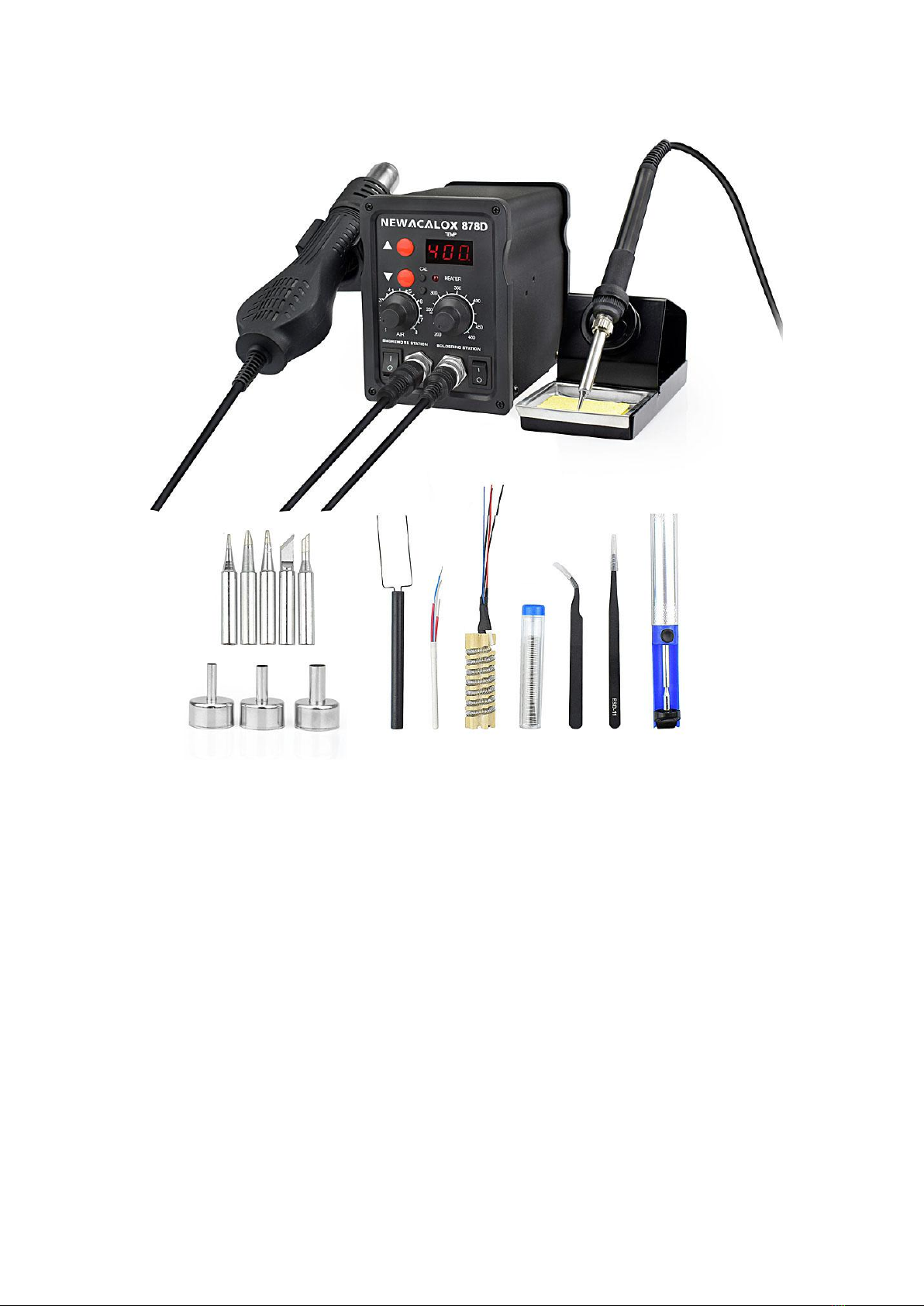
Use of accessories
2 x Tweezers(fine tip curved,fine tip straight ): Pick up small items.
1 x IC Extractor: Small hook for easy extracting IC and installation
1 x Desoldering Pump: remove extra solder.
1 x Heating Core for air blower: when the air blower was burns out artificially ,
you can replace the heating core and continue to use it
1 x Power cord * 1 US(length:100mm): connecting the power source
3 x Nozzles( 3.2mm,5mm,8mm): Meet the different diameter of the operation
1 x Heating Core for soldering iron: when the soldering iron was burns out
artificially , you can replace the heating core and continue to use it
5 x Soldering Tip((I K B 3C 1.6D): Meet the different need of the operation
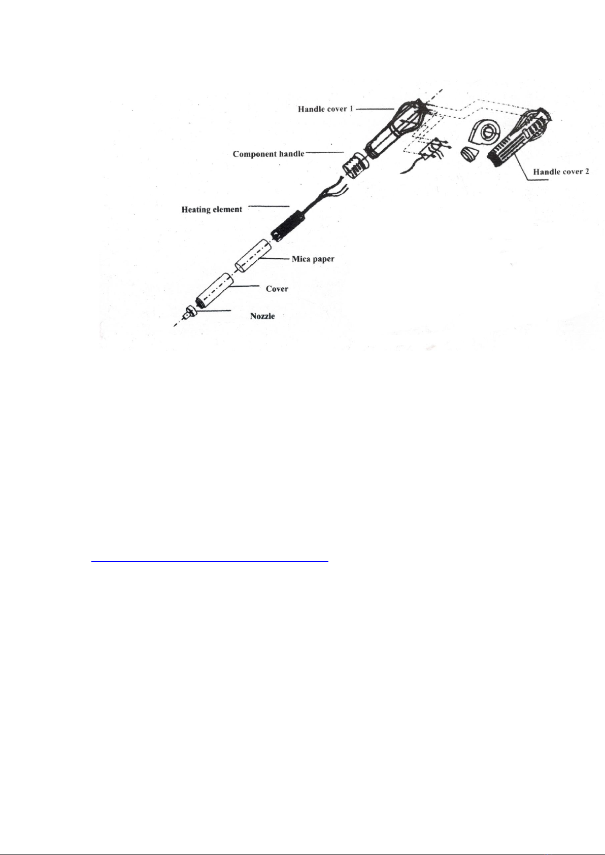
Replacement of Heating Element.
1.Please replace the heating core of soldering iron in rework station cooling
condition. prevent burns.
Most soldering stations utilize a ceramic heating element to generate the heat
required for soldering. As with any resistive heating element, the element will
eventually burn out. The majority of Circuit Specialists-brand soldering stations
include a replacement heating element at no additional charge. The procedure
for testing and replacing this heating element will be described for Circuit
Specialists CSI Station 1A.
The first operation should be to verify that the heating element is indeed
burned out. The resistance of the heating element should measure between 19
and 23 ohms. A reading of several thousand ohms or more would be indicative
of a burned out heating element. On the 1A soldering station the heating
element is connected between pins 1 and 2 on the soldering iron receptacle. If

the resistance measures correctly, the temperature sensor should then be
measured. This measurement is obtained between pins 4 and 5 on the
soldering iron receptacle and should be between 1.2 to 1.5 ohms. If any of
these resistance values are incorrect, the heating element should be replaced.
The hand piece should be disassembled after unplugging it from the main unit.
Remove the copper retaining nut before turning it counterclockwise until it is
free of the threads on the handle. Remove the tip enclosure, soldering tip, and
tip lock by pulling them forward off the hand piece. Next, unscrew the plastic
retaining nut by turning it counterclockwise until it is free of the plastic threads
on the handle. Now push the heating element out from the handle’s body to
expose the connections to the cord and a small PCB. Unsolder the four wire
connections —RED/RED and BLUE/WHITE — of the old heating element and
remove it from the PCB. Be sure to note the location of each of the four wire
connections on the PCB.
Detach the metal protector located at the bottom of the old heating element
and attach it to the bottom of the new heating element. The new heating
element may now be soldered onto the PCB in the same location as the
element that was removed. Solder one of the two RED wires from the heating
element to the RED wire from the cord on the PCB, and then solder the
remaining RED wire from the heating element to the BLUE wire from the cord
on the PCB. (Note: There is no polarity requirement for the two RED heating
element wires, so they may be interchanged with no detrimental effect on the
operation of the soldering station. The sensor wires, however, are polarity
sensitive and must be attached as outlined next.)
Solder the BLUE wire from the heating element to the GREEN wire from the
cord on the PCB, and solder the WHITE wire from the heating element to the
WHITE wire from the cord on the PCB. The heating element PCB assembly
may now be re-inserted into the handle. Make sure that the PCB is secured in
the notch at the mouth of the main handle. The plastic retaining nut may now
be re-installed on the base of the handle and tightened down. To complete the
re-assembly operation, slide the tip holder on (making sure that the smaller
end isintroduced first), insert the soldering tip, and secure the assembly with
the tip enclosure and copper nut. The resistance measurements outlined
above should now be performed again to verify the connections.
This procedure illustrates the steps required to test and replace the heating
element in CSI Station 1A, but the same procedure can be applied to almost
any soldering station with a resistive heating element. Be aware that a
replacement handle is available for all Circuit Specialists soldering stations at a
very reasonable cost if the user does not wish to perform the above listed
service.
Attention:
1.Do not damage the ground connection on the steel tube when replace the
heating element of heat blower.
2.Do not damage the connection on the Unsoldering Equipment during the
replace the heating element of soldering iron
3.The link assembly on the handle cover shall be put inside of fixing hole on
the steel tube during the installing of handle components.
Product link:
https://www.amazon.com/dp/B077WDXD6H
This manual suits for next models
1
Table of contents
Other Newacalox Soldering Gun manuals

Popular Soldering Gun manuals by other brands


Genesis
Genesis GHG1500A Operator's manual

Pace
Pace MBT250E-SDSoftGround Installation, operation & maintenance manual

Sealey
Sealey SD250K quick start guide

Harbor Freight Tools
Harbor Freight Tools Schneider 58005 Owner's manual & safety instructions

TOOLCRAFT
TOOLCRAFT ST50-D operating instructions

Hakko Electronics
Hakko Electronics C5045 quick start guide


