Parts Identification
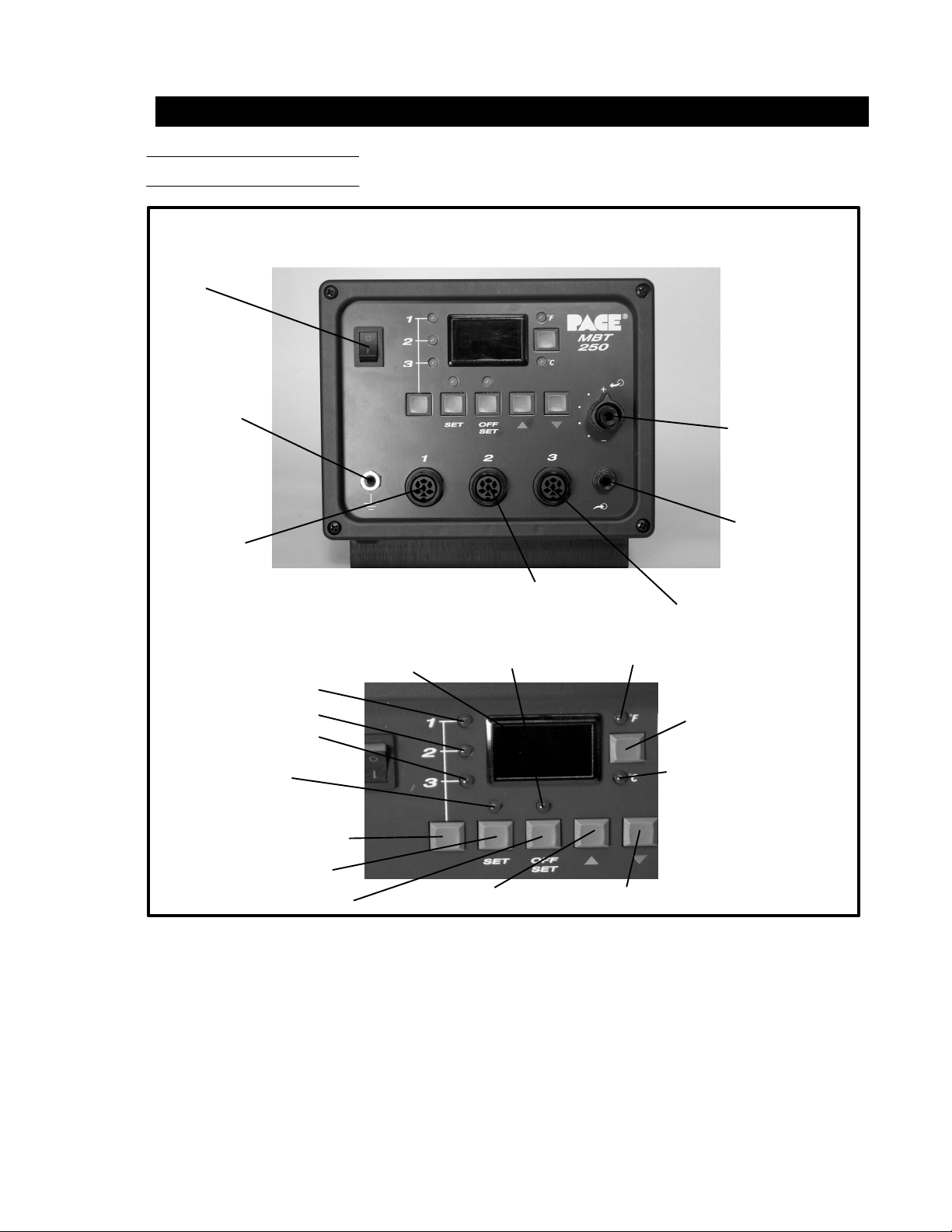
Listed below is a description of the system power source parts. Use Figures 1 & 2 as a guide.
1. CH1 POWERRECEPTACLE-Providespower,tipground,sensingcircuitryandfingerswitchconnection
from MBT system to handpiece connected to Channel 1 (CH 1).
2. CH2 POWERRECEPTACLE-Providespower, tipground,sensingcircuitryand finger switchconnection
from MBT system to handpiece connected to Channel 2 (CH 2).
3. CH3 POWERRECEPTACLE-Providespower,tipground,sensingcircuitryandfingerswitchconnection
from MBT system to handpiece connected to Channel 3 (CH 3).
4. POWER SWITCH - Turns system ON ("1") and OFF ("0"); controls input power to the system.
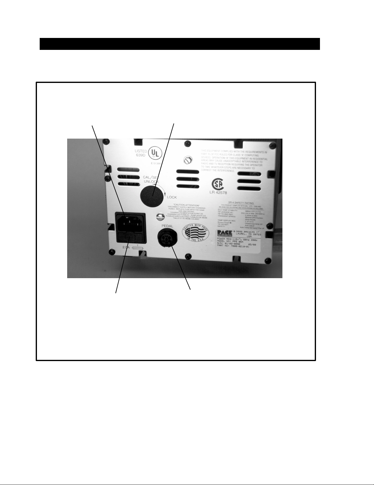
5. AUTOSNAP-VACPORT-Quickconnectfittingprovidesquick-risevacuumforSodr-X-Tractor,
ThermoPik and Dual ThermoPik handpieces. Vacuum is present when handpiece finger switch or optional
foot pedal is actuated. Vacuum ceases 1.2 seconds after switch (or foot pedal) released.
6. CONTROLLABLE PRESSUREPORT-Quickconnectfittingwithadjustablevalvewhichprovides
variable air flow for Mini ThermoJet handpiece (inHot Jet Mode) and Sodr-X-Tractor handpiece. Air
pressure is present when handpiece finger switch or optional foot pedal is actuated. Air pressure ceases
1.2 seconds after switch (or foot pedal) is released.
7. DIGITALREADOUT-ProvidesathreedigitdisplayoftheCurrentChannel(channelwithilluminatedLED;
CH1,CH2orCH3) temperature information. This includes:OperatingTipTemperatureinTemperature
Display Mode (normal operation), Tip Offset Constant in Tip Offset Mode, Set Tip Temperature in Tip Set
Modeand other information inCalibration(CAL) Mode.
8. °F /°C KEY - Selects°F or °C displayofSet and Operating Tip Temperaturesand Tip Offset Constants.
9. °F LED - Illuminates when Set\ Operating Tip Temperatures and Tip Offset Constants are displayed in °F.
10. °C LED - Illuminates when Set\ Operating Tip Temperatures and Tip Offset Constants are displayed in °C.
11. CH 1 LED - Illuminates when Channel 1 (CH 1) is the “Current Channel” i.e., the channel (with connected
handpiece\tip) whose temperature information is displayed on the digital readout.
12. CH 2 LED - Illuminates when Channel 2 (CH 2) is the “Current Channel” i.e., the channel (with connected
handpiece\tip) whose temperature information is displayed on the digital readout.
13. CH 3 LED - Illuminates when Channel 3 (CH 3) is the “Current Channel” i.e., the channel (with connected
handpiece\tip) whose temperature information is displayed on the digital readout.
14. CH SELECT KEY -SelectstheCurrentChannel(among"ActiveChannels"i.e.,thosewithaconnected
handpiece).
15. TIP SET KEY - Allows the operator to adjust the Set Tip Temperature for the handpiece\tip combination
connected to the Current Channel. Places the system in the Tip Set Mode.
7