XTRONIC 4040-PRO-X User manual


- 1 -
SPECIFICATIONS
Model XTR-4040-PRO-X
Power Consumption 700 Watts
Power Cord USA Type B - 3-pin Grounded Plug
Voltage AC 110V 60Hz
Current ≤ 8 Amps
Fuse 15 Amps
Dimensions 9.0 L x 9.5” W x 5.5” H
Weight 7.5 lbs
Working Environment 32°F ~ 104°F / 0°C ~ 40°C
Storage Environment -4°F ~ 176°F / -20°C ~ 80°C
Storage Humidity 35% - 45%
HOT AIR REWORK
Hot Air Gun Total Output 600W
Airflow Type Brushless DC Vortex Blower
Airflow Volume 55 L/Min
Airflow Velocity 3.4 M/S
Programmable Air Flow 20-100
Temperature Range 212°F ~ 932°F / 100°C ~ 500°C
Temperature Stability ± 1°C
Cord Length ≥ 33.2 in
Cord Material Silicone
Sound Intensity ≤ 69dB
SOLDERING IRON
Soldering Iron Total Output 75W
Temperature Range 392°F ~ 932°F / 200°C ~ 500°C
Temperature Stability ± 1°C
Output Voltage 24 V AC
Tip Impedance < 2Ω
Cord Length ≥ 33 in
Cord Material Silicone

- 2 -
PACKAGE CONTENTS
• 700 Watt Main Power Unit
• 75 Watt Soldering Iron with Ergonomic Grip
• Deluxe Upright Tower Soldering Iron and Hot Air Gun Holder
• Soldering Cord Extension Holder
• Wet Sponge Tip Cleaner
• 700 Watt Hot Air Gun
• Hot Air Gun Holder (on side of main unit)
• 5 - Sizes/Styles of Hot Air Gun Nozzles
• 3 Straight Air - 5mm, 7mm, & 10mm
• 2 Spiral/Cyclone Air - 8mm & 10mm
SAFETY PRECAUTIONS
1. Always use a grounded outlet for the unit.
2. Always turn the power off and unplug the unit when not in use.
3. Never use the soldering iron or hot air gun near any flammable
substance, material, or gas.
4. Never touch the metallic components of the soldering iron or hot
air gun while the unit is on. They are extremely hot and will cause
serious burns instantly.
5. Always turn the power off, unplug the unit, and let it fully cool down
before attempting to replace any parts (tips, heating element, etc.)
6. Use only genuine replacement parts for this unit.
7. Do not use the unit for any application other than soldering.
8. Do not tap the soldering iron against the work bench to remove
residual solder.
9. Do not modify the unit in any way.
10. When replacing consumable parts, only use approved
manufacturer parts.
11. Do not get the unit wet or use when your hands are wet.
12. The soldering process can produce smoke - ensure the area is
well ventilated.

- 3 -
PANEL DIAGRAM
SOLDER IRON
▲▼
HEAT GUN
TEMP - - -
SOLDER IRON
TEMP - - -
12
3
4 5
6
7
8
9
AIR
▼ ▼
▼▼
II
I II 4040-PRO-XIX-TRONIC
10
1. Soldering Iron Power Switch
2. Hot Air Gun Power Switch
3. Air Flow Control Knob
4. Temperature Adjustment Buttons for Hot Air Gun
5. Soldering Iron Temperature Display
6. Hot Air Gun Cord Receptical (Hard-wired)
7. Soldering Iron Cord Receptical
8. PID (Proportional-Integral-Derivative) Indicator
9. Temperature Adjustment Knob for Soldering Iron
10. Hot Air Gun Temperature Display
Hot Air Gun
Side Holder
Hot Air Gun -
Vertical Position

- 4 -
INITIAL SET-UP
1. Attach the hot air gun holder onto the left side of the unit - the
screws can be found in the unit. (This can also be attached to the
right side of the unit if desired. To do this, detach the bracket from
the holder, flip it around and reattach it, then mount it to the right
side of the main unit.)
2. Place the hot air gun in the holder on the left side of the unit or in
the vertical position in the upright tower holder.
3. Plug the Soldering Iron into the front cord receptacle on the right
side of the unit and tighten the ring nut.
4. Place the soldering iron in the soldering iron area of the upright
tower holder provided.
5. Plug the 3-Prong AC cord into a 110/120V grounded outlet to
prevent electric shock or injury.
6. Turn ON the power switches for both the hot air gun (I) and
soldering iron (II) on the front of the unit.
7. Turn the main power on with the power switch on the back of the
unit. When the unit is first turned on “C - C” or “F - F” will briefly
show on the top display to indicate if the unit readouts are in
Celsius or Fahrenheit respectively. Then both LED displays will
show “---”.
SOLDERING IRON
1. The bottom display will show the current temperature of the
soldering iron when it is turned on and will immediately start to
heat up to the last set temperature.
2. To adjust the temperature of the soldering iron, turn the knob “+”
or “-” to increase or decrease the temperature. The soldering
iron can be set bewteen 392°F ~ 932°F / 200°C ~ 500°C. The
display will change to show the temperature being set, once the
temperature set as been chosen it will switch back to show the
actual temperature of the soldering iron.
3. To turn the soldering iron off, turn off the Ipower switch on the front
of the unit.

- 5 -
HOT AIR GUN
1. The top display will show “SLP” when the hot air gun is in its holder
and in sleep/standby mode.
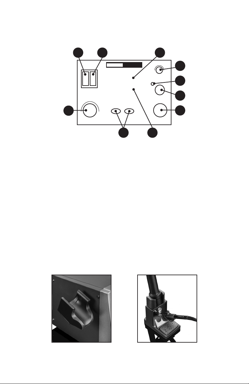
2. Push the Hot Air Temperature Adjustment Buttons (▲ or ▼ ) in the
middle unit to set the hot air gun temperature. The hot air gun can
be set between 212°F ~ 932°F / 100°C ~ 500°C.
3. Turn the Air Flow Control Knob to adjust the airflow for the hot air
gun. This can be set from 20 - 100.
CAUTION
When using a temperature higher than 300°C on the hot air gun the
air flow should be set at 45 or higher. This will prevent damage to
the hot air gun and increase the life of the heating element.
4. When the hot air gun is removed from the holder it will start
blowing air and ramp up to the programmed temperature and air
speed quickly.
5. When the hot air gun is not in use always place it back in the side
holder or in the vertical position in the upright tower holder. When
the hot air gun is placed in one of these holders, it will start going
into the Auto Cool Down and Sleep/Standy mode immediately. The
hot air gun will continue blowing air until the temperature gets back
down to 100°C and then the airflow will stop and the hot air gun will
go into sleep/standby mode.
Note: When the hot air gun is initially returned to either of these holders,
the air flow may increase noticeably while the hot air gun is
cooling down and going into sleep/standby mode. This is a safety
feature built into the unit.
6. When the hot air gun is removed again from either of these holders
it will start blowing air and ramp up to the programmed temperature
and air speed again quickly.
7. To turn the hot air gun off, turn off the II power switch on the front
of the unit.
Note: Do not unplug the unit or shut off the Main Power Switch on
the back of the unit until you have placed the hot air gun in the
holder and it has cooled down and the air has stopped blowing
automatically - this allows a full cool down of the hot air gun.
When the unit is not in operation and has fully cooled down, turn the unit
off with the power switch located on the back of the unit and unplug from
the outlet.

- 6 -
FEATURES
SOLDERING IRON SLEEP FUNCTION
When the soldering iron is placed in the holder, the iron will go
into sleep mode after a few minutes (depending on the number of
minutes that have been programmed for this feature). The display
will show “SLP” to signify this and the temperature of the soldering
iron will ramp down to 392°F / 200°C. When the soldering iron
is removed from the holder to use again, the temperature of the
soldering iron will quickly ramp back up to the set temperature.
Note: The unit will NOT go into sleep mode unless the soldering iron is
in the holder.
SETTING THE SOLDERING IRON SLEEP TIMER
1. Ensure the soldering iron and the hot air gun are in their respective
holders and that the main switch on the back of the unit is OFF.
2. Turn on the power switches for both the hot air gun and soldering
iron on the front of the unit.
3. With both of those switches ON, press and hold both of the
Function setting buttons (also known as the Hot Air Temperature
Adjustment Buttons) while turning ON the unit with the main switch
on the back.
4. The bottom display will show the number of minutes that sleep
timer is currently set at.
5. To adjust the sleep minutes rotate the Soldering Iron Temperature
Knob. This can be set from 0 to 30 minutes.
6. When the number of minutes is set, press the right (▲) button and
the setting will be saved.
Note: Setting the sleep timer at “00” will turn the sleep function off and
the unit will NOT go to sleep regardless of how long the unit sits
idle in the soldering station holder. It is not recommended to turn
the sleep timer off for normal use. The use of the sleep timer will
help extend the life of the heating element and tip if the unit is left
on for long periods of time.

- 7 -
HOT AIR GUN COOL DOWN SLEEP/STANDBY FUNCTION
When the hot air gun is placed in the side holder or the
vertical position in the upright tower holder (see page 3), it will
automatically go into Cool Down mode. When the hot air gun
is initially returned to either of these holders, the air flow may
increase noticeably while the hot air gun is cooling down and going
into sleep mode. This is a safety feature built into the unit.
TEMPERATURE CONVERSION
1. Ensure the soldering iron and the hot air gun are in their respective
holders and that the unit is OFF.
2. Turn ON the power switches for both the hot air gun and soldering
iron on the front of the unit.
3. With both of those switches ON, press and hold the right Function
setting button (also known as the ▲ Hot Air Temperature Button)
while turning ON the unit with the main switch on the back.
4. The top display will say C - C or F - F to indicate that the unit is
now in Celsius or Fahrenheit respectively.
MUTE / UNMUTE FUNCTION
The unit beeps when buttons are pushed, knobs are turned and
when it goes into sleep mode.
1. Ensure the soldering iron and the hot air gun are in their respective
holders and that the unit is OFF.
2. Turn on the power switches for both the hot air gun and soldering
iron on the front of the unit.
3. With both of those switches ON, press and hold the left Function
setting button (also known as the ▼ Hot Air Temperature Button)
while turning ON the unit with the main switch on the back.
4. The bottom display will say “on” or “off” to indicate that the sounds
for the unit are unmuted or muted accordingly.

- 8-
MAINTENANCE
SOLDERING TIP PREPARATION & CARE
1. Keep the soldering tip properly tinned. Always use solder with
sufficient rosin flux or the tip will degrade. A well tinned tip will be
bright all over when hot, with no dull or discolored spots.
2. To tin the iron, do the following:
3. Plug in the iron and allow it to reach solder melt temperature.
4. Flood the tip with solder and let it stand for one minute.
5. Apply more solder to the tip, allow it to idle for one or two more
minutes, wipe it lightly on the sponge. Do not remove all of the
solder, but use the sponge to remove excess solder and wipe
solder onto non-tinned areas.
6. Do not file or attempt to reshape the tip. This will destroy the
plating and shorten tip life. Do not use chloride and acid fluxes;
they will also shorten tip and heater life.
7. For maximum tip life, always apply solder to the heated
connections or joints. Repeated application of solder directly to the
tip will shorten the tip life.
WARNING: Do NOT use anti-seize or any other lubricant on the tip
retainer or heater of the soldering iron.
REPLACING SOLDERING IRON TIP
1. Turn off the soldering station, unplug the power cord from the
power source and allow the soldering iron to cool down to room
temperature. Never attempt to remove the tip while the iron is
hot.
2. Unscrew the larger metal tip retaining screw ring at the bottom of
the soldering irons metal shaft. Slide off or remove the soldering tip
retaining collar. Now, remove the tip by sliding it forward.
3. Slide a new tip over the exposed ceramic heating element, slide
the metal retaining collar over the new soldering tip back onto the
soldering iron.
4. Tighten the metal tip retaining screw ring to snug the tip into place.
Do not over tighten the tip retaining screw
5. Plug the soldering iron AC cord into a grounded outlet to resume
soldering.

- 9 -
REPLACING THE SOLDERING IRON HEATING ELEMENT
Cord
Soldering Tip
Collar
Metal Tip
Retaining
Cap
Bakelite Screw Cap Spring
Heating
Element
Ergonomic
Grip
Handle
1. Turn off the unit and unplug it from the outlet. Allow the soldering
iron to cool down to room temperature.
Never attempt to handle the tip while the iron is hot.
2. Unscrew the Black Bakelite Screw Cap and slide off the full tip
assembly.
3. Push the Cord through the bottom of the soldering iron while
simultaneously pulling gently on the heating element to expose the
heating element.
4. De-solder the 2 Thin (red or white) wires and the 2 Thick (blue)
wires that have heat shielding on them from the circuit board and
pull the heating element away from the board.
Please take note of the location of the wire thickness/color for
installation of new heating element (see diagram below).
5. On one side of the circuit board solder a thin wire to 1and a thick
wire to 2(see diagram below).
6. Flip the circuit board over and solder a thin wire to 3and a thick
wire to 4(see diagram below).
7. Pull the cord back gently and align the circuit board to the slots on
the iron so the cord can be pulled back to its original position.
8. Replace Bakelite Retaining Cap and screw back on and hand
tighten - Do NOT over-tighten.
9. Install the soldering tip, slide the metal soldering tip retaining collar
and hand tighten it. Plug the AC cord back into a grounded outlet.
SIDE A SIDE B
1 2 3 4
NOTE: The wires on the heating element can be soldered onto either
side of the circuit board, as there is no polarity for the element.

- 10 -
REPLACING HOT AIR GUN NOZZLE
1. Turn the power off to the unit and unplug it
from the power source.
2. Allow the hot air gun to reach room
temperature before proceeding.
3. The nozzle is held on with a clamp ring,
using the Metal Nozzle Extractor on the
upright tower holder, place the Metal
Nozzle Extractor in the 3mm gap between
the nozzle and the hot air gun and then
pull to remove the nozzle. The nozzle will fall into the metal area,
which will protect the work area if the nozzle is still hot.
** DO NOT TOUCH THE HOT AIR GUN TO INSTALL A NOZZLE
UNTIL IT IS FULLY COOLED DOWN **
4. Place the desired nozzle on the end of the hot air gun, applying a
little pressure so it can clamp into place.
REPLACING THE HOT AIR GUN HEATING ELEMENT
Handle Cover -
Side 1
Heating Element
& Mica Paper
(inside)
Handle
Cover -
Side 2
Discharge
Tube
Retaining
Cap
Circuit
Board
1. Turn off the unit and unplug it from the outlet. Allow the hot air gun
to cool down to room temperature.
Never attempt to handle the gun while the it is hot.
2. Slide the ergonomic grip up and unscrew the retaining cap, pull the
ergonomic grip down off the handle.
3. Unscrew both of the screws at the base of the handle and separate
the two handle sides.
4. Pull the heating element out of the Mica Paper and Discharge
Tube, being careful not to disconnect grounding wire.

- 11 -
5. Unscrew the two screws holding the circuit board in place.
6. Desolder the four wires to the heating element - Please take note
of the location of the 4 wires thickness/color for installation of new
heating element.
7. Solder the new heating element into place.
8. Reassemble the hot air gun.
TROUBLESHOOTING
ISSUE POSSIBLE SOLUTIONS
Unit does not
have power
• Ensure the power cord is securely plugged into the
outlet and that the unit is powered on at both the
back of the unit and the front of the unit.
• Ensure that the outlet is functional.
• Contact X-Tronic International for assistance -
Contact information on back of manual
S-E Error • Ensure the soldering iron and/or the hot air gun is
securely plugged into the front of the unit.
• The heating element may need to be replaced
• Contact X-Tronic International for assistance -
Contact information on back of manual
Tip is not
heating up as
expected
• The soldering tip could be oxidized, it is important
to always tin your tip and keep it clean. See Tip
Maintenance section of manual.
• The heating element may need to be replaced
• Unit may need to be calibrated - see Calibration
section of manual
• Contact X-Tronic International for assistance -
Contact information on back of manual
Note: Although tip temperature is not the key element in soldering you
should always start at the lowest temperature possible. A good
rule of thumb is to set the soldering iron tip temperature at 260°C
(500°F) and increase the temperature as needed to obtain the
desired result.

- 12 -
THIS LIMITED WARRANTY GIVES YOU SPECIFIC LEGAL RIGHTS. YOU
MAY ALSO HAVE OTHER RIGHTS, AS THEY VARY FROM STATE TO STATE.
THIS LIMITED WARRANTY CAN ALSO BE FOUND ON OUR WEBSITE AT
WWW.XTRONICUSA.COM/SUPPORT/WARRANTY.
WE WARRANT THAT DURING THE WARRANTY PERIOD, THE PRODUCT
WILL BE FREE FROM DEFECTS IN MATERIALS AND WORKMANSHIP.
WE LIMIT THE DURATION AND REMEDIES OF ALL IMPLIED
WARRANTIES, INCLUDING WITHOUT LIMITATION THE WARRANTIES OF
MERCHANTABILITY AND FITNESS FOR A PARTICULAR PURPOSE TO THE
DURATION OF THIS EXPRESS LIMITED WARRANTY.
SOME STATES HAVE DIFFERENT LIMITATIONS ON HOW LONG AN
IMPLIED WARRANTY LASTS, SO THE ABOVE LIMITATION MAY NOT APPLY
TO YOU.
OUR RESPONSIBILITY FOR DEFECTIVE GOODS IS LIMITED TO REPAIR,
REPLACEMENT OR REFUND AS DESCRIBED BELOW IN THIS WARRANTY
STATEMENT.
WHO MAY USE THIS WARRANTY?
X-Tronic International Inc. located at 2159 Magnum Circle, Lincoln, Nebraska
68522 (“we”) extend this limited warranty only to the consumer who originally
purchased the product in the United States, the District of Columbia or Canada
(“you”). It does not extend to (a) any subsequent owner or other transferee of
the product, (b) any product shipped outside of the United States, the District of
Columbia or Canada, or (c) anyone who may have purchased it from someone
other than X-Tronic International Inc.. Proof of purchase is required for in-
warranty service. We recommend you promptly register this product on our
website (www.XTronicUSA.com) to facilitate verification of the date of the original
purchase. Keep the product manual and your sales receipt together for future
reference.
WHAT DOES THIS WARRANTY COVER?
This limited warranty covers defects in materials and workmanship of the product
for the Warranty Period as defined below. In addition, during the Initial Warranty
Period, this limited warranty also covers defects occurring in the initial shipment
of the product to you.
3-YEAR LIMITED
WARRANTY

- 13 -
WHAT DOES THIS WARRANTY NOT COVER?
This limited warranty during the Warranty Period does not cover any damage due
to: (a) improper use; (b) failure to follow the product instructions or to perform any
preventive maintenance; (c) modifications; (d) unauthorized repair; (e) normal
wear and tear that comes with household use; or (f) external causes such as
accidents, abuse, or other actions or events beyond our reasonable control. It
also does not cover consumable parts.
WHAT IS THE PERIOD OF COVERAGE?
This limited warranty starts on the date of your purchase and lasts for 3 years
(“The Warranty Period”), which shall be divided into two periods: (1) the first
30 days from the date of your purchase (“Initial Warranty Period”); and (2) the
remainder of the 3 year period after the Initial Warranty Period has expired (the
“Remainder Warranty Period”). The Warranty Period is not extended if we repair
or replace the product. We may change the availability of this limited warranty at
our discretion, but any changes will not be retroactive.
WHAT ARE YOUR REMEDIES UNDER THIS WARRANTY?
With respect to any defective product during the Initial Warranty Period, we will,
in our sole discretion either (a) replace such product (or the defective part) free of
charge, or (b) refund the purchase price of such product.
With respect to any defective product during the Remaining Warranty Period,
we will repair such product free of charge and provide a full-service inspection
of your product. You will be responsible for all shipping and handling fees to and
from our facility.
HOW DO YOU OBTAIN WARRANTY SERVICE?
To obtain warranty service, you must call 844-861-4762 or email us at Info@
XTronicUSA.com during the Warranty Period to open a service request. Proof of
purchase will be required to open a service request.
LIMITATION OF LIABILITY
THE REMEDIES DESCRIBED ABOVE ARE YOUR SOLE AND EXCLUSIVE
REMEDIES AND OUR ENTIRE LIABILITY FOR ANY BREACH OF THIS
LIMITED WARRANTY. OUR LIABILITY SHALL UNDER NO CIRCUMSTANCES
EXCEED THE ACTUAL AMOUNT PAID BY YOU FOR THE DEFECTIVE
PRODUCT, NOR SHALL WE UNDER ANY CIRCUMSTANCES BE LIABLE FOR
ANY CONSEQUENTIAL, INCIDENTAL, SPECIAL OR PUNITIVE DAMAGES OR
LOSSES, WHETHER DIRECT OR INDIRECT.
SOME STATES HAVE DIFFERENT LIMITATIONS OF LIABILITY AND
EXCLUSIONS, SO THE ABOVE LIMITATION OR EXCLUSION MAY NOT
APPLY TO YOU.

QUESTIONS, PROBLEMS
OR COMPLIMENTS?
Thank You for purchasing this
X-Tronic International Product!
We are grateful for your business!
All of our X-Tronic International Products are inspected
then sealed with our NEW Product Seal prior to
shipment. Our goal is to ensure Quality, Completeness,
and Satisfaction for your order.
For Any Questions, Problems, or
Compliments please call or email us.
If you would like to shop for other X-Tronic International Products
Please visit our website
www.XTronicUSA.com
Toll Free: 844-861-4762
Info@XTronicUSA.com
Our Business Hours are:
Monday - Thursday: 8am - 4pm CST
Friday: 8am - Noon CST
This manual suits for next models
1
Table of contents
Other XTRONIC Soldering Gun manuals

XTRONIC
XTRONIC 3090-PRO-X User manual

XTRONIC
XTRONIC SX-90 User manual

XTRONIC
XTRONIC 6040-PRO-X User manual

XTRONIC
XTRONIC 3020-XTS User manual

XTRONIC
XTRONIC 9070-XR3 User manual

XTRONIC
XTRONIC 5040-XR3 User manual

XTRONIC
XTRONIC 4010-PRO-X User manual

XTRONIC
XTRONIC PX-70 User manual

XTRONIC
XTRONIC 8020-XTS User manual

XTRONIC
XTRONIC 3050-PRO-X User manual