NewMar Centurion II User manual

Powering the Network
www.newmartelecom.com • 800-854-3906Newport Beach, CA USA
Centurion II Power System
M-C2RS
As of 101315
DC Power System
Installation / Operation Manual
Model:
C2RS (-48 VDC and +24 VDC)

1
Newmar • PO Box 1306, Newport Beach, CA 92663
• Phone: 714-751-0488 • E-mail: techservice@newmarpower.com
TABLE OF CONTENTS
Section Description Page
1
Receiving Instructions ............................................................................................................. 2
2
Scope.......................................................................................................................................2
3
System Overview .................................................................................................................... 3
4
Installation................................................................................................................................3
4.1
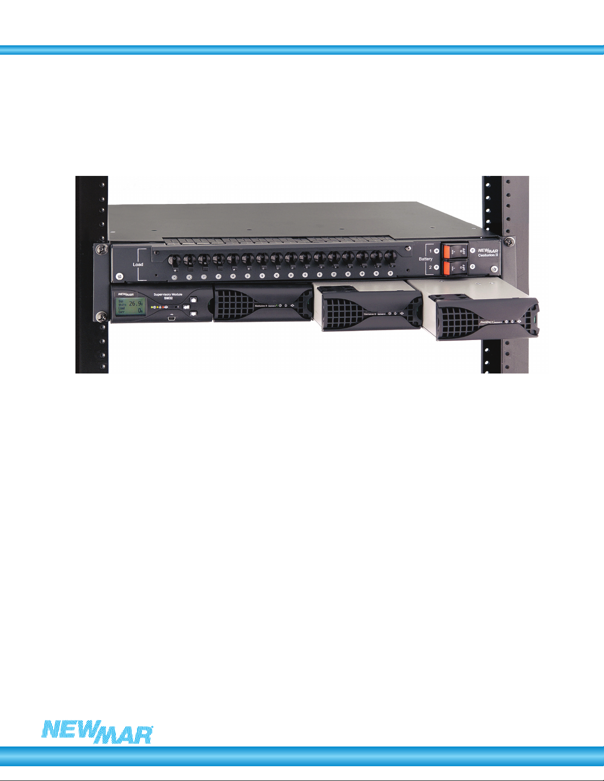
Unpacking & Installing in Frame ........................................................................................... 3
4.2
AC Cabling.............................................................................................................................. 4
4.2.1
Upstream Over-current Protection............................................................................. 5
4.3
DC Cabling.............................................................................................................................. 6
4.3.1
Terminal Block Labeling………………
.....................................................................6
4.3.2
Terminal Block Max Wire Size/Recommended Torque……………………………..6
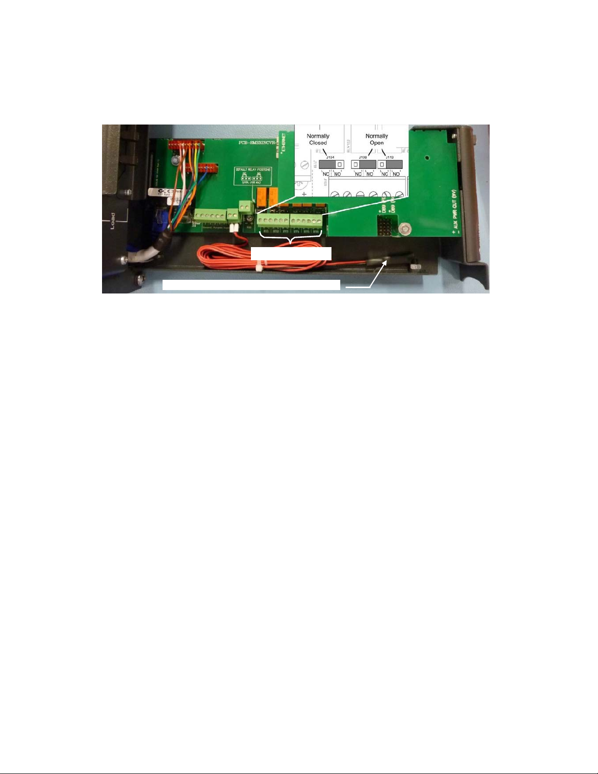
4.4 Alarm/Ancillary Cabling.......................................................................................................... 8
5
LVD Operation ......................................................................................................................10
6
Commissioning ......................................................................................................................11
7
Appendix 1 – Newmar Essential System Set – Up Parameters ....................................... 18
8
Appendix 2 – Maintenance .................................................................................................. 20
9
Appendix 3 – AC Input Transient Protection ...................................................................... 21
10
Appendix 4 – Rectifier Input Fuse Curves .......................................................................... 23
11
Appendix 5 – Installation of AC JunctionBox.......................................................................24
12
Appendix 6 – Troubleshooting .............................................................................................. 25
13
Appendix 7 – Field Replacement of Load Circuit Breakers.................................................26
14
Appendix 8 – System Wiring Diagrams............................................................................... 27
InstallationCD
You may have received a CD with your Centurion II Power System. This contains the user manuals relevant to the
System you have purchased, plus the SM3x Configuration Software. This software enables direct communication
from your computer to the SM3x via the USB port.
Note: You will require Administrator rights on your computer to install this software.
If this is the first time you have used the SM3x Configuration Software, then the installation process will guide you
through the installation of:
the USB drivers,
the Microsoft .Net Framework
the SM3x Configuration Software itself
Upon inserting the CD, open the file directory. In the root directory there is a file called Setup_sm3xconf_4.2.exe.
Double click on this and you will be guided through the installation process. Normally, you should only be required to
click “next” on all prompts.
The number “...4.2” denotes the release issue of the Configuration Software (the file you receive may be 4.3, 4.4 or
greater). If you have an earlier version installed than the number denoted there, then you can automatically update
your existing software by double-clicking on this .exe file (it will not re-install your USB drivers or the .Net
Framework).
The first time you connect your computer to a SM3x via the USB, Windows will “find new hardware”. Proceed to
install the drivers “automatically”. If, during this process, you get a message from Windows stating that the driver is
unsigned, it is not a problem. You must continue with the driver installation.

2
Newmar • PO Box 1306, Newport Beach, CA 92663
• Phone: 714-751-0488 • E-mail: techservice@newmarpower.com
1
RECEIVING INSTRUCTIONS
CAUTION: For your protection, the following information and the product manual should
be read and thoroughly understood before unpacking, installing and using the
equipment.
We present all equipment to the delivering carrier securely packed and in perfect condition.
Upon acceptance of the package from us, the delivering carrier assumes responsibility for its
safe arrival to you. Once you receive the equipment, it is your responsibility to document any
damage the carrier may have inflicted, and to file your claim promptly and accurately.
Package Inspection
Examine the shipping crate or carton for any visible damage: punctures, dents and any
other signs of possible internal damage.
Describe any damage or shortage on the receiving documents and have the carrier sign
their full name.
Equipment Inspection
Within fifteen days, open crate or carton and inspect the contents for damages. While
unpacking, be careful not to discard any equipment, parts or manuals. If any damage is
detected, call the delivering carrier to determine the appropriate action. They may require
an inspection.
Save all the shipping materials for the inspector to see!
After the inspection has been made and you have found damage, call us. We will determine
if the equipment should be returned to our plant for repair or if some other method would be
more expeditious. If it is determined that the equipment should be returned to us, ask the
delivering carrier to send the packages back at the delivering carrier’s expense.
If repair is necessary, we will invoice you for the repair so that you may submit the bill to the
delivering carrier with your claim forms.
It is your responsibility to file a claim with the delivering carrier. Failure to properly file a
claim for shipping damages may void warranty service for any physical damages later
reported for repair.
Handling
Handle the equipment with care. Do not drop or lean on front panel or connectors. Keep away
from moisture.
Identification Labels
Model numbers are clearly marked on all equipment. Please refer to these numbers in all
correspondence with Newmar.3
2
S
COPE
This manual covers essential information for the installation and commissioning of the
Centurion II DC Power System
System set-up for the rectifiers, alarms etc., are provided in separate manuals for the SM36 (C2C-
36) supervisory module and rectifiers.
All installation and maintenance must be carried out by suitably qualified personnel.
Note: The Centurion II System is available with Positive Earth (-48Vdc, -60Vdc) or Negative
Earth (+24Vdc). The installation manual covers both Positive and Negative Earth
systems. The standard system is assumed to be a Positive Earth system. Where
parameters and settings differ between systems, the Negative Earth system parameters
are specified within parenthesis i.e. ().
3
SYSTEM OVERVIEW

3
Newmar • PO Box 1306, Newport Beach, CA 92663
• Phone: 714-751-0488 • E-mail: techservice@newmarpower.com
The Centurion II DC Power System has a maximum power output of 6.0kW (+24V rated to
3.0kW @ 24V, 3.3kW @ 27V), producing a maximum current output of 125A/-48V (125A/
+27V).
The system is intended to be a complete power system in a box, so no connections need to be
made internally. All the AC, DC (Load and Battery) connections are made at the rear of the unit.
Alarm connections are accessible from the front by pulling the Supervisory Module forward.
The system is designed to be extremely simple to install and set up.
The following is a summary of the system:
-
Overall size is 483mm wide (19” standard mounting) x 88.9mm (3.5”) high (2U) x 350mm
(13.78”) deep
-
Up to 3x 37 amp (-48V or +24V) C2R-2000 or C2RX-2048 rectifiers 41.7A max (may be packaged
separately) or 3 x 18 amp (-48V) C2R-1000 rectifiers
-
SM36 supervisory module (fully integrated in the system)
-
Battery Low Voltage Disconnect fitted as standard (125A rating).
-
2x 100A Battery Circuit Breaker.
-
8x 10A, 4x 20A, 4x 30A default Load Circuit Breakers, these maybe specified as different values
(from 2A to 30A) at time of order.
-
System weight is approximately 8.4kg (18.5 lbs.) without rectifiers, and 13.2kg (29 lbs.) with
three rectifiers fitted.
-
Three sets of single phase input terminals: A-L1, B-L1, C-L1 & A-L2, B-L2, C-L2 plus Earth
are provided to allow several input wiring options: See drawing #M-C2ACOPT located in
manual bag for more information on AC wiring options .
Note: Two 3 position terminal
block links/jumpers areprovided (in manual bag)
for single high current AC source
wiring.
Note: This system is supplied with the AC and DC earths connected unless chassis DC
isolation is specified when ordering. The standard -48 VDC system output has the DC
Common inthe positive side of the circuit (+ve earth system). On +24 VDC systems,
the DC Common has thenegative side of the circuit (-ve earth system) connected to
system chassis/earth. The earth link can be removed from the system to isolate
earths. Please see section 4.2 'AC Cabling'.
4
I
NSTALLATION
4.1
Unpacking & Installing in Frame
Upon unpacking, check that the unit is not damaged, and that you have the required number of
rectifiers.
The unit flush mounts into a standard 19” mounting frame. The mounting screws should be
#12-24; however #10-32 may be used with washers. Be sure to mount the unit in the 19” frame
squarely if #10-32 screws are used.
Please note the complete system weight is 13.2kg. (29 lbs.). Ensure the 19” mounting rails are
able to withstand mounting of the system.
A 5/32" (4mm) wide slotted screwdriver has been provided to allaow ease of accessing some of
the smaller recessed DIN style terinal block screws.

4
Newmar • PO Box 1306, Newport Beach, CA 92663
• Phone: 714-751-0488 • E-mail: techservice@newmarpower.com
4.2
AC Cabling
The AC terminals are clearly marked at the rear of the system as shown in Fig 1.0 & 1.1. The
terminals can accept up to 8AWG/10mm2 cables.
Once cables are connected, ensure cable clamps are secured. Refer to appendix 5 for AC
junction box cover
removal (page 24)
The ACearth terminal earths the System chassis. The AC earth is also internally bonded to
the
System chassis by earth stud as shown in Fig 1.1. The AC earth terminal can accept
several small cables or up to a single 2 AWG cable.
DC Common (+ve) is connected to the AC earth as shown in Fig 1.1, but can be removed if
output is required to be isolated.
Note: Refer Appendix 3 for AC Input Transient Protection
Fig.1.0
AC Input Terminals
CAUTION: For 3 phase operation remove the Single Phase link fitted between the
phases.
AC Input Terminals
AC Junction Box AC Junction Box
w/CoverRemoved
Note:SeeAppendix5forinformationregardingthe AC junction box.
Shown with 3
position jumper
installed
Shown with 3
position jumper
installed
AC Input Terminal

5
Newmar • PO Box 1306, Newport Beach, CA 92663
• Phone: 714-751-0488 • E-mail: techservice@newmarpower.com
Earth
Stud
AC-DC Earth Link
(Remove link for
Isolated DC Output)
Fig.1.1 AC – DC Earth Link
4.2.1
UpstreamOver-currentProtection
There are two considerations to take into account when selecting an appropriate fuse/circuit
breaker.
-
The upstream protection should protect the downstream cable from overload situations.
-
Discrimination should be maintained with the downstream device fuses.
(i)
Cable Rating
The maximum current drawn by the DC power system is 12.5A per 2kW rectifier (6.2A for 24V
system and 48 VDC/1 kW rectifier modules), or 37.3A (18.7A for 24V system and 48 VDC/1 kW
rectifier modules) per fully populated rectifier shelf at a minimum input voltage of 175V AC and
full output power. The upstream protection device must be able to supply this load under all
conditions without tripping. Therefore, typically at least 20% headroom is allowed for the
protection device, making its minimum rating 15A/per 2kW rectifier (7.5A) or 44.8A (22.5A) for
fully populated rectifier shelf.
Note: The current carrying capacity of cables is dependent on the type of cable used. Please
check with your local supplier and local regulations for appropriate sizing.
(ii)
Discrimination
Discrimination ensures that the upstream circuit breaker or fuse does not blow if a rectifier input
fails (short circuit). Therefore it is important to ensure the upstream protection discriminates
with the internal fuse of the rectifier. The fuse used in the RM2048/24, C2R-2000, and C2RX-
2048 rectifiers is a slow-blow 15A fuse. The tripping curve for this is shown in Appendix 4 at the
rear of this manual.
A minimum circuit breaker to use for this system is a 20A, D-curve (note, a 20A C-curve breaker
will not discriminate with the rectifier fuse). Therefore, when used with the 2.5mm2 cable
supplied, a 20A, D-curve breaker should be used.

6
Newmar • PO Box 1306, Newport Beach, CA 92663
• Phone: 714-751-0488 • E-mail: techservice@newmarpower.com
Alternatively, a 32A C-curve breaker, or greater, can be used. However, AC cable provided
may have to be replaced for a larger cable1.
If a fuse is used upstream, then any BS88 or NH g style fuse, of 20A or greater rating will
discriminate.
4.3 DC Cabling
CAUTION: Use extreme care when fitting batteries & their connections. Remove all jewelry
and rings from oneself prior to commencing the installation. Always use insulated
tools when fitting batteries and take extreme care not to short terminals when
working on them.
4.3.1 Terminal Block Labeling
Note: Your Centurion II Load & Battery Terminal Blocks maybe labeled differently than shown in
photos on the following page. Some Centurion II shelves’ terminal blocks are identified by
Numbers which are the Live or Hot terminals and the words Batt. Common or Load Common
which are the Return or Ground terminals – see polarity table below.
System Voltage “Numbered’ (AKA: Live or Hot) ‘Common’ (AKA: Return or Ground)
-48 VDC - +
+24 VDC + -
4.3.2TerminalBlockMaxWireSize/RecommendedTorqueSpecification
Connection Max AWG Recommended Torque
AC Input 8 10.5 in/Lbs.
AC Earth 2 22 in/Lbs.
Loads 1 –8 8 10.5 in/Lbs.
Loads 9 - 16 10 10.5 in/Lbs.
1
NOTE:
Alargerbreakermaybeusedeventhoughintheoryitmayappearthatthe2.5mm
2
wireisnotfullyprotected.Infact
itisprotectedontwoaccounts.Firstlyitisprotectedbytherectifierinputfuse(whichisonlyashortdistanceaway).Secondly,
therectifiersarepower‐limitedontheirinput.Therefore,theycanneverbeoverloaded.Asaresult,thewirecanneverbe
over‐loadedbytherectifier–itcanonlyseefaultcurrent.Asaresult,dependingonlocalauthorities,onlyfaultcurrent
protectionmaybecateredforbytheupstreamprotectivedevice.

7
Newmar • PO Box 1306, Newport Beach, CA 92663
• Phone: 714-751-0488 • E-mail: techservice@newmarpower.com
Battery
Live
Battery
Common
CableTieSlots
LoadLive
(‐48V)
Load
Common
LoadLive
(‐48V)
Load
Common
Fig. 2 Battery & DC Output Terminals (+ve Earth System, -48V or -60V)
Battery
Live
Battery
Common
CableTieSlots
LoadLive
(+24V)
Load
Common
LoadLive
(+24V)
Load
Common
Fig 2.1 Battery & DC Output Terminals (-ve Earth System, +24V)

8
Newmar • PO Box 1306, Newport Beach, CA 92663
• Phone: 714-751-0488 • E-mail: techservice@newmarpower.com
All live DC and Common connections are made to the connectors at the rear of the unit as
shown in Fig 2 and Fig 2.1.
For 1-8 load breakers 8Awg/10mm2 terminals are used whereas for 9-16 load breakers,
10 Awg/6mm2 terminals as shown in Fig 2 and Fig 2.1.
The battery terminals shown can accept cables up to 2 Awg/35mm2.
The internal battery cabling goes directly to the circuit breaker, then via a Low Voltage
Disconnect relay and current shunt to the internal live bus. This can be seen on the wiring
diagram at the rear of this manual & in Fig 5.
Ensure cables are strain relieved by utilizing the cable tie slots provided as shown in Fig 2.
4.4 Alarm/Ancillary Cabling
Alarm and communication cables terminate directly into the terminals of the Supervisory
Module. These terminals are accessible by pulling the monitor forward to expose connections
as shown in Fig 3, Fig 3.1, Fig 3.2 & Fig 3.2a.
Fig. 3 (left): For removal, unlock SM31/32 by lifting green locking tab.
Fig. 3.1 (right): For SM35/36 removal, pull monitor forward to release the ball catch
When routing the cables, ensure they are kept away from the AC and DC power cables when
possible.
For SM31/32 relay states labelled Normally Open or Normally Closed are for their de-energized
state.
Volts – Free
Relays
SM31/32
Supervisory
Monitor
Fig. 3.2 SM31/32 Monitor Cabling

9
Newmar • PO Box 1306, Newport Beach, CA 92663
• Phone: 714-751-0488 • E-mail: techservice@newmarpower.com
Volts–FreeRelay
Battery Temperature CompensationSensor
Fig.3.2a
SM35/36 Monitor Cabling
For SM35/36Relays1‐ 6canbeusedfornormallyopenornormallyclosedstatesbyjumper
selection.TherelaystateslabelledNOorNCisfortheirde‐energizedstate.
If an alarm is programmed for the relay to be normally energized (as may be required in the
case of a low voltage alarm where loss of power will put the alarm into its active state), then be
sure to connect the remote wiring appropriately.
For full monitor functionality and operation information, refer to the appropriate monitor manual.
Temperature Sensors
Uncoil the battery temperature sensor tie wrapped to rear of shelf and place in the middle of the
middle battery string. If the lead is not long enough, ordinary 2-core copper (approx. 18
AWG/0.75mm2) wire can be used as an extension. The purpose of the battery temperature
sensor is to monitor the ambient temperature of the batteries over long periods of time and
adjust the rectifier output (float) voltage accordingly. As a result, it is not necessary to have the
temperature sensor touching the batteries. If the Battery Temperature Sensor is removed a
“battery temp fault” alarm is generated.
The “Ambient” temperature sensor (optional) can be used to monitor the temperature in another
location if required.
Connecting via Computer
For remote communications and direct computer connection to the Compact System, refer to
the SM36 Manual. These connections can be made via the mini-USB port on the front panel of
the monitor (computer connection to the SM36, USB cable included) and the Ethernet port
(SM36 web-based communications only). The Ethernet port has been extended to the rears of
the shelf via a patch cord and RJ45 coupler for installer convenience.
When a laptop/pc isconnected for the first time to the SM36, the USB drivers will have to
be
installed on the connected computer. See the SM36 manual for details.
Help files can be accessed for a field by left clicking inside the field and pressing the F1
key on the keyboard. Example shown in Fig. 4

Newmar • PO Box 1306, Newport Beach, CA 92663
• Phone: 714-751-0488 • E-mail: techservice@newmarpower.com
10
Fig. 4
Alarm Mapping to Volts-free Relays
The SM36 has three voltage-free alarm relay outputs as standard
Note that on all systems, Relay 1 is pre-configured as the “Monitor Fail” alarm. This alarm
activates if the monitor has a hardware fault or if software becomes corrupted.
All other relays can be mapped to different alarm conditions. The SM36 Manual details how
these may be changed. On the standard Centurion II Systems alarms are preconfigured as
follows:
Relay 2: Summary Non-urgent alarm
Relay 3: Summary Urgent alarm
Relay 4, 5, & 6: User configurable
As mentioned, if these mappings are not appropriate, they can be changed in the field to suit
customer requirements.
General Purpose Digital Inputs (GPIP) for external alarm contacts.
Circuit Breaker Fail Monitoring
Load circuit breakers are monitored electronically via a diode to a digital input on the SM36. The
digital input will trigger an alarm when it is pulled to the system Common (positive) rail. This
means that to operate, the load must be connected. In this way, false alarms are avoided when
no load is connected and the load circuit breaker is in the “off” position.
Note: This means that a residual voltage will be measured at the load terminal even when the
circuit breaker is turned off. This is high impedance and does not present a hazard to
the user, this is normal.
The battery circuit breakers however, use auxiliary contacts to detect tripping or whether they
are turned off. This is because when a battery breaker is tripped, there may be very little voltage
difference, making electronic fail detection problematic. Hence, if only one battery is connected,
both breakers must be “on” to clear the Battery Breaker Fail alarm.
5 LVD OPERATION
This system is configured with one Low Voltage Disconnect contactor, in the battery side of the
circuit as shown below & in the Wiring Schematic at rear of this manual.
The SM36 Supervisory Monitor unit is powered from both the rectifier side of the battery LVD
contactor and battery source. Therefore when the low voltage threshold of Battery LVD is
reached, the LVD disconnects the battery and the SM36 will lose voltage sense (as voltage

Newmar • PO Box 1306, Newport Beach, CA 92663
• Phone: 714-751-0488 • E-mail: techservice@newmarpower.com
11
sense is measuring rectifier bus voltage) but still maintains operation for system monitoring.
The Battery LVD contactor will not re-engage until the rectifier power is restored (i.e., until the
DC bus voltage is restored).
LVD adjustments/settings are all made from the SM36. See the SM36 manual for details.
The LVD contactor is a bi-stable, magnetically latched contactor. This means that failure of
power or removal of the SM36 from a live system will not cause the contactor to change state.
Load Fuse
Fail PCB
Current
Shunt
System Live Battery
Bus LVD
FIG.5
System Internal View
6 C
OMMISSIONING
Use the following set of instructions as a guide, unless different procedures are recommended
by local authorities.
Note: Refer to Appendix 1 to check important System Set-up parameters while commissioning.
Pre-check:
1.
No more building work to be carried out in site to avoid concrete and plaster dust being
ingested into rectifiers and systems.
2.
System installation is completed.
3.
Battery and load circuit breakers are turned off, and upstream AC has been turned off (i.e.,
system is completely de-powered).
4.
Rectifier modules have been fitted into their shelf positions, and pulled forward enough to
disconnect them from the system.

Newmar • PO Box 1306, Newport Beach, CA 92663
• Phone: 714-751-0488 • E-mail: techservice@newmarpower.com
12
Note: Unless chassis DC isolation is specified when ordering, this system is supplied with the
AC and DC earths connected. This system has DC Common in the Positive side of the
circuit (+ve earth system or -48 VDC). Before connecting the Batteries or Rectifiers
ensure that Earthing is correct for your application (24 VDC are normally wired for –ve
earth system or +24 VDC).
5.
Turn on AC upstream and check that voltages from phase to neutral are as expected.
Rectifier Start-up
1.
Turn the upstream AC circuits on.
a)
Confirm operation voltages between each set of Line inputs A, B, and C:
A-L1 to A-L2 = 208 or 230 volts, B-L1 to B-L2=208 or 230 volts, C-L1 to C-L2 = 208 or 230 volts
b)
Check voltages between each set of Line inputs and ground:
A-L1 to Ground = 208 or 230 volts, B-L1 to Ground = 208 or 230 volts, C-L1 to Ground = 208 or
230 volts
A-L2 to Ground = 208 or 230 volts, B-L2 to Ground = 208 or 230 volts, C-L2 to Ground = 208 or
230 volts
2.
Fully insert first rectifier, wait for the rectifier to start and its power on LED to remain green.
3.
Check the SM36 powers up, and indicates the system default float voltage (approx. 54V on
its display). If the audible alarm activates, press any SM36 button to silence it.
4.
If a different system float voltage has been specified, set this at this time using the
procedure specified in the SM36 Manual (either from the front panel or connected
computer).
5.
Fully insert the rest of the rectifiers ensuring they power up with only their green “power on”
LED illuminated.
6.
Check that the load and battery currents on the SM36 are 0 amps (+/- 1 or 2 amps).
7.
Check that all SM36 configuration settings are correct (as per customer specification) with
respect to:
-
Voltage levels
-
Alarm settings
-
Alarm mappings to the volts-free relays
(Refer to the SM36 manual for information on how to check these via the front panel or
locally connected computer).
Battery Start-up
Note: It is preferable that battery circuit breaker connections should be made when the
rectifiers are turned on and the system is “live”. This is because the system voltage
and battery voltages will be similar, thus minimizing any arcing during connection. This
also prevents high current arcing due to the charging of the rectifier output capacitors.
1.
Power up only one rectifier initially (to limit any damage if any connections are incorrect).
2.
Measure the voltage across each battery string at the terminals of the Compact System.
Ensure that the reading from the DC Common bus to the Battery Live Terminals is -48V as
per System specification.
3.
Turn on battery circuit breaker measuring the battery voltage. Ensure that the voltage
increases slightly to the system Float Voltage (typically the voltage will increase from 2 to 3V
below float voltage. At this point the batteries will be drawing some current to bring them to
a full state of charge.

Newmar • PO Box 1306, Newport Beach, CA 92663
• Phone: 714-751-0488 • E-mail: techservice@newmarpower.com
13
Load Start-up
1.
Ensure downstream load connections have been made and there are no loose/floating load
cables.
2.
Turn on load circuit breaker, ensuring that the downstream equipment is being powered up
as expected.
3.
Ensure the system float voltage on the SM36 is at the level previously noted.
4.
Ensure the load current is at a level expected (could be zero if loads downstream have not
been connected).
Note: Prior to leaving the system after it has been commissioned, ensure all AC, DC and
battery circuits are off. If it is required that the system is to be left on (to power load
equipment, ensure rectifiers are left in their powered up state, and batteries are in circuit.
This will prevent anyone leaving the batteries only powering the load (in which case the
batteries would go flat).

Newmar • PO Box 1306, Newport Beach, CA 92663
• Phone: 714-751-0488 • E-mail: techservice@newmarpower.com
14
DC System Commissioning Check List
Note that the values in the following check-boxes are for a 48V nominal system, and are for
example only. Values for a 24V system are proportionately lower.
This check-list can be altered and printed off for use as required.
DCS
YSTEM
C
OMMISSIONING
C
HECK
-L
IST
Site Name: Date:
Tests Without Batteries Connected
Measured/
Setting
Results
Check Float Voltage Meter:
V
/
Check Load Current Meter:
A
/
Alarms:
Voltage thresholds can either be checked using an external power supply, or by
adjusting the SM36 float voltage 0.1V above (or below for the low voltage alarms). It
is recommended to have the batteries disconnected.
1.
Adjust the supply/float voltage to 55.7V & observe the “High Float” alarm.
2.
Adjust the supply/float voltage to 57.7V & observe the “High Load” alarm.
3.
Adjust the supply/float voltage to 52.7V & observe the “Low Float” alarm.
4.
Adjust the supply/float voltage to 46.9V & observe the “Low Load” alarm.
High Load Volts (urgent) 57.6V
V
/
High Float Volts (non-urgent) 55.6V
V
/
Low Float Volts (non-urgent) 52.8V
V
/
Low Load Volts (urgent) 47.0V
V
/
Depending on the test load available, it may be necessary to adjust the High Load
Current alarm threshold down to suit. For example, with the 70A test load, adjust the
High Load Current threshold (use SM36 Config. software, click on the
“Alarms/(Levels)”) to 60A. Then simply apply the 70A load and observe the alarm
change state.
Once the test is complete, be sure to rest the High Load Current to its previous value
(or check with the customer for the correct value they require).
High Load Current (urgent)
A
/
Temperature alarm tests are performed by heating up (using a heat gun or other
source) and cooling down (using an aerosol can of freeze, or a tub of ice) the
temperature sensors. Note that when the Battery Condition Monitor is used, there is
one sensor per battery string. The SM36 uses the average of these temperatures as
the “Battery Temperature”. Therefore, all the sensors need to be heated / cooled at
the same time.
Battery Temperature High (urgent)
°C
/

Newmar • PO Box 1306, Newport Beach, CA 92663
• Phone: 714-751-0488 • E-mail: techservice@newmarpower.com
15
Battery Temperature Low (non-urgent)
°C
/
Room Temperature High (non-urgent)
°C
/
Room Temperature Low (non-urgent)
°C
/
When an AC Monitoring PCB is not fitted at system level (as in most cases), the AC
Fail alarm is generated from the rectifiers. The rectifiers sense if AC is present, and
extend an AC fail alarm to the SM36. Therefore, to test this alarm, simply turn off the
rectifier AC breakers. To allow the monitor to continue to read alarms there must be
DC present on the output of the system.
As this causes the rectifier output to cease, a Rectifier Fail alarm is also generated.
To generate the Urgent Rectifier Fail, turn off the required number to make this occur
(Usually set to 1, but check via the SM36 Config software for the setting (under the
“Rectifier Control” section of the “Power Module Control” tab)).
AC Fail (urgent) Urgent
/
Rectifier Fail (non-urgent) Non-urgent
/
Urgent Rectifier Fail (urgent) No. Modules:
/
To check Load MCB Open, connect a load, but with no load turned on. Then switch
the breaker to it’s off position and turn on some load (any amount will do). This will
cause the alarm to occur as the load side to the circuit will be taken to system
common voltage. Turn off the load, and then return the breaker to its ON position.
Load MCB Open (urgent)
/
The battery circuit breakers use auxiliary contacts to detect tripping or
whether they are turned off. This is because when a battery breaker is
tripped, there may be very little voltage difference, making electronic fail
detection problematic. Hence, if only one battery is connected, both breakers
must be “on” to clear the Battery Breaker Fail alarm.
To check Battery MCB open alarm, turn off the battery circuit breaker.
Battery MCB Open (urgent)
/
To check the Surge Protection Failed alarm, simply pull the MOV out. This switches
a micro-switch within the SPD unit. Once pulled, observe the alarm, and re-insert
the MOV block and observe the alarm clear. (Only available when SPD is fitted in the
system).
MOV (SPD) Fail (urgent)
/
A Rectifier Off Normal alarm is generated with the rectifier enters a state that may
degrade its performance (e.g., a single fan fail), or a state that is outside of normal
operating conditions (e.g., high temperature, or current limit).
You can observe an Off Normal alarm when the system is placed in current limit, or
you may wish to stop a fan to generate the alarm. The best way to stop a fan is to
use a small cable tie (non-metallic), and push it approximately 1cm through the
rectifier grille.
Rectifier Off Normal (e.g., fan failed) (non-urgent)
/

Newmar • PO Box 1306, Newport Beach, CA 92663
• Phone: 714-751-0488 • E-mail: techservice@newmarpower.com
16
Testswith Batteries
Set Vf to equal battery voltage
Connect battery/batteries
Check the correct Battery Capacity (Ahrs) has been entered (SM36 Config.,
“Charge” tab). This is the total capacity, so for 100Ahr string, this should be
100.
Go to SM36 Config, “Control” tab. Set the Battery Charge Current Limit to “Enabled”
(middle right of screen). Also check Battery Current Limit (BCL) is set to desired level
(usually 0.25C10, (25%)). This means that for a single 100Ahr battery, the BCL will be
25A, or if two 100Ahr batteries are connected in parallel, the BCL will be 50A.
Go to SM36 Config. “Battery Monitoring” tab. “Tick” Logging Enabled.
Set:
-
Status Log Sampling Interval to 7 days (provides a “snapshot” of the battery
state every 7 days)
-
Discharge Log Sampling Interval to 1 minute
-
Discharge Log Continuation Time to 5 minutes (this is the length of time
logging continues for after AC power is returned)
Connect load (but turn off).
Set Vf to 54.0V.
Turn on Battery Breaker/s
Check Battery current is positive if charging
/
For systems fitted with Battery Monitoring
(BCM) cards:
Go to SM36 Config., “Battery Monitoring” tab
and “tick” start scanning.
Check that the all the battery cell voltages are
approximately the same, at about 2.25V (or
13.5V for 12V monoblocs).
If any are out by a large amount, then check
the BCM sense wiring is correct
Set load to required level (e.g., 50A),
Initiate Battery Discharge Test (from SM36
Config., “Charge” tab, click “Battery Test
Enabled”)
Check operates
/
Check Battery Current is negative
(discharging)
/
Check Battery Current Meter:
A
/
After several minutes or until the battery
voltage has dropped below approx. 47V, “un-
tick” (stop) Battery Test (from SM36 Config.,
“Charge” tab). During this time the Battery
Condition Monitor (if fitted) will be logging
every minute.
Battery Current Limit (BCL)
Check that the battery recharge current is
BCL functions

Newmar • PO Box 1306, Newport Beach, CA 92663
• Phone: 714-751-0488 • E-mail: techservice@newmarpower.com
17
Limited to the Battery Current Limit level
(usually between 0.25C10, (25%))
Note: as the BCL is based on fine voltage
control of the system bus, the BCL make take
one or two minutes to “settle”, i.e., you may
observe a brief excursion of the battery
recharge current beyond the BCL setting.
%
Yes/No
Check Manual Equalise (if configured)
/
Temperature Compensation
Ensure Temperature Compensation Enabled
Yes/No
Apply heat or cold to the Battery Temperature
Sensor/s. Check the float voltage moves up or
down as expected.
Yes/No
If actual measurement is required, apply a
known heat or cold to the sensor. Allow it to
fully come to temperature, and record the
amount of voltage movement.
Temp. °C
Voltage offset:
V OK?
Yes/No
Check Alarm Relay Contacts
To generate these alarms, refer to the procedures described earlier in the
Commissioning Che ck -list.
Spare relays will not be able to be tested unless an alarm is mapped to them. As
these are tested in the factory, it is not essential to test them at time of
commissioning.
Relay 1 (Monitor Fail)
(pull out the RJ45 lead connecting the monitor
to the system rectifier shelf – this simply de-
powers the monitor)
/
Relay 2 (Summary Non-urgent)
/
Relay 3 (Summary Urgent)
/
Relay 4 (Spare)
For SM35/36 only
/
Relay 5 (Spare)
For SM35/36 only
/
Relay 6 (Spare)
For SM35/36 only
/

18
Newmar • PO Box 1306, Newport Beach, CA 92663
7
APPENDIX 1 – NEWMAR ESSENTIAL SYSTEM SET – UP PARAMETERS
The following items 1 through 5 are system settings that MUST be checked for EACH system
installed, at the time of commissioning.
WARNING: Failure to correctly follow the procedures in items 1 to 5 below may at least cause
incorrect system function, and at worst ruin your battery (without the ability to claim
battery replacement under warranty).
PRIOR to making any changes to settings, ensure that you back up the Configuration settings
that the SM36 is supplied with. To do this, go to the Setup page and click on the “Save
Variable to File” button. The filename is saved with a “.SM3x” extension.
Note that the values in the following check-boxes are for a 48V nominal system, and are for
example only. Values for a 24V system are proportionately lower.
1.
Check/Set Float Voltage
Consult battery manufacturer’s data for proper setting.
The Float voltage is for 25°C reference temperature in Newmarsystems.
SM36 Config Page: Power Module Control
2.
Set Battery Settings
Temperature Compensation
You must consult the battery manufacturer’s data to obtain the correct Slope setting.
SM36 Config Page: Charge
If you choose not to enable Temperature Compensation, then set the Rectifier Float Voltage to
that required by the battery manufacturer for the average long-term temperature you anticipate
your system to operate at.
3.
Battery Size
For the SM36 to set the correct Battery Current Limit current, it is essential that this is filled out
correctly. These figures are also used for estimating the Battery Time Remaining during a
discharge.
For Telecom applications, the 10 hour rate is usually the name-plate rating of the battery.
However, once again, check the battery manufacturer’s data sheets as some manufacturers
state the 20 hour rate (which is usually a little more “optimistic”).
The second rate is required specifically for the time-remaining algorithm. A 4 hour rate is
usually a good one to use. This information is available from the battery manufacturer’s data
sheet.

19
Newmar • PO Box 1306, Newport Beach, CA 92663
SM36 Config Page: Charge
Note – you need to change both the 10 hour and 4 hour rates at the same time. The rates need
to be reasonably accurate (in terms of the proportion of 4 hour to 10 hour rates), otherwise the
SM36 may not accept the settings.
4.
Battery Current Limit
The Battery Current Limit is set as a percentage of the 10 hour rate entered in step 3.
SM36 Config Page: Control
Newmar recommends that you set this value at the highest rate possible to ensure the battery is
recharged as fast as possible (this could be as high as 30%, depending on the manufacturer).
However, especially in large systems, this may be more limited by the number of rectifiers
available, rather than this particular setting. For telco settings, this is often set to 10% (or
0.1C10, so for a 100Ahr battery, the current limit is 10A). This is more typical of a design
parameter than the need for the setting to be at this level. So a setting higher than this level
should be considered to enable the fastest recharge possible. However, consult the battery
manufacturer data to find the maximum value.
5.
Low Voltage Disconnect Settings
SM36 Config Page: Alarms (Levels)
This is usually a customer generated setting. Normally, the longer the discharge, the higher the
end voltage. So, for a discharge of <1hr, this may be 1.75Vpc (42.0V for a “48V” battery), or for
an 8 hour discharge, it may be 1.85Vpc (44.4V for a “48V” battery).
Note that if only one LVD is fitted, then the other thresholds (of LVD2 & LVD3) are normally set
well outside of possible tripping voltages. Although not essential, and those LVDs will not be
enabled anyway, it serves to avoid any confusion over which LVD signal is actually being used.
Other manuals for Centurion II
1
This manual suits for next models
1
Table of contents
Other NewMar Power Supply manuals

NewMar
NewMar Centurion CR48-10 User manual

NewMar
NewMar PM-24-80 User manual

NewMar
NewMar SPS 12-20 User manual

NewMar
NewMar C2R-2000 User manual

NewMar
NewMar Centurion III C3RS-48-124 User manual

NewMar
NewMar Phase Three PT-CE Series User manual

NewMar
NewMar RM2048HE User manual

NewMar
NewMar STARTGUARD NS-12-20 User manual

NewMar
NewMar Centurion II User manual

NewMar
NewMar POWER-PAC User manual