manuals.online logo
Brands
  1. Home
  2. •
  3. Brands
  4. •
  5. NewMar
  6. •
  7. Power Supply
  8. •
  9. NewMar Centurion CR48-10 User manual

NewMar Centurion CR48-10 User manual

P.O. Box 1306, Newport Beach, California 92663 • Phone: 714-751-0488 • Fax: 714-957-1621 • E-Mail: [email protected]
www.newmartelecom.com
1
Centurion Rectifier System
Models:
CR48-10: 48 Volt, 10 Amp Rectifier
CR24-20: 24 Volt, 20 Amp Rectifier
CRS: Rectifier Shelf (3 rectifier bay controller)
INSTALLATION / OPERATION MANUAL
Section
Overview I
Shelf Installation II
A) Mounting
B) AC Input
C) DC Output/Battery Connection Points
Rectifier Installation/Operation III
A) Installation
B) Rectifier Module Output Indications
Shelf Controller And Rectifier Operation/Adjustment IV
A) Start-Up
B) Output Voltage Adjustment
C) Controller Indications
Alarm Contacts V
A) Minor
B) Major/Output OK
C) Alarm Connector Wire Assembly
Battery Charging VI
Removing and Installing the Controller Assembly VII
System Component Options VIII
A) Power Function Manager, Model PFM-400
B) Circuit Breaker Distribution Panels
Specifications IX
Dimensional Drawings X
M-CR-CRS
As of Nov. 2006
P.O. Box 1306, Newport Beach, California 92663 • Phone: 714-751-0488 • Fax: 714-957-1621 • E-Mail: [email protected]
www.newmartelecom.com
2
I) Overview
The Centurion Rectifier System comprises a low profile 3.5" (2 RU)
shelf which accommodates up to three 550 watt, -48 or +24 volt hot-
swap rectifiers and a system controller/monitor module. The system
is scalable/adaptable for N, N+1 or N+2 configurations.
Front panel test points and single point voltage adjustment pot are
provided for fine-tuning output to the requirements of sensitive loads
or float charge requirements.
Alarm contacts enable remote alarms for the rectifier system.
Front panel OK/FAIL LED's allow monitoring status of each rectifier
individually.
The Centurion system is engineered for compatibility with
NEWMAR’s Power Function Manager (PFM 400) and circuit breaker
distribution panel (DST 20/10). See section VIII, optional system
components.
II) Shelf Installation
A) Mounting
Two sets of mounting ears are provided for 19" and 23" rack
mounting. Ear attachments are in the 6” forward mounting position
and at the four corners for four point cabinet mounting (contact
Newmar for additional mounting ears.) Use the six #6-32 x 1/4" pan
head mounting screws and lock washers to secure the ears.
Note: Flush mounting is only recommended with rear support or
four point cabinet mounting.
The Centurion Rectifiers are front-to-back forced-air cooled,
therefore no empty rack positions are necessary either above
or below the unit to maintain proper operating temperature.
Other rack components may be installed above or below rectifier
shelf. Maintain at least 6" in front of and behind shelf to allow air
circulation.
B) AC Input
The Centurion Shelf/Rectifiers operates from 90-264 VAC, 47-63
Hz input. The rectifier shelf is designed for hard wiring however a
power cord can be fitted to the shelf if desired.
AC Input Wiring Chart:
Input Recommended Recommended
AC Input AC Input
Wire Size Circuit Size
115VAC 12AWG 25Amp
230VAC 14AWG 15Amp
To access the AC wiring compartment, loosen the two screws
securing the compartment cover as shown figure 1:
AC Wiring Compartment
Two AC cable entry points are provided. Feed the AC cable thru
the strain relief and then attach AC wires to the input terminal
block (TB1) as shown in figure 1. For line to neutral sources, connect
Hot/Line to “AC/L1” & Neutral to “ACC/L2”. A chassis mounted 10-
32 stud is provided for earth grounding.
CAUTION (230V AC applications only): 230V AC sources should be
protected by a double pole circuit breaker.
After wiring is completed securely tighten the two cable strain relief
screws and secure cable entry screws.
C) DC Output/Battery Connection Points
Note: Refer to the CRS Rear Panel Diagram, figure 2 below for
wiring DC output.
Minimum Output Wire Size
24 Volt (60 Amps) 6 AWG • 48 Volt (30 Amps) 10 AWG
Centurion Shelf Rear Panel Diagram
III) Rectifier Installation/Operation
A) Installation
The Centurion Shelf is voltage specific, 24 or 48 volt and accepts
either model CR 48-10 (-48 VDC) or CR 24-20 (+24 VDC) Rectifier
Modules respectively. The modules are keyed so that a 24V module
cannot be inserted into a 48V shelf, and visa versa. The system is
designed for module installation while the shelf is "hot", therefore the
modules may be removed or inserted while AC is being applied to
the shelf and loads are being powered. CAUTION: Ensure that the
power switch on the front panel of the rectifier is in the OFF position
prior to inserting or removing the module.
Slide the rectifier into the open RECTIFIER A position and secure it
using the front panel captive retaining screws. Two blank panels for
covering unused bays are factory installed in the RECTIFIER B and C
positions and are easily removed for installing additional rectifiers
These should be left in place in any unused bay(s) to optimize
proper air flow from the fans through the shelf.
B) Rectifier Module Output Indications
This indicator will glow green whenever the rectifier module is
producing normal operating voltage. In the event of failure or the
inserted power module’s power switch is in the off position, the LED
will glow orange.
IV) Shelf Controller & Rectifier Operation/Adjustment
A) Start-up
1) Apply recommended AC voltage to the shelf AC input terminal
block.
2) Turn the on/off power switch located on each installed rectifier to
the on position.
3) Verify each installed rectifier’s “Output Power”
LED is illuminated green.
4) Verify the “Output OK” green LED on the
controller is illuminated.
AC Wiring
Compartment
Figure 1
Figure 2
P.O. Box 1306, Newport Beach, California 92663 • Phone: 714-751-0488 • Fax: 714-957-1621 • E-Mail: [email protected]
www.newmartelecom.com
3
B) Output Voltage Adjustment
The factory output voltage settings and user adjustment range are
as follows:
Factory Setting Adjustment Range
CRS, 48V: 54.4 VDC 50-58 VDC
CRS, 24V: 27.2 VDC 25-29.4 VDC
Controller front panel test points are provided for calibrating output
voltage with an external voltmeter. Adjustment is made at the
controller front panel potentiometer.
Using a digital voltmeter, front panel test points and voltage
adjustment potentiometer set the rectifiers shelf output to
the recommended float voltage as defined from the battery
manufacturer.
Note: Contact Newmar if unable to perform the above procedure.
C) Controller Indications
Output OK
Indicates DC output power is available for charging. Extinguished
LED indicates excessively low or no output voltage.
Major Alarm
Indicates DC output voltage has dropped to a level no longer
providing charging current to batteries.
Minor Alarm
Indicates loss of DC voltage and/or one or more rectifier modules
have failed.
Battery Over Temp
When the optional Temperature Probe has been connected to the
CRS this LED will illuminate if the battery temperature has reached
or exceeded 50 degrees Celsius and will reduce output voltage in
order to prevent damage to the batteries.
V) Alarm Contacts
Alarm Connections
A) Minor Alarm form-C contacts are provided at J1 pins 1 (com),
2 (N/O) and 3 (N/C)
J1-1 and J1-2 will short on FAIL
J1-1 and J1-3 will open on FAIL
B) Major Alarm and Output OK contacts are provided at J1 pin 6
(Output Status COM), pin 7 (Major Alarm N/O) and pin 8 (Output
OK N/C)
J1-6 and J1-7 will short on low or no Bus voltage
J1-6 and J1-8 will short when output is providing the correct voltage
(Note: Major Alarm and Output OK ‘com’ connections are the same)
C) Alarm Connector Wire Assembly
J1 alarm connections for mating wire assembly harness with 9 pin
D sub connector Part No. 873-4625-0
Color code:
Pin Wire Color Pin Wire Color Pin Wire Color
J1-1 Brown J1-4 Yellow J1-7 Violet
J1-2 Red J1-5 Green J1-8 Gray
J1-3 Orange J1-6 Blue J1-9 White
VI) Battery Charging
Standard Float Charging
The Centurion system is designed to simultaneously
maintain back-up batteries and supply the system
load, up to the power level of the inserted modules.
Battery float voltage (output voltage) of each
system is as listed in (section IX) "specifications". Float voltage
adjustment can be accomplished as specified in section IVB.
Automatic Temperature Compensation Option via use of a
temperature compensation sensor, Model TP-TEMP (445-4129-0)
output voltage to batteries will automatically be adjusted based on
sensed temperatures as listed in table below.
CR24-20: -0.06V/°C
CR48-10: -0.12V/°C
The temperature probe installs at the rear of the shelf in the port
labeled J3, and the sensor should be attached to the battery.
3 Stage Charging Option:
The system can also be configured to cycle through a 3 stage
charging regime every time ac power is interrupted; this will result
in an absorption charge of 28.0 or 56.0 volts for up to 8 hours.
Contact Newmar for information.
VII) Removing and Installing the Controller Assembly
Controller assembly is located on the right side of the CRS assembly
and can be removed while system is operating.
To remove controller assembly, remove the #6 screw securing it
to the shelf chassis. Pull controller out approximately 2" until the
ribbon cable connector is accessible. Remove ribbon cable from P2
by grabbing the connector firmly and pulling it away from the PCB.
(Caution: Do not pull controller assembly out past the ribbon cable
connector until the ribbon connector has been removed from the
PCB.) Hold the ribbon connector away from the controller assembly
and continue to pull the controller out of the shelf assembly.
To install controller assembly, hold the ribbon cable assembly away
from the controller slot and align backing plate of controller to the
controller guides located inside shelf. Slide controller into shelf until
ribbon cable connector is close enough to reinstall into the P2 PCB
connector. Reinstall ribbon cable and continue to slide controller
in until front panel is flush with shelf chassis. Reinstall #6 screw to
secure controller.
VIII) System Component Options
A) Power Function Manager, Model PFM-400
This 2RU rack mount device wires to the output hot of the Centurion
system and provides the following functions:
1. Digital amperage and voltage read outs
2. Summary alarm contacts
3. 400 amp low voltage disconnect
4. 5 circuit breaker distribution
For details go to www.newmartelecom.com and select Power
Function Manager.
B) Circuit Breaker Distribution Panels
Distribution panels can be added to a Centurion system, with or
without using the PFM-400 above. Two models are available:
DST-20 – Accommodates 20 plug in circuit breakers, and can be
configured for dual or single input bus.
DST-10 – Accommodates 10 plug in circuit breakers in a single
input bus. For details go to www.newmartelecom.com and select
Distribution Panels.
For multiple loads a rack mount return Bus Bar is recommended.
Model BBA-800
P.O. Box 1306, Newport Beach, California 92663 • Phone: 714-751-0488 • Fax: 714-957-1621 • E-Mail: [email protected]
www.newmartelecom.com
4
IX) Specifications
Centurion Rectifiers
Input Voltage/Frequency: 90-264 VAC* / 47-63 Hz.
Input Amperage: 6 amps @ 115V and full load, 3
amps @ 230V and full load
Power Factor: .96-.99
Output Voltage/Amperage*:
CR48-10: -54.4 VDC, 10 amps continuous
CR24-20: +27.2 VDC, 20 amps continuous
* 100 % output power available from 105 VAC to 264
VAC; Derate output linearly from 100% @ 105 VAC to
80 % @ 90 VAC
Line/Load
Regulation: +/- 2 %
Ripple: CR24-20: 1% PK-PK
CR48-10: 1% PK-PK
Protection: Over-voltage, current limiting, over-
temperature, input and output fuses.
Fan Operation: Continuous air flow front to rear.
Indicators/Controls:
• Output power indicators LED
• Power switch
Operating Temperature: -10°C to +60°C; 100 % load
from 0°C to +50°C; Derate linearly to 80% load from
+50°C to +60°C and 0°C to -10°C.
Weight: 6.0 lbs.
Safety:
• EN55022 Class A
• UL 1950
• CE mark
Centurion Rectifier Shelf
Model CRS
Input: 115/230 VAC nominal
Capacity:
Up to Three Rectifiers, CR24-20 or CR48-10
Alarms/Indicators/Controls:
• Output failure contacts; Form A, Form B,
Form C, Contact rating: 1 Amp Max.
• Front panel LED indications: Minor Alarm,
Major Alarm, Output OK, Battery Over Temp
• Front panel voltage test points and adjustment
Adjustment Range: 24V: 25-29.4V, 48V: 50-59V
Battery Drain (with no AC input): <200 mA 3 rectifiers
and controller
Mounting: 19" or 23" rack
Dimensions: Refer to Dimensional Drawings
Weight: 10 lbs.
Safety: UL 1950 compliant
Rectifier
A
Rectifier
B
Rectifier
C
X) Dimensional Drawings

This manual suits for next models

1

Other NewMar Power Supply manuals

NewMar MDP-25 User manual

NewMar

NewMar MDP-25 User manual

NewMar SPS 12-20 User manual

NewMar

NewMar SPS 12-20 User manual

NewMar Centurion II User manual

NewMar

NewMar Centurion II User manual

NewMar power-pac User manual

NewMar

NewMar power-pac User manual

NewMar Centurion II User manual

NewMar

NewMar Centurion II User manual

NewMar EP 12-10 User manual

NewMar

NewMar EP 12-10 User manual

NewMar Commander II Series User manual

NewMar

NewMar Commander II Series User manual

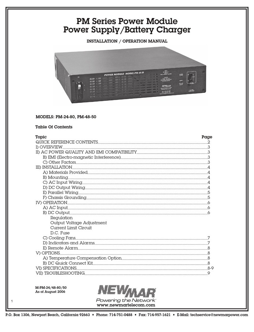
NewMar PM-12-40A PM Series User manual

NewMar

NewMar PM-12-40A PM Series User manual

NewMar PM-24-80 User manual

NewMar

NewMar PM-24-80 User manual

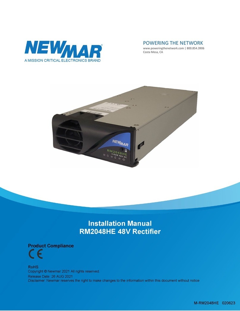
NewMar RM2048HE User manual

NewMar

NewMar RM2048HE User manual

NewMar PM-12-40 User manual

NewMar

NewMar PM-12-40 User manual

NewMar POWER-PAC User manual

NewMar

NewMar POWER-PAC User manual

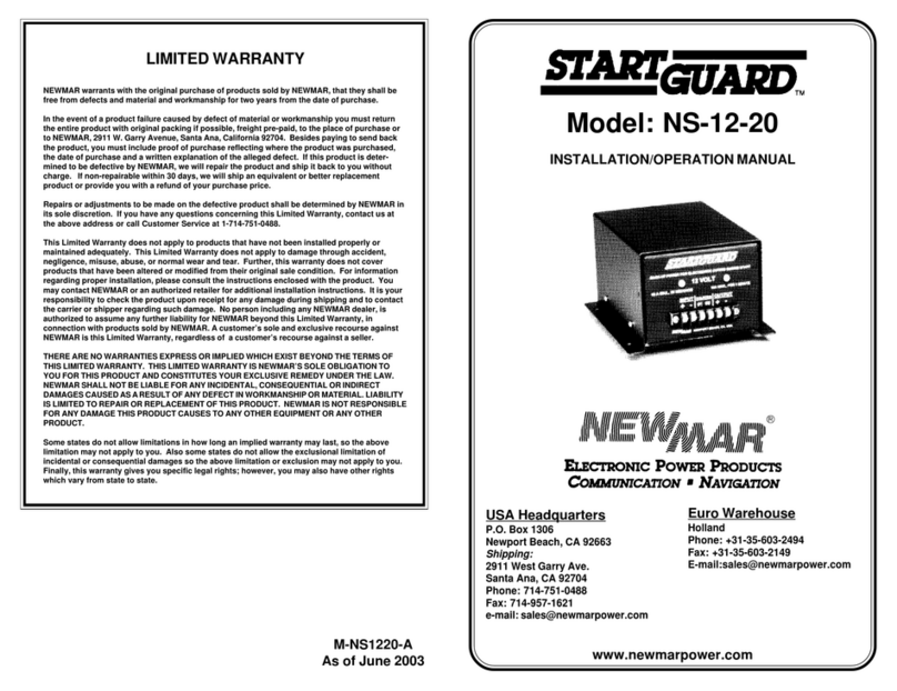
NewMar STARTGUARD NS-12-20 User manual

NewMar

NewMar STARTGUARD NS-12-20 User manual

NewMar Centurion III C3RS-48-124 User manual

NewMar

NewMar Centurion III C3RS-48-124 User manual

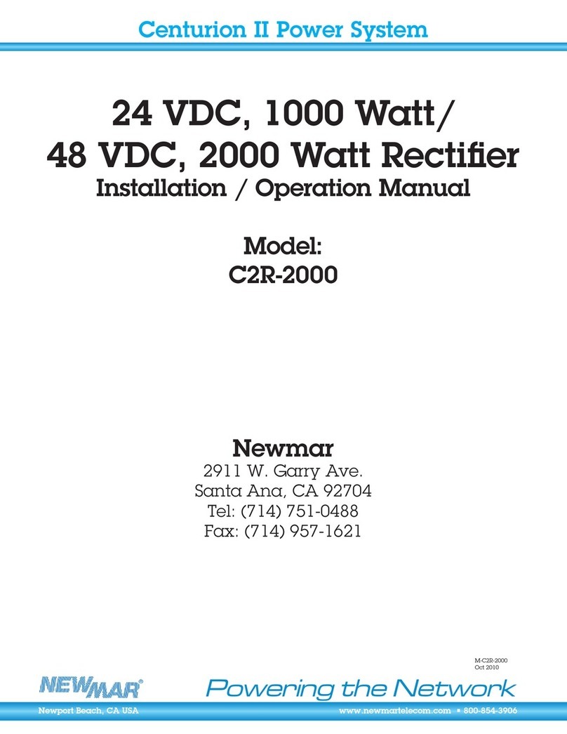
NewMar C2R-2000 User manual

NewMar

NewMar C2R-2000 User manual

NewMar PT-20CE User manual

NewMar

NewMar PT-20CE User manual

NewMar Phase Three PT-CE Series User manual

NewMar

NewMar Phase Three PT-CE Series User manual

Popular Power Supply manuals by other brands

KEPCO BOP 10-100GL quick start guide

KEPCO

KEPCO BOP 10-100GL quick start guide

KEPCO PAT 72-0. instruction manual

KEPCO

KEPCO PAT 72-0. instruction manual

B+K precision 1715A instruction manual

B+K precision

B+K precision 1715A instruction manual

Meanwell NDR-240 Series installation manual

Meanwell

Meanwell NDR-240 Series installation manual

C.P. Electronics DA-SL-PSU Product guide

C.P. Electronics

C.P. Electronics DA-SL-PSU Product guide

I-Tech IT6512D user manual

I-Tech

I-Tech IT6512D user manual

Delta CliQ II DRP024V060W1N Series Technical data sheet

Delta

Delta CliQ II DRP024V060W1N Series Technical data sheet

Fire Power FP-80 operating manual

Fire Power

Fire Power FP-80 operating manual

B+K precision 1601 instruction manual

B+K precision

B+K precision 1601 instruction manual

Isotech IPS 3303D instruction manual

Isotech

Isotech IPS 3303D instruction manual

Rocket Fish RF-700WPS user guide

Rocket Fish

Rocket Fish RF-700WPS user guide

I-Tech IT6720 user guide

I-Tech

I-Tech IT6720 user guide

Delta LOYTEC LPOW-2415A installation instructions

Delta

Delta LOYTEC LPOW-2415A installation instructions

Delta PMT2 150 W Series Technical data sheet

Delta

Delta PMT2 150 W Series Technical data sheet

OEM Tools 24454 Operating instructions and parts manual

OEM Tools

OEM Tools 24454 Operating instructions and parts manual

Axio MET AX-3020L instruction manual

Axio MET

Axio MET AX-3020L instruction manual

Lamarche TPSD Installation and operation manual

Lamarche

Lamarche TPSD Installation and operation manual

Tripp Lite Alternative Power Source owner's manual

Tripp Lite

Tripp Lite Alternative Power Source owner's manual

manuals.online logo
manuals.online logoBrands
  • About & Mission
  • Contact us
  • Privacy Policy
  • Terms and Conditions

Copyright 2025 Manuals.Online. All Rights Reserved.