Newport Brass I-540 User manual

THERMOSTATIC VALVE AND TRIM
INSTALLATION INSTRUCTIONS
MODEL NO. 1-540
Congratulations on the purchase
of this Newport Brass product,
an excellent choice that will give you
years of quality service and enhance
the look and style of your home.

General Characteristics
In case of instantaneous heaters, hot water flow has to at least meet flow required by
heater and maintain burning. (Specified by heater manufacturer)
Operating Specifications
Hot water supply temperature:
Maximum: Reference manufacturing specification
Minimum: 150°F(40°F higher than maximum required mixed temperature.)
Minimum difference between hot and mixed temperature is: 50°F
Operating Pressure:
Maximum: 70 PSI
Minimum: 20 PSI
Operating pressure (on hot and cold line) should be kept as balanced as possible in order
to assure maximum efficiency.
When the pressure is greater than 70 PSI, a pressure reducer is required. To be fitted
before valve.
T
echnical Data
The temperature control knob is graduated from 75°F to 120°F with auto stop at 100° to
avoid scalding.
Temperature limit setting of less than 120°F
Fit a stop valve/volume control between thermo valve outlet and end devise(s).
Plumbing Recommendations
• An independent water supply for both hot and cold is required. Do not pipe off ring
main.
• Large runs of pipe work will cause frictional loss of pressure.
• The recommended main water supply piping to valve shall be 3/4” min...
• If more than one valve is installed, the recommended main water supply piping to valve
shall be 1” minimum, reducing to 3/4” within 24” of each valve.
(Ensure adequate supply from both hot and cold water can be maintained.)
Water Bye-Laws
The mixing valve should be installed in compliance with the water bye laws. For further
details refer to the latest copy of bye laws guide or your local water authority.
NWP-1-540
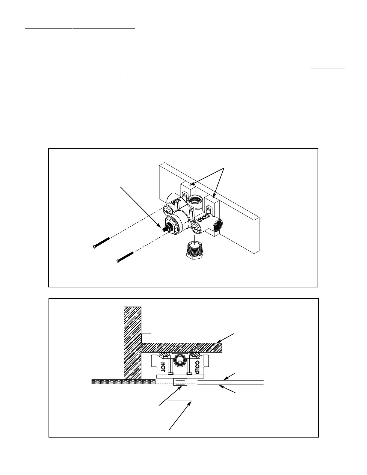
I. Rough in Valve Installation
Note: Use Teflon tape or equivalent to seal all threaded port joints.
1. Do not remove mud cover from valve before locating mounting surface depth in the wall.
2. Do not turn the cartridge stem - temperature settings are pre-calibrated at the factory.
3. Install plug into one of the two outlet ports. Note: For proper valve operation only one
outlet port may be used.
4. Mount valve to cross support using shims and screws (not included).Valve shall be perpen-
dicular and fixed firmly to cross support to achieve proper trim attachment.
5. Place the cross support with valve between wall studs.The min.../max. valve exposure tem-
plate on the mud cover and vertical height desired within tub/shower enclosure determines
the exact cross support placement.Attach cross support to wall studs.
Plug
Shim
Fig. 1
Cartridge
stem
DO NOT TURN
Maximum exposure
Minimum exposure
Finished wall
Mud cover
Mud cover
template
Wall stud
Cross support
Fig. 2
NWP-1-540

II. Connecting Water Supply
1. Thoroughly flush supply lines to remove any debris, metallic shavings, flux, etc.
2. Shut off water supply to valve.
3. Hot and cold water supplies MUST be connected to designated sides for proper operation
of valve.
4. If solder/brazing the fitting connections, pre-assembly hot & cold adapter fittings to copper
piping. Using Teflon tape or equivalent to attach adapter to appropriate inlet port.
Important: All excessive heat shall be a minimum of 4” from valve.
5. Connect outlet pipe to stop valve/volume control (not included), and from stop valve pipe
to various end device(s).
6.Turn on water supply to valve and check for leaks.
Hot water
supply
Cold water
supply
Outlet pipe
for shower
connection
4” min.
Cartridge stem
(DO NOT TURN)
Fig. 3
NWP-1-540

III. Installing Trim & Temperature Setting
1. Remove and disgard mud cover and screws.
2. Slide sleeve over valve body with grooved notch to topside.
3. Slide cover plate with gasket over sleeve and attach with decorative screws provided (see
Fig. 4).
4. Orient and position limit stop as shown below (see Fig. 5).
5. Open shut-off valve and verify water temperature at outlet device by using a thermometer.
NOTE:The safe and factory set temperature is 100°F. If the temperature needs to be adjust-
ed follow step 6, otherwise skip to step 7.
6. Rotate cartridge stem to adjust temperature:
(clockwise = colder or counterclockwise = hotter)
7. Place bonnet onto cartridge stem with red button (100°F) positioned straight up and inline
with notch on the sleeve (see Fig. 6).
8. Secure bonnet in place with long flat head screw.
9. Place decorative handle onto stem and secure with setscrew.
Sleeve
Coverplate
Valve
Fig. 4
Stop ring
Cartridge
stem
Fig. 5 Fig. 6
Bonnet
Handle
NWP-1-540

IV
.Maintenance and T
roubleshooting
The thermostatic valve has various screens that filter debris and unwanted particles that may
damage the valves' cartridge and operation.Though years of use these screens may build up
with impurities and limescale, restricting the flow of water through the cartridge and or
check valves.The following steps describe removal and cleaning procedure.
Cartridge(Reference Fig. 7)
1. Carefully remove the handle, bonnet, stop ring, cover plate and sleeve.
2. Shut off the water to cartridge by tightening center screw on each check valve, 7 turns max.
3. Unscrew the cartridge using 1-3/16” or adjustable wrench; gently remove cartridge from
housing.
4. Clean the screens by rinsing the cartridge under running water. If necessary, soak in a 50/50
mix of white vinegar and water to remove limescale.
5.Wipe cartridge and housing with wet cloth and apply a thin film of non-petroleum grease to
o-rings. Do not use Vaseline.
6. Carefully install cartridge into housing and tighten to 10 ft-lbs.
7. Fully open check valves and inspect for leaks.
8. Check operation and flow. If improved, proceed to step 9, otherwise see checkvalve section
below.
9. Reinstall trim and set temperature per section III.
O-rings Screens
Fig. 7
Sleeve
Coverplate
Stop ring
Bonnet
Handle
Check
valve
Cartridge
NWP-1-540

Check valve(Reference Fig. 8)
1.Turn water supply to valve inlets off.
2.Tighten center screw on check valve inward until it clears bottom on check valve slot.
3. Unscrew check valve with large bladed screwdriver.
4. Remove check valve and clean per step 4 and 5 above.
5. Replace valve back into housing, unscrew center and re-close to 7 turns max.
6.Turn on water supply to valve inlets.
7. Fully open the check valve screws and inspect for leaks.
8. Reinstall trim and set temperature per section III.
Filter
O-ring
Fig. 8
Check valve
NWP-1-540

(949)417-5207
NWP-1-540 Santa Ana, Ca. 92705 11/06/2002
www.brasstech.com
Newport Brass Product Care
Newport Brass faucets and bath fittings are made of solid brass and are of the finest quality. To maintain
the finish on these items, please:
- Do not use any abrasive cleaners, detergents, brass or silver polish which will scratch the surface.
- Clean with a soft damp cloth.
Applying a coating of a non-abrasive liquid wax to the clean surface of the product will keep it looking
beautiful. Brass ProTech, a product of Brasstech, Inc., can be used on all types of decorative painted and
plated finishes.
Simply apply Brass ProTech with a soft cloth and let it dry. Then remove by rubbing gently with a soft dry
cloth. Brass ProTech contains no harsh abrasives.
We highly recommend using Brass ProTech on items finished in Satin Nickel (15S), Polished Nickel (15),
Polished Silver (25) and Satin Silver (25S).
Do not allow soap scum or minerals in water to build up on the surface finish of your faucets or bath fit-
tings (including toothpaste). These will gradually eat into any finish and diminish the beauty of your
Newport Brass products.
Warranty
Newport Brass products are warranted to the original purchaser for a period of 10 years in all finishes
except as follows: Forever Brass (01) P.V.D., Satin Bronze (10) P.V.D., Polished Chrome (26), Stainless Steel
(20) P.V.D., Oil Rubbed Bronze (10B), and powder-coat colors have a lifetime warranty. Uncoated finishes
such as: Uncoated Brass (03N), Weathered Brass (03W) and Weathered Copper (08W) have no finish
warranty.
The warranty period starts from the date of shipment to the original purchaser. Kitchen, bath or lavato-
ry drains of all types, due to abuse to which they may be subjected, are warranted as follows: powder-coat-
ed colors, Polished Chrome (26), Satin Chrome (26D), Oil Rubbed Bronze (10B), Forever Brass (01) or
Stainless Steel (20) - 1 year. In all other finishes - no warranty on the finish for these products.
Ceramic disc valves (lavatory, tub/shower, and roman tub valves) have a lifetime warranty. Other valve
types (balance pressure, thermostatic, etc.) are warranted for one year from the date of purchase on
mechanical operations.
Product problems attributable to abuse, misuse, improper installation, hard water, maintenance or acci-
dental damage are not covered by this warranty. No repairs or replacements will be made under such cir-
cumstances except at customer's expense. Liability under all warranties expressed or implied is limited
to replacement of non-conforming goods only.
Flush pipes prior to installation
Solder and other debris may damage ceramic discs. Cartridges are factory set at 14-16 lbs. torque.
Table of contents
Other Newport Brass Control Unit manuals


Popular Control Unit manuals by other brands


Transmitter Solutions
Transmitter Solutions RCMMOD manual

Sparkfun Electronics
Sparkfun Electronics Qwiic Shield manual

SSS Siedle
SSS Siedle BIM 650-02 Product information

Cornelius
Cornelius UF-1 Portion Control Operation and Programming Instructions

ABB
ABB ACH550 series quick start guide

Zamel
Zamel Supla SBW-01 manual