NewTom 5G User manual
NewTom 5G – Installation Manual
0051
97070025
Rev. 2
28.10.2016
EN

NOTES
This document is provided as a consultation manual intended for the device users.
CEFLA s.c. follows a policy based on the constant development and update of the product. For this reason, it
reserves the right to change the content of this manual without prior notice.
This document can not be modified, copied, reproduced, distributed, saved on magnetic or optical supports,
or published on websites and other on-line services, in full or in part, without the prior written authorisation of
CEFLA s.c.
The original version of this manual is in english.
EWTOM™ 5G is a trademark of CEFLA s.c.
All other products and trade names mentioned in this document are registered marks of the relevant
manufacturers.
INFORMATIVE NOTE OF THE MANUFACTURER ON THE ME ICAL EVICES
The medical device referred to in this manual consists of a scanner and a control, display and calculation unit
(Main Workstation). Such device, as delivered and configured by the production and assistance technical
personnel, is an X-ray device compliant with the safety requirements set forth by the Italian Legislative
Decree of 19 September 1994, no. 626 implementing Directives 89/391/EEC, 89/654/EEC, 89/655/EEC,
89/656/EEC, 90/269/EEC, 90/270/EEC, 90/394/EEC and 90/679/EEC concerning the improvement of the
health and safety of workers in the workplace, and with the essential requirements set forth by the Italian
Legislative Decree 24 February 1997, no. 46 implementing Directive 93/42/EEC as amended, on the medical
devices.
The medical device referred to in this manual is an X-ray device compliant with Directive 2011/65/EU on the
restriction of the use of certain hazardous substances in electrical and electronic equipment.
Any tampering with, modification, updating or other change both of hardware1 and software2 of the device as
supplied and installed by the company (and in the conditions specified in the attached documentation) may
partially or totally compromise the device expected operation. This may also alter the safety features with
consequent hazard increase for patients, operators and surrounding environment.
For this reason, should the user need to modify the device, he/she must request a written authorisation by
CEFLA s.c.
Failure to comply with what is specified in this informative note will null and void the device warranty and the
civil and/or penal responsibility for any consequent damage and/or accident and/or worsening of the patient,
operator or other people health (including the surrounding environment) will be borne by the person who
tampered with the device or his/her legal representative.
1
Adding of a new memory expansion, a new hardware on the onne tion bus, a printer, the repla ement
of the graphi display interfa e represents an important modifi ation.
2
In luding the operative system and the appli ations already installed upon medi al devi e delivery.
Automati updates of the operative system, hanges to network onne tion parameters, modifi ation
and/or addition and/or removal of interfa e software with hardware (devi e driver) and/or servi es (e.g.
file and printer sharing servi e) and/or appli ations represent an important modifi ation.

Table of Contents
1 UNPACKING AND MOVING THE EQUIPMENT..........................................................1-1
1.1 Scanner Inspection And Unpacking Instructions.............................................................1-1
1.2 Moving The Equipment.........................................................................................1-10
1. Patient Table Inspection And Unpacking Instructions.....................................................1-12
2 MOUNTING AND CONNECTING THE EQUIPMENT.....................................................2-1
2.1 Lasers Setup...................................................................................................... 2-1
2.2 Mounting The Equipment....................................................................................... 2-1
2. Connecting The Equipment.....................................................................................2-7
2.3.1 Connecting The Electric Distribution...................................................................2-7
2.3.2 Connecting The Console Workstation..................................................................2-7
2.3.3 Connecting The External Emergency utton..........................................................2-7
2.3.4 Connecting The Ready State Switch....................................................................2-7
2.3.5 Connecting The X-ray Emission Switch.................................................................2-7
2.3.6 Connecting The External Door Switch..................................................................2-7
2.4 Testing The Equipment.......................................................................................... 2-7
2.5 Device Calibration...............................................................................................2-8
2.6 Finish Touches.................................................................................................... 2-8

1 Unpacking and moving the equipment
1 Unpacking and mo ing the equipment
1.1 Scanner inspection and unpacking instructions
Thoroughly inspect the exterior of the crates for damages which might have occurred during shipment.
Report any damage to delivering carrier and follow their instructions.
Each crate is equipped with a tilt watch indicator that turns from white to red if the package has tilted during
shipment. Check the indicator before opening the crates.
WARNING:
During the process of unpacking, dismounting and re-mounting the
equipment, Electro Static Discharges (ESD) may occur.
Please refer to the “Service Manual” document for a proper
protection against ESD.
1. Carefully open the crate with the help of a hammer and crowbar. Remove the top and all four-side
panels.
NewTom 5G – Installation Manual 1-1
1 Unpacking and moving the equipment
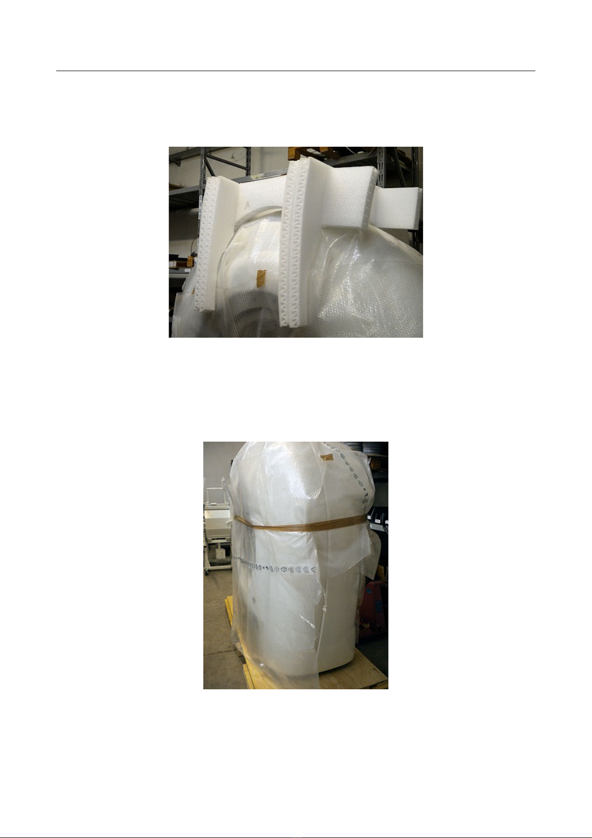
2. Remove all the packing materials and store the component boxes in a safe place. Carefully inspect
all components inside the crate for signs of any shipping or internal damage.
Do not attempt set-up, installation, or operation of any damaged system.
3. From the base of the crate remove the two lifting tubular bars, the two flat junctions bar and the
four “T” shaped lifting screws.
4. Remove the bubble wrap protection from the scanner.
1-2 NewTom 5G – Installation Manual
1 Unpacking and moving the equipment
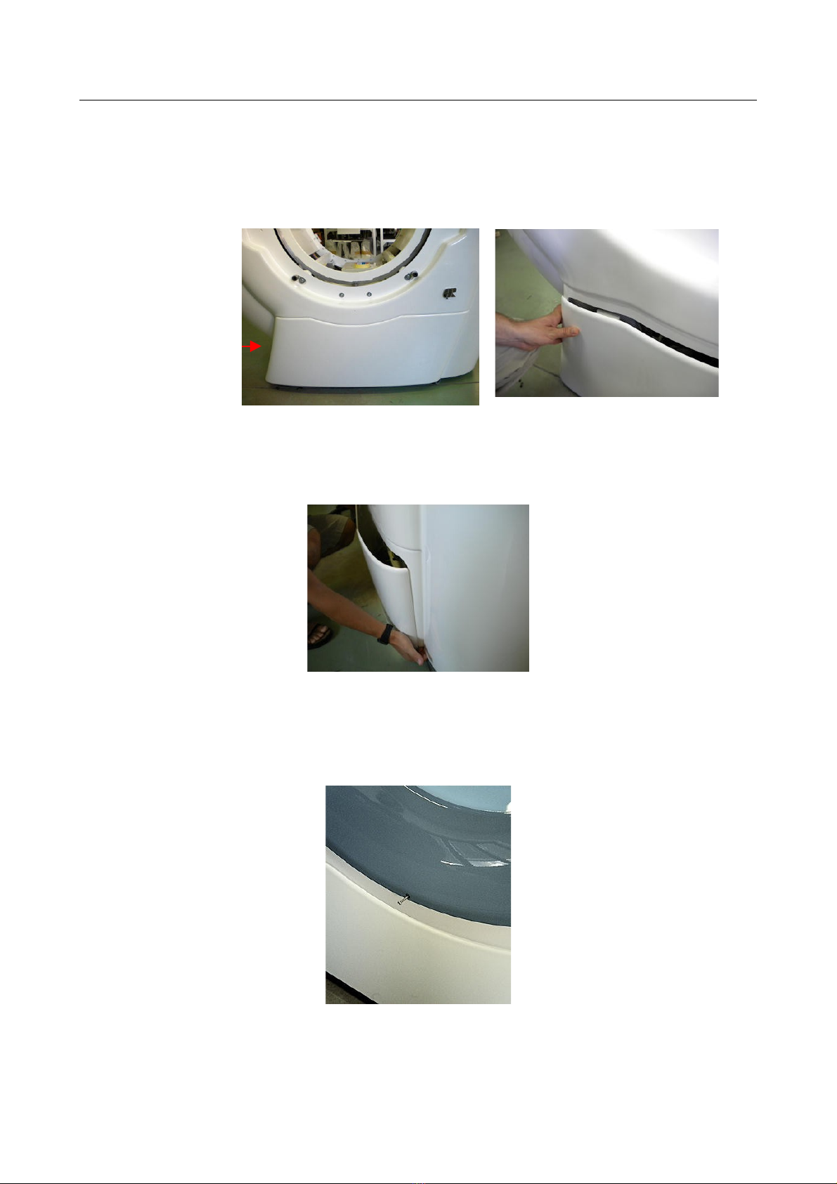
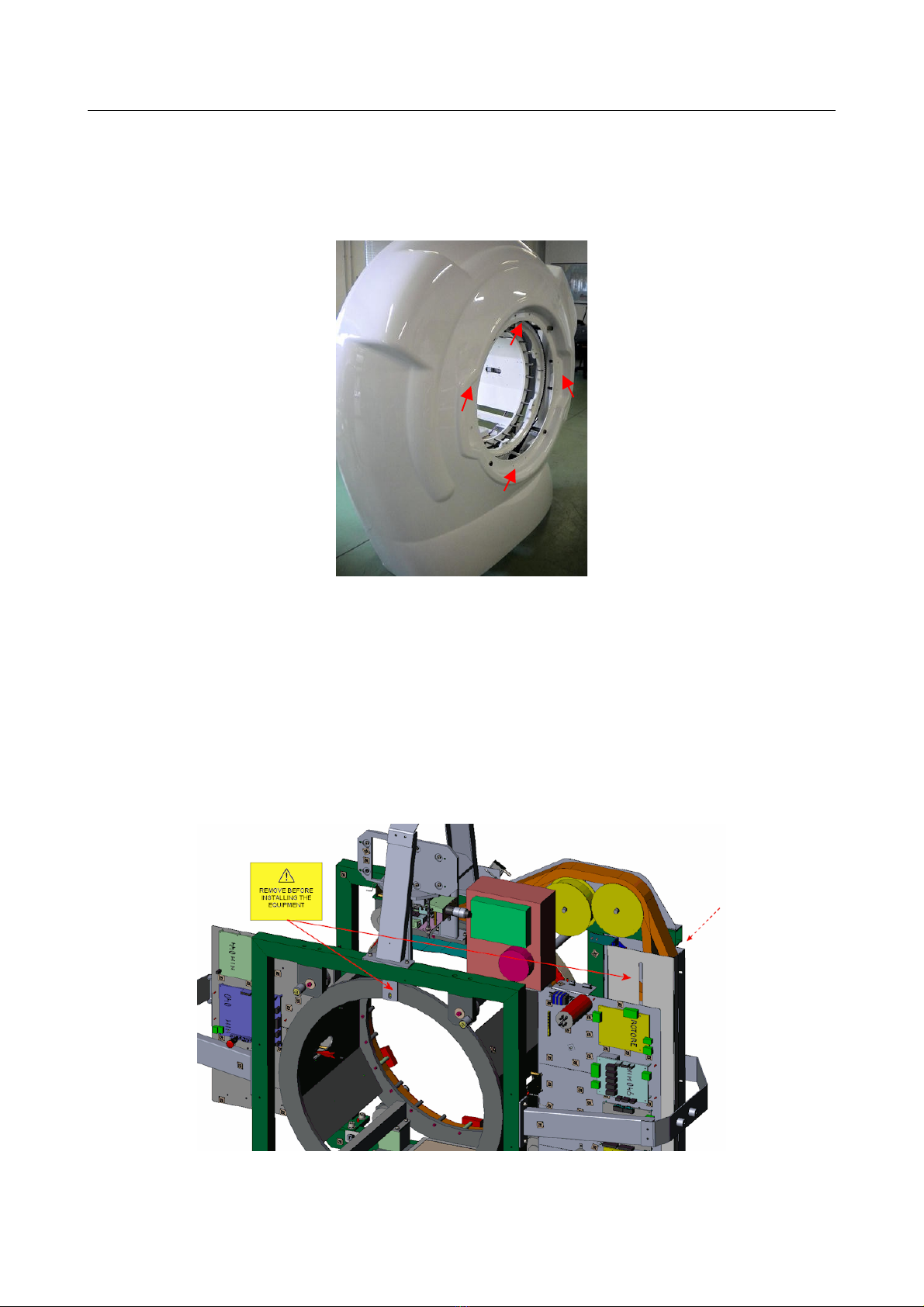
5. Removing the “Front Panel Thermoformed Carter” (97465006)
Unscrew the M4x20 hex socket screw located on the left side of the Front Panel Thermoformed
Carter.
Disengage the left side of the Front Panel Thermoformed Carter by sliding it down, therefore grab
the top side and pull it toward you until the right side unhooks from the Anterior Thermoformed
Carter.
6. Remove the anterior “Plastic Ring” (97465003)
Unscrew the M4x20 self-tapping screw located on the bottom side of the Plastic Ring.
Unhook the Plastic Ring from the 2 top inserts, then disconnect the control panels (C8 and C9
connectors) and the emergency buttons on both left and right side of the gantry.
NewTom 5G – Installation Manual 1-3
M4x20 hex
screw
1 Unpacking and moving the equipment
Then unhook the 2 bottom inserts.
Pay attention to do not damage the cables.
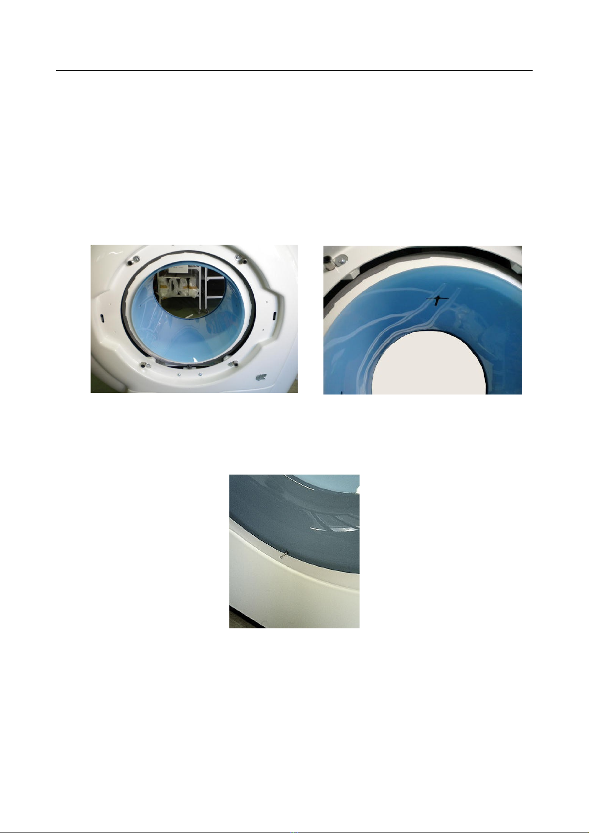
7. Removing the “Plastic Cylinder” (97465007)
Remove the Plastic Cylinder by holding its top side with the palm of the hand, and sliding it out of
the gantry.
Be carefully to do not scratch the external surface of the cylinder while sliding it out.
8. Removing the posterior “Plastic Ring” (97465003)
Unscrew the M4x20 self-tapping screw located on the bottom side of the Plastic Ring.
9. Unhook the Plastic Ring from the 4 back inserts (there are no cables connected to the posterior
ring).
1-4 NewTom 5G – Installation Manual

1 Unpacking and moving the equipment
10. Removing the “Anterior Thermoformed Carter” (97465004)
Unscrew the 8 M6x16 hex. socket screws and 8 M6x24 washers from the Anterior Thermoformed
Carter.
Pull back the control panels and emergency button cables through the dedicated holes on the
Anterior Thermoformed Carter (see following picture).
Slide out the Anterior Thermoformed Carter from the 4 spacers and store in a safe place.
NewTom 5G – Installation Manual 1-5
1 Unpacking and moving the equipment
11. Removing the “Posterior Thermoformed Carter” (97465005)
Unscrew the 8 M6x20 hex socket screws, 8 M6x24 washers and 8 M6x18 washers from the
Posterior Thermoformed Carter.
Slide out the Posterior Thermoformed Carter from the 4 spacers and store in a safe place.
12. Unscrew the M8x25 socket caps screw from the Block-chassis plate (99934481).
13. Remove the block-chassis plate by unscrewing the two M6x20 socket caps screws that hold the
plate to the main structure.
14. Unlock the counterweight of the cable chain by removing the M8x80 hex screw.
1-6 NewTom 5G – Installation Manual

1 Unpacking and moving the equipment
15. Unscrew 4 nuts from the bottom of the crate base, then remove the 4 M10x210 hex screws from the
4 wood spacer supports, located below the holes designed for the adjustment of the device feet.
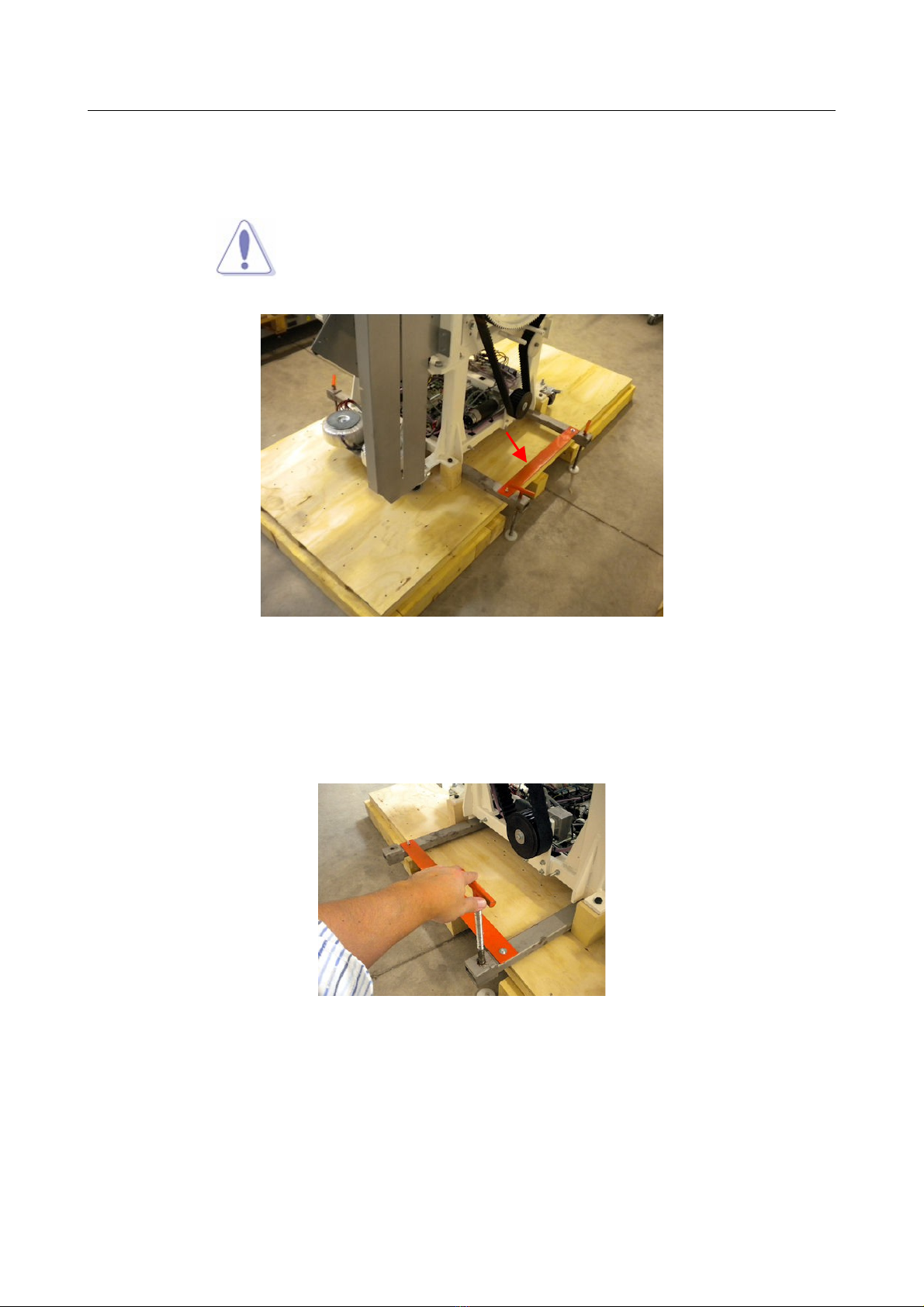
16. Place the two tubular lifting bars below the device base and verify they match with the by main
structure tubular.
The lifting bars include references for a correct positioning (verify they are not positioned below the
electronic plate).
WARNING:
It is very important that the lifting bars are correctly positioned on
both the right and left side in order to ensure the device to be
balanced during the lifting process.
NewTom 5G – Installation Manual 1-7
1 Unpacking and moving the equipment
17. Install the front and rear junction flat bar using 4 M5 screws provided with the equipment. These
bars connect the two lifting bar together, forming a rigid and solid frame.
WARNING:
It is very important to properly mount the two junction bars in
order to stabilize the device during the lifting process.
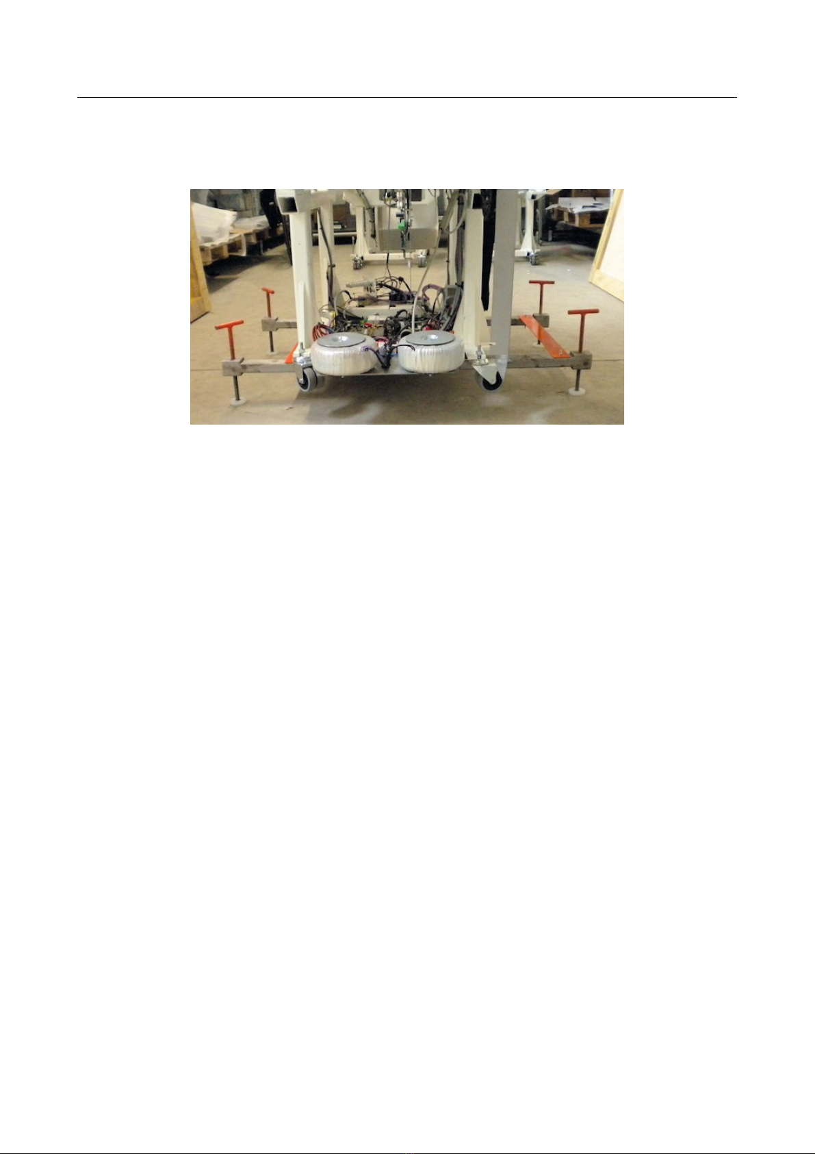
18. Mount the four ”T” shaped lifting screws on the lifting bars, and position the 4 plastic feet.
19. Slowly lift the device by equally screwing the four ”T” shaped lifting screws, until the wood spacer
supports can be removed.
Be careful to do not tilt too much the equipment during the lifting process.
1-8 NewTom 5G – Installation Manual
1 Unpacking and moving the equipment
20. Remove the base of the crate, paying attention to do not bang into the 4 lifting screws.
21. Slowly lower the device by equally unscrewing the 4 ”T” shaped lifting screws, until the it rest on the
wheels.
Be careful to do not tilt too much the equipment while lowering it.
22. Remove the ”T” shaped lifting screws, the plastic feet, the junction bars and the lifting tubular bars.
NewTom 5G – Installation Manual 1-9

1 Unpacking and moving the equipment
1.2 Moving the equipment
Once the machine rests on the wheels (without any cover mounted) it can be carefully moved to the final
position.
WARNING:
In case the device needs to travel through a ramp, move it down
sideway. Maximum admitted inclination is 10%.
1-10 NewTom 5G – Installation Manual

1 Unpacking and moving the equipment
In case the device needs to be lifted with the aid of a a crane, it is possible to roped it up using belt with 1000
Kg (2204 lb) capacity, secured to the front and rear side of the main structure as shown in the following
picture.
Alternatively four M12 threaded holes are provided in order to mount 4 lifting rings (see following picture).
NewTom 5G – Installation Manual 1-11
1 Unpacking and moving the equipment
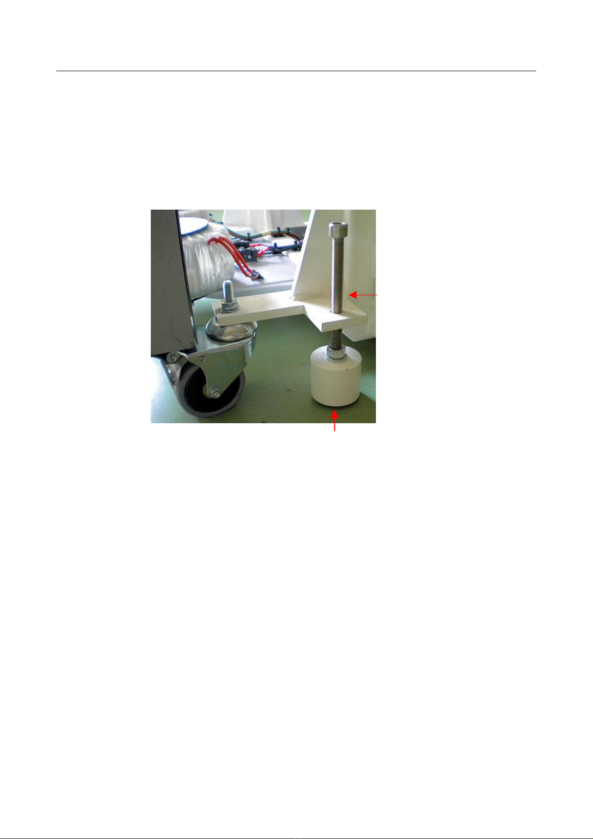
Once the device is in the final position the wheels must be replaced with the provided support feet.
Place the each foot below the corresponding M12x140 screws, then equally tighten each screw in order to lift
up the device, until the wheels are free and can be removed (see following picture).
Once all the wheels have been removed lower down the equipment by equally loosing each screw until the
two frontal screws responsible for the table coupling, matches with the table holes.
1. Patient table inspection and unpacking instructions
For unpacking, moving and preparing the patient table for the installation please refer to the provided
“Patient Ta le Installation Manual”.
1-12 NewTom 5G – Installation Manual
1 M12x140
hex screw
99934441 – SUPPORT FEET

2 Mounting and connecting the equipment
2 Mounting and connecting the equipment
2.1 Lasers setup
Please refer to the “Service Manual” document.
2.2 Mounting the equipment
1. Mounting the Posterior Thermoformed Carter (97465005)
Lean the “Posterior Thermoformed Carter” to the main structure, center it with the aid of the
mounted spacers and fix it using eight M6x20 socket caps screws, eight M6x24 washers and eight
M6x18 washers.
CAUTION:
Do not use the spacers designed for centering the posterior
carter, to lift or move the device.
Remove the surface protection film from the “Posterior Thermoformed Carter”.
NewTom 5G – Installation Manual 2-1

2 Mounting and connecting the equipment
2. Mount the Input Main Switch plate fixing it with four M4x20 socket caps screws and four M4 washers
(see next picture).
3. Mounting the “Anterior Thermoformed Carter” (97465004)
Run the control panels and emergency button cables through the dedicated holes on the Anterior
Thermoformed Carter (see following picture).
2-2 NewTom 5G – Installation Manual

2 Mounting and connecting the equipment
Lean the Anterior Thermoformed Carter to the main structure, center it with the aid of the mounted
spacers and fix it using eight M6x16 socket caps screws and eight M6x24 washers.
CAUTION:
Do not use the spacers designed for centering the posterior
carter, to lift or move the device.
Remove the surface protection film from the “Anterior Thermoformed Carter”.
4. Mounting the “Posterior Plastic Ring” (97465003).
Lean the Plastic Ring to the 4 Bollhoff rubber inserts and press it.
Tight the M4x20 self-tapping screw located on the bottom side of the Plastic Ring
NewTom 5G – Installation Manual 2-3
2 Mounting and connecting the equipment
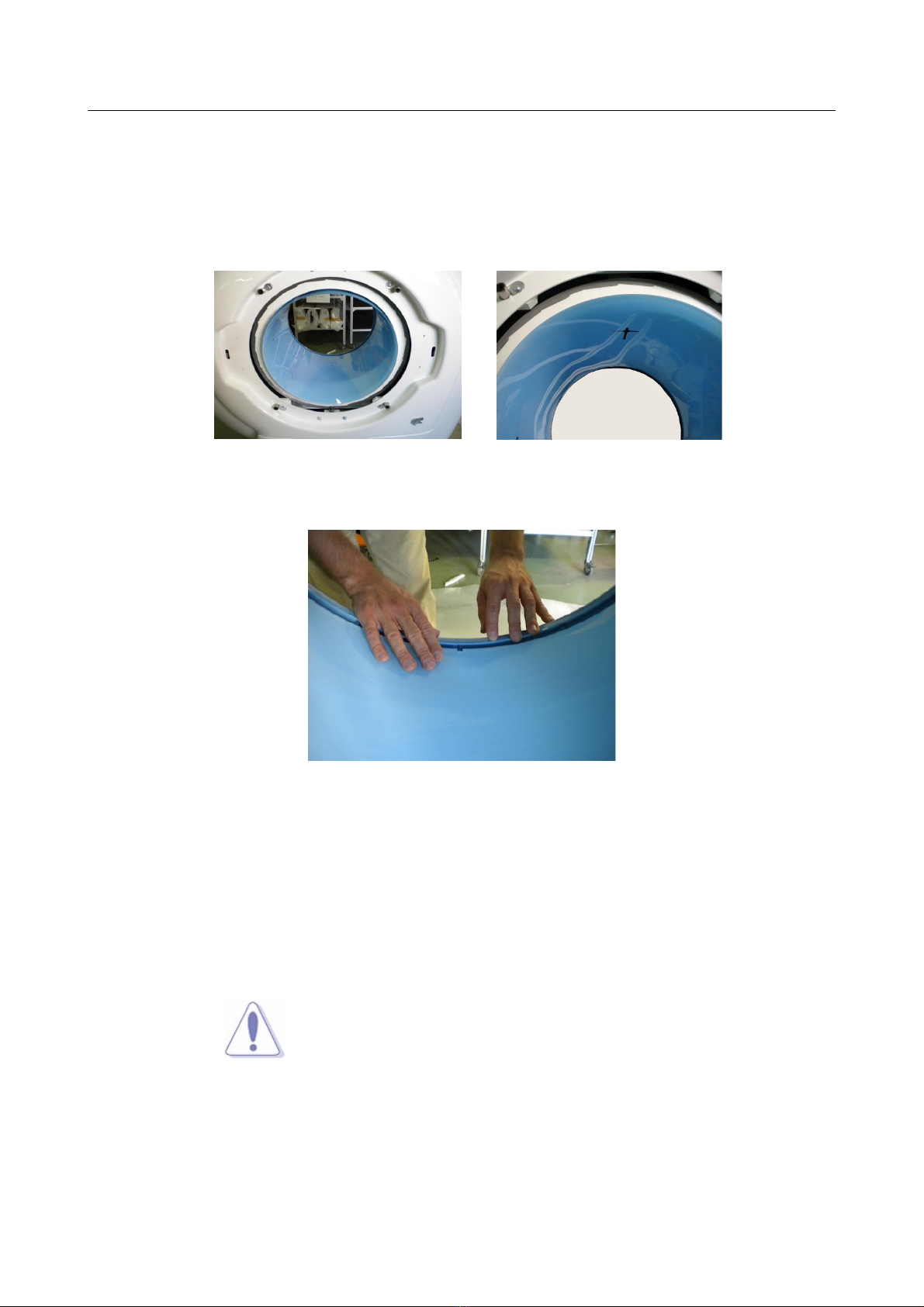
5. Mounting the “Plastic Cylinder” (97465007).
Insert the Plastic Cylinder inside the gantry paying attention to do not reverse the frontal side with
the rear side (the laser cross painted on the top of the cylinder has to be direct toward the front of
the device. See following picture)
Center the Plastic Cylinder by matching its notches with the clutches of the plastic ring.
6. Mounting the “Anterior Plastic Ring” (97465003).
Lean the Anterior Plastic Ring to the two bottom Bollhoff inserts and connect the two control panels
(connector C8 and C9) and the emergency buttons.
Lean the Anterior Plastic Ring to the two top Bollhoff inserts then press the entire ring until it's
engaged.
CAUTION:
Pay attention to do not reverse the control panel connectors
(specific label are stuck on each connector).
Once the device is turned on, “Power O ” led on the control
panels must be lighted with green color.
In case “Power O ” led is yellow, connection is reversed.
7.
2-4 NewTom 5G – Installation Manual

2 Mounting and connecting the equipment
8. Fix the “Anterior Plastic Ring” by tightening the M4x20 self-tapping screw located on the bottom side.
9. Coupling the patient table
Couple the patient table to the scanner by matching the two provided screws mounted on the
front side of the scanner, with the two holes located on the rear bracket of the patient table, and
fixing it with the provided nuts and washers.
Connect connectors C4F, C5F, C6M, C7F located on the front side of the scanner with the
corresponding C4M, C5M, C6F, C7M connector of the patient table.
Tie the cables to the provided cable tie mount and verify they won't interfere with the rotating
frame of the scanner.
NewTom 5G – Installation Manual 2-5
Left control panel connector Right control panel connector
Table of contents
Other NewTom Medical Equipment manuals


Popular Medical Equipment manuals by other brands


Getinge
Getinge Arjohuntleigh Nimbus 3 Professional Instructions for use

Mettler Electronics
Mettler Electronics Sonicator 730 Maintenance manual

Pressalit Care
Pressalit Care R1100 Mounting instruction

Denas MS
Denas MS DENAS-T operating manual

bort medical
bort medical ActiveColor quick guide

AccuVein
AccuVein AV400 user manual


