NewTom GiANO User manual

NewTom GiANO - TECHNICAL MANUAL –Rev 4
Service Manual Rev 4
March 01 , 2019
Cod. 97050631

NewTom GiANO - TECHNICAL MANUAL –Rev 4
NOTE
This document is provided for the own use of the operator of the equipment.
CEFLA s.c. reserves the right to change the contents of this manual without notice.
This document may not, in whole or in part, be modified, copied, reproduced, distributed, translated, stored on
magnetic or optical media and published, over networks, electronic bulletin boards, web sites or other on-line services,
without the express written permission of CEFLA s.c.
The original version of this manual has been written in English language.
NEWTOM™ GiANO is a commercial trademark of CEFLA s.c.
All other products and brand names are registered trademarks or trademarks of their respective companies.
MANUFACTURER’S NOTICE ABOUT MEDICAL DEVICES
The medical device described in this manual, composed by Scan Unit (gantry), display and computation unit (Main
Workstation) as delivered and configured by the manufacturing and servicing personnel, is a medical radiological device
subject to the safety requirement stated by both international standards and local regulation.
Any change, modification, update on either hardware
1
, or software
2
, on the device and operating settings as released
form factory and as installed (and in any case different from what has been specified on the device's attached
documentation), can cause the partial or total device impossibility to operate as expected. Moreover its safety features
can be changed with increased hazard for the patient, operator and surrounding environment.
So, in case that the final user need to modify or change any of the above specified items, he/she has to be allowed in
written by CEFLA s.c.
Any act outside of what has been stipulated on this notice will cancel the warranty. Moreover the person and/or
organization will be liable for any damage and/or incident and/or deterioration in the state of health of a patient, user
or other person and/or the surrounding environment.
1
Adding a memory expansion, a new board on the connection bus, a new printer, the replacement of the graphic adapter is a significant
change.
2
Including the Operating System an applications already installed when the device has been delivered and/or installed. Operating
system automatic updates, changes on the network connection parameters, modification and/or addition and/or removal of hardware
interface software (device driver) and/or system services (example: file sharing) and/or applications, constitute a significant change.

NewTom GiANO - TECHNICAL MANUAL –Rev 4
1 -About this manual........................................................................................................................................................ 1-8
1.1 Structure................................................................................................................................................................ 1-8
1.2 Attached documents............................................................................................................................................. 1-9
1.3 Conventions used in this manual ......................................................................................................................... 1-9
2 -Safety information...................................................................................................................................................... 2-10
2.1 General safety ..................................................................................................................................................... 2-10
2.2 Electrical safety ................................................................................................................................................... 2-11
2.3 Safety inspection guide....................................................................................................................................... 2-12
2.4 Handling Electrostatic Discharge-Sensitive Devices.......................................................................................... 2-13
2.5 Grounding Requirements ................................................................................................................................... 2-14
2.6 X-Ray Warning..................................................................................................................................................... 2-14
2.7 Laser warning ...................................................................................................................................................... 2-14
3 -General information .................................................................................................................................................. 3-15
3.1 Label symbols ...................................................................................................................................................... 3-15
4 -Installation.................................................................................................................................................................... 4-16
4.1 Unpacking............................................................................................................................................................ 4-16
4.2 Transportation with trolley................................................................................................................................. 4-18
4.3 Transportation with handles (COD 96600540).................................................................................................. 4-19
4.4 Wall mounting..................................................................................................................................................... 4-19
4.5 Mounting on stative base ................................................................................................................................... 4-21
4.6 Removing bolts used for shipment .................................................................................................................... 4-22
4.7 Patient arm installation....................................................................................................................................... 4-23
4.8 Electrical connections on PFC board.................................................................................................................. 4-27
4.9 Connecting the Ethernet cables and remote x-Ray button .............................................................................. 4-29
4.10 CEPH arm installation.......................................................................................................................................... 4-31
4.11 Covers mounting ................................................................................................................................................. 4-35
4.11.1 Kinematic arm covers ................................................................................................................................ 4-36
4.11.2 Longherone covers..................................................................................................................................... 4-36
4.11.3 Sensors rotating arm covers...................................................................................................................... 4-39

NewTom GiANO - TECHNICAL MANUAL –Rev 4
4.11.4 Final touches .............................................................................................................................................. 4-40
4.11.5 CBCT Panel installation .............................................................................................................................. 4-41
5 -Main workstation setup (only for 3D Full) ............................................................................................................... 5-42
5.1 Preliminary Operations....................................................................................................................................... 5-42
5.2 Operating system settings .................................................................................................................................. 5-42
5.2.1 Graphic card installation ................................................................................................................................ 5-43
5.2.2 User account settings..................................................................................................................................... 5-45
5.2.3 Disabling automatic updates.......................................................................................................................... 5-46
5.2.4 Device installation settings ............................................................................................................................ 5-48
5.2.5 Windows defender settings ........................................................................................................................... 5-50
5.2.6 Power Options settings .................................................................................................................................. 5-53
5.2.7 Disabling the “Fast start up” option .............................................................................................................. 5-54
5.2.8 Disabling screen saver.................................................................................................................................... 5-55
5.2.9 Extend single process memory limit (only for Operating System with 32 bit) ......................................... 5-57
5.3 NNT software installation ................................................................................................................................... 5-58
5.4 2D Connection between PC and GiANO ............................................................................................................ 5-60
5.4.1 Setting up connection for communication and 2D images.......................................................................... 5-60
5.4.2 Establish the 2D connection (PC <–> scanner) ............................................................................................. 5-64
5.4.3 Changing the IP address of scanner .............................................................................................................. 5-65
5.5 3D Connection between PC and Giano (for 3D-FULL ONLY)............................................................................. 5-67
5.5.1 Flat Panel (CBCT) driver installation .............................................................................................................. 5-67
5.5.2 “Intel Gigabit CT Desktop Adapter” network card installation .................................................................... 5-68
5.5.3 Install Paxscan L09 driver ............................................................................................................................... 5-69
5.5.4 Preparing the 3D connection (Intel Desktop Adapter <-> 3D Flat Panel).................................................... 5-73
5.5.5 Configuring 3D Panel driver directory and establish 3D connection........................................................... 5-74
6 -GiANO CALIBRATION................................................................................................................................................. 6-75
6.1 Factory backup Folder ........................................................................................................................................ 6-75
6.2 2D Calibration...................................................................................................................................................... 6-75
6.2.1 Calibration kit.................................................................................................................................................. 6-75
6.2.2 Verifying device configuration ....................................................................................................................... 6-76

NewTom GiANO - TECHNICAL MANUAL –Rev 4
6.2.3 Column calibration ......................................................................................................................................... 6-78
6.2.4 PAN x-ray alignment....................................................................................................................................... 6-81
6.2.5 PAN sensor calibration ................................................................................................................................... 6-93
6.2.6 PAN mechanical centering ............................................................................................................................. 6-95
6.2.7 Laser test.......................................................................................................................................................6-102
6.2.8 CEPH x-ray alignment ................................................................................................................................... 6-104
6.2.9 Ceph sensor calibration................................................................................................................................ 6-111
6.2.10 CEPH mechanical centering.....................................................................................................................6-113
6.2.11 Headrest calibration ................................................................................................................................6-115
6.2.12 Nasion calibration .................................................................................................................................... 6-117
6.2.13 Auricolar guides adjustment ...................................................................................................................6-121
6.2.14 Calibration backup ...................................................................................................................................6-122
6.2.15 Calibration restore ...................................................................................................................................6-124
6.2.16 Calibration Report PDF ............................................................................................................................6-126
6.3 3D Calibration....................................................................................................................................................6-127
6.3.1 3D Calibration Kit..........................................................................................................................................6-127
6.3.2 Enabling the service level.............................................................................................................................6-127
6.3.3 Beam Limiter Test.........................................................................................................................................6-128
6.3.4 Daily Check....................................................................................................................................................6-131
6.3.5 Mattarellum Acquisition...............................................................................................................................6-133
6.3.6 Verifying 3D calibration................................................................................................................................6-137
6.3.7 Exporting 3D calibration data ......................................................................................................................6-141
6.3.8 Importing 3D calibration data......................................................................................................................6-141
7 -Boards layout ............................................................................................................................................................ 7-142
7.1 Circuit boards description.................................................................................................................................7-142
7.2 General block schematic...................................................................................................................................7-143
7.3 Mainboard (97661026).....................................................................................................................................7-144
7.3.1 Connector list................................................................................................................................................7-146
7.3.2 Diagnostic leds..............................................................................................................................................7-147
7.3.3 Dip switches..................................................................................................................................................7-149

NewTom GiANO - TECHNICAL MANUAL –Rev 4
7.3.4 Memory Battery ........................................................................................................................................... 7-149
7.4 Power Board (97661113)..................................................................................................................................7-150
7.4.1 Connector list................................................................................................................................................7-152
7.4.2 Fuses..............................................................................................................................................................7-152
7.4.3 DIAGNOSTIC LEDs .........................................................................................................................................7-153
7.4.4 Dip switches..................................................................................................................................................7-153
7.5 Converter (97661114) ......................................................................................................................................7-154
7.5.1 Connectors list ..............................................................................................................................................7-156
7.5.2 Diagnostic led................................................................................................................................................7-157
7.5.3 Dip switches..................................................................................................................................................7-157
7.5.4 Fuses..............................................................................................................................................................7-157
7.6 Consolle (97661110).........................................................................................................................................7-158
7.6.1 Connectors list ..............................................................................................................................................7-160
7.6.2 Diagnostic led................................................................................................................................................7-160
7.6.3 Dip switches..................................................................................................................................................7-160
7.7 Column inverter board (97661076) .................................................................................................................7-161
7.7.1 Connectors list ..............................................................................................................................................7-163
7.7.2 Diagnostic LEDs.............................................................................................................................................7-163
7.7.3 Dip switches..................................................................................................................................................7-163
7.8 Stepper “GSENS” configuration (Rotating PAN/CBCT sensor support) (97661112).....................................7-164
7.8.1 Connector list................................................................................................................................................7-166
7.8.2 Diagnostic LEDs.............................................................................................................................................7-166
7.8.3 Dip switches..................................................................................................................................................7-166
7.9 Stepper “MSENS” configuration (Motorized chin support) (97661112).......................................................7-167
7.9.1 CONNECTOR LIST.......................................................................................................................................... 7-169
7.9.2 Diagnostic LEDs.............................................................................................................................................7-169
7.9.3 Dip switches..................................................................................................................................................7-169
7.10 Stepper “CSENS” configuration (CEPH arm ear guides and nasion control) (97661112 ) ...........................7-170
7.10.1 Connector list ...........................................................................................................................................7-172
7.10.2 Diagnostic LEDs ........................................................................................................................................7-172

NewTom GiANO - TECHNICAL MANUAL –Rev 4
7.10.3 Dip switches ............................................................................................................................................. 7-172
7.11 Monoblock (97750183) ....................................................................................................................................7-173
7.11.1 Connector list ...........................................................................................................................................7-174
7.12 X-Ray Command (97661136)............................................................................................................................7-174
7.12.1 Diagnostic LEDs ........................................................................................................................................7-174
7.12.2 Dip switches ............................................................................................................................................. 7-174
7.12.3 CONNECTOR LIST ..................................................................................................................................... 7-174
8 -Troubleshooting ........................................................................................................................................................ 8-175
8.1 NNT Log error viewer (only from NNT 8.0)..................................................................................................... 8-176
8.2 Maintenance procedures .................................................................................................................................8-176
8.3 Error 8.1/8.2/8.7 (Mobile section of turret unit) ............................................................................................8-178
9 -Extranet site ............................................................................................................................................................... 9-180

NewTom GiANO - TECHNICAL MANUAL –Rev 4
1 - About this manual
This manual has been prepared to provide information and instructions regarding the installation, use, maintenance,
and troubleshooting of the "NewTom GiANO" device series.
This manual is intended for trained personnel recognized by the manufacturer of the "NewTom GiANO" model device.
Prior to operating or servicing this device, this manual must be read and understood.
Keep this and other associated manuals for future reference and for new operators or qualified service personnel.
1.1 Structure
The manual has been written in a narrative form supplemented with schematics and drawings for clarification. It is
divided into chapters as follows:
The “About this manual” chapter provides general information about the manual.
The “Safety Information” chapter provides guidelines, and safety information required servicing the machine.
The “General Information” chapter includes information about the labels used for the shipment and located on
the equipment, and an overview of the service window on the software.
The “Installation”chapter provides instructions regarding the installation of the equipment.
The “System requirements”chapter includes requirements for the computer to be used with the scanner
and/or software.
The “Main Workstation setup”chapter contains information regarding the preparation of the console
workstation.
The “GiANO Calibration”chapter describes the procedure for a complete calibration of the system.
The “Boards layout”chapter provides information regarding the electronic boards of the device.
The “Troubleshooting”chapter provides guidelines to solve problem or failure that could happen.

NewTom GiANO - TECHNICAL MANUAL –Rev 4
1.2 Attached documents
The following documents is an attachment of this manual:
-“OPT-Hybrid Error Guide” code 97050604.
1.3 Conventions used in this manual
Text format
Example
Meaning
Bold Italic
File
Open
Menu or toolbar item
Italic
Patient File
Window Title
Bold Underlined
“Apply”
Button Command
<text>
<Demonstration template>
Typed text
CAPITAL LETTER
ENTER
keyboard command
To make sure that you perform certain tasks properly, take note of the following symbols used throughout this manual:
DANGER / WARNING: Information to prevent injury to yourself
when trying to complete a task.
CAUTION: Information to prevent damage to the components
when trying to complete a task.
IMPORTANT: Instructions that you MUST follow to complete a
task.
NOTE: Tips and additional information to help you complete a
task.

NewTom GiANO - TECHNICAL MANUAL –Rev 4
2 - Safety information
The following section contains the safety information that you need to be familiar with before servicing a NewTom
GiANO. Additional information are included inside the User Manual under the “Safety warnings” chapter.
2.1 General safety
Follow these rules to ensure general safety:
Observe good housekeeping in the area of the machines during and after maintenance.
When lifting any heavy object:
1. Ensure you can stand safely without slipping.
2. Distribute the weight of the object equally between your feet.
3. Use a slow lifting force. Never move suddenly or twist when you attempt to lift.
4. Lift by standing or by pushing up with your leg muscles; this action removes the strain from the muscles in
your back. Do not attempt to lift any objects that you think are too heavy for you.
Do not perform any action that causes hazards to the customer, or that makes the equipment unsafe.
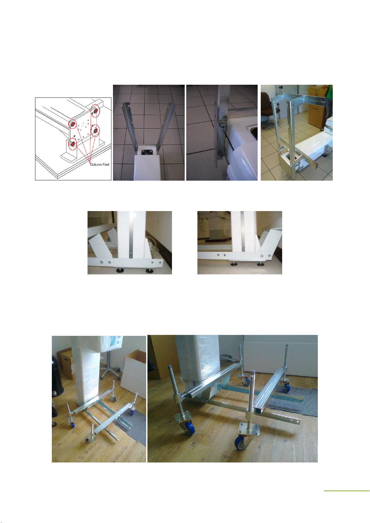
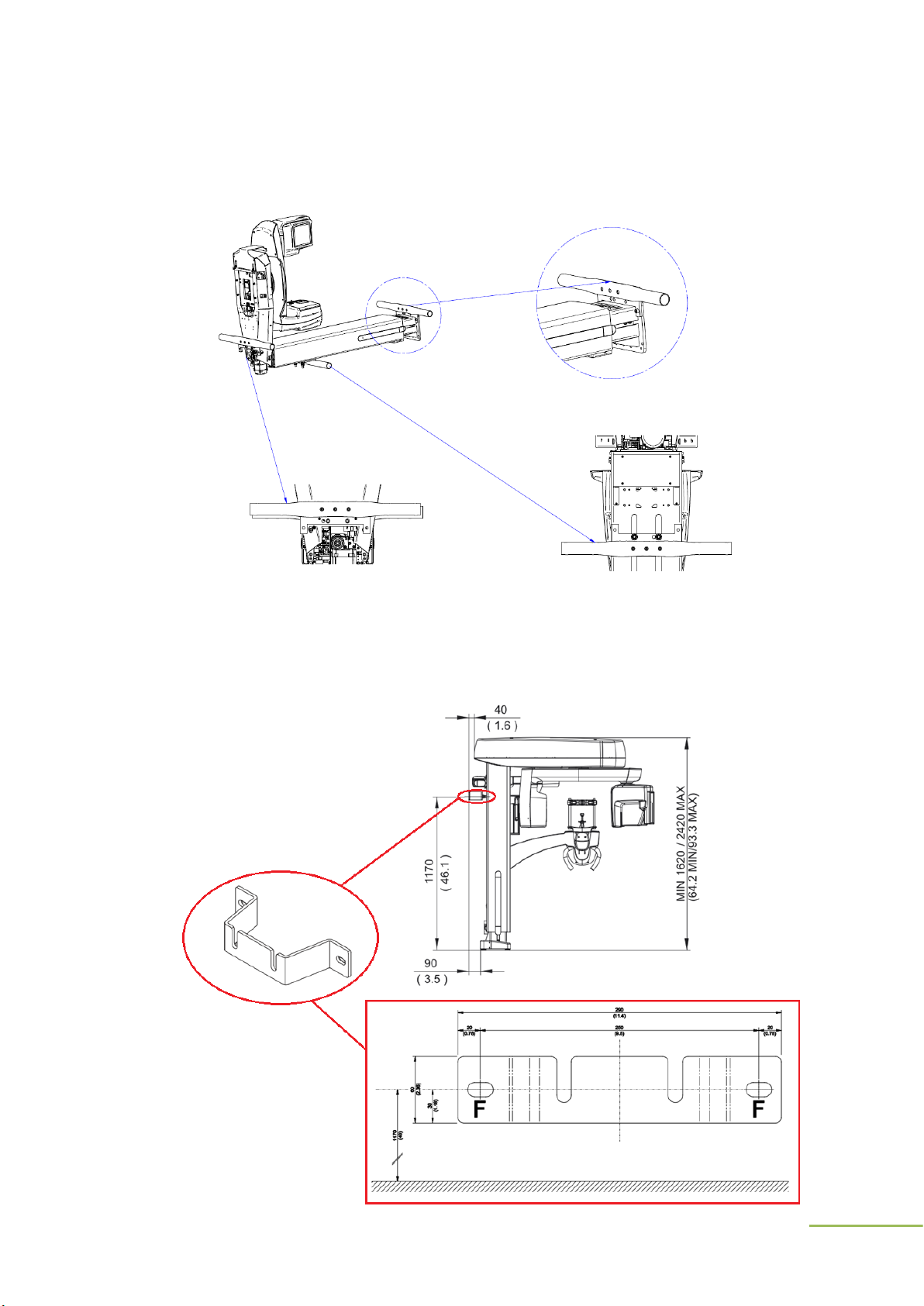
Perform an installation that achieve a optimal use. Care to
obstacles do motorized motion,
mechanical damage of connecting cable,
patient-operator visibility,
device accessibility for maintenance and cleaning, etc...
Before you start the machine, ensure that other service representatives and the customer's personnel are not
in a hazardous position.
Place removed covers and other parts in a safe place, away from all personnel, while you are servicing the
machine.
Keep your tool case away from walk areas so that other people will not trip over it.
Do not wear loose clothing that can be trapped in the moving parts of a machine. Ensure that your sleeves are
fastened or rolled up above your elbows. If your hair is long, fasten it.
Insert the ends of your necktie or scarf inside clothing or fasten it with a nonconductive clip.
Do not wear jewelry, chains, metal-frame eyeglasses, or metal fasteners for your clothing.
Wear safety glasses when you are: hammering, drilling soldering, cutting wire, using solvents, or working in
any other conditions that might be hazardous to your eyes.
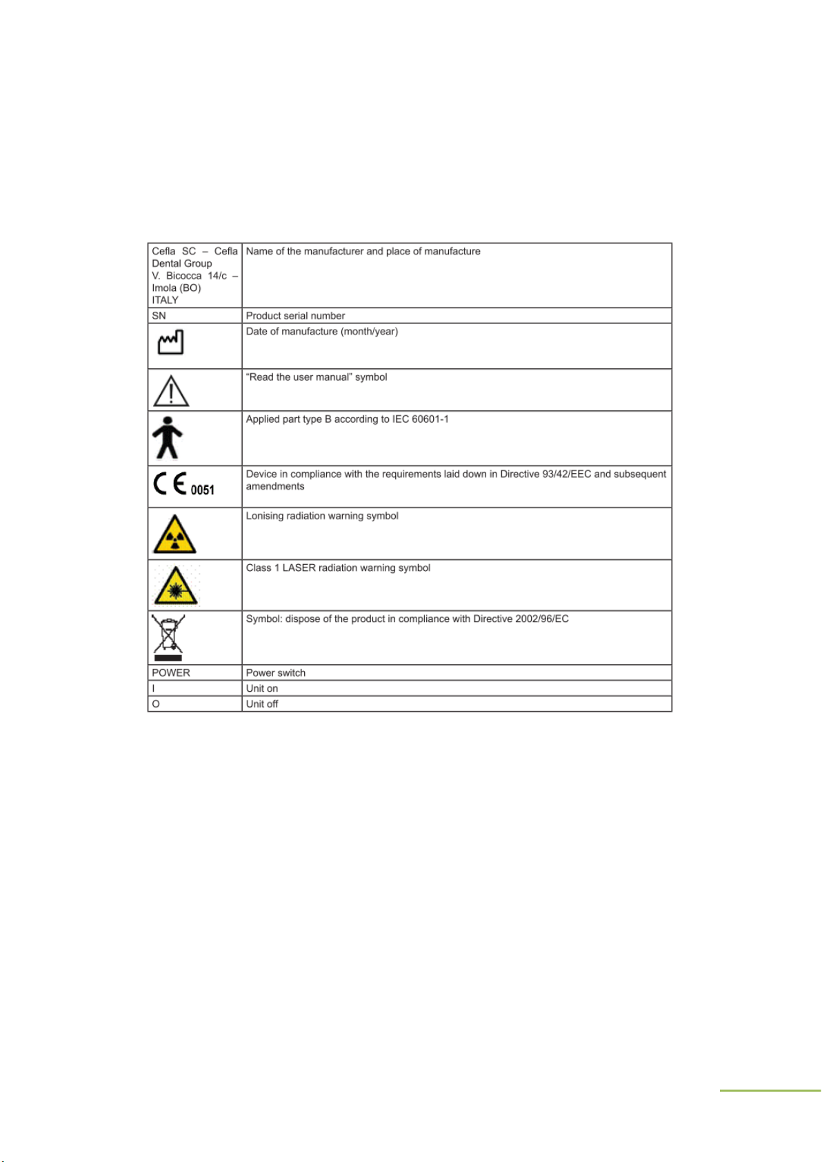
Follow all cautions and instructions marked on the equipment.
Do not under any circumstances, remove any Caution, Warning or any other descriptive labels from the device
until the conditions warranting the label are eliminated.
To avoid fire or explosion, do not operate this device in an explosive environment or near flammable
anesthetics.
After service, reinstall all safety shields, guards, labels, and ground wires. Replace any safety device that is
worn or defective.
Reinstall all covers correctly before returning the machine to the customer.
Do not under any circumstances make mechanical or electrical modifications to the equipment. Manufacturer
is not responsible for regulatory compliance of a modified product.
Connect to the device only computers, computer peripherals and cables in compliance to the manufacturer
specifications

NewTom GiANO - TECHNICAL MANUAL –Rev 4
CAUTION: There are no user serviceable parts inside the unit.
Broken and/or defective parts must be returned to manufacturer
and replaced with spare part approved by the manufacturer or
distributor.
CAUTION: For continued protection against risk of fire, replace
only with same type and rating of fuse.
2.2 Electrical safety
Observe the following rules when working on electrical equipment.
WARNING: The NewTom GiANO is an equipment, containing high
voltage devices and must be opened only by qualified personnel,
authorized by CEFLA s.c.
WARNING: Use only approved tools and test equipment. Some
hand tools have handles covered with a soft material that does not
insulate you when working with live electrical currents.
WARNING: Metal objects are good electrical conductors.
Find the room emergency power-off (EPO) switch, disconnecting switch, or electrical outlet. If an electrical
accident occurs, you can then operate the switch or unplug the power cord quickly (if applied).
Do not work alone under hazardous conditions or near equipment that has hazardous voltages.
Disconnect all power before:
–Performing a mechanical inspection
–Working near power supplies
–Removing or installing main units
Before you start working on the machine, unplug the power cord. If you cannot unplug it, ask the customer to
power-off the wall box that supplies power to the machine and to lock the wall box in the off position.
If you need to work on an exposed electrical circuit, observe the following precautions:
-Ensure that another person, familiar with the power-off controls, is near you.
-
WARNING: Another person must be there to switch off the power,
if necessary.

NewTom GiANO - TECHNICAL MANUAL –Rev 4
-Use only one hand when working with powered-on electrical equipment; keep the other hand in
your pocket or behind your back.
NOTE: There must be a complete circuit to cause electrical
shock. By observing the above rule, you may prevent a current
from passing through your body.
-When using testers, set the controls correctly and use the approved probe leads and accessories
for that tester.
-Stand on suitable rubber mats (obtained locally, if necessary) to insulate you from grounds such
as metal floor strips and machine frames.
Regularly inspect and maintain your electrical hand tools for safe operational condition.
Never push objects of any kind through openings in the equipment. Dangerous voltages may be present.
Conductive foreign objects could produce a short circuit that could cause fire, electric shock, or damage to
your equipment.
Do not use worn or broken tools and testers.
Never assume that power has been disconnected from a circuit. First, check that it has been powered-off.
Always look carefully for possible hazards in your work area. Examples of these hazards are moist floors, no-
grounded power extension cables, power surges, and missing safety grounds.
Do not use household extension cords to supply the console workstation or the equipement.
Do not touch live electrical circuits with the reflective surface of a plastic dental mirror. The surface is
conductive; such touching can cause personal injury and machine damage.
To avoid electrical shock hazard, do not remove covers or panels when power is supplied to the device.
Do not under any circumstances remove the ground wire from any power plug.
Do not service the following parts with the power on when they are removed from their normal operating
places in a machine:
X-Ray source
X-Ray image intensifier
All the electronic boards
If an electrical accident occurs:
Use Caution: do not become a victim yourself.
Switch Off power.
Send another person to get medical aid.
Never connect to the system any other parts or accessories not specified from the manufacturer.
Install the equipment in a way that an optimal usage can be made by the operator. (Easy cleaning, servicing
and patient positioning).
2.3 Safety inspection guide
The intent of this inspection guide is to assist you in identifying potentially unsafe conditions of the device.
When inspecting a machine good judgment should be used to identify potential safety hazards.
If any unsafe conditions are present, you must determine how serious the apparent hazard could be and whether you
can continue without first correcting the problem.

NewTom GiANO - TECHNICAL MANUAL –Rev 4
Consider these conditions and the safety hazards they present:
Electrical hazards, especially primary power (primary voltage on the frame can cause serious or fatal electrical
shock).
Explosive hazards, such as a damaged or bulging capacitor
Mechanical hazards, such as loose or missing hardware
Checklist:
1. Check exterior covers for damage (loose, broken, or sharp edges).
2. Power-off the machine. Disconnect the power cord in case of detachable cable or power-off the wall box.
3. Check the power cord for:
a) A third-wire ground connector in good condition.
b) The power cord should be the appropriate type.
c) Insulation must not be frayed or worn.
4. Remove the cover.
5. Check for any obvious alterations. Use good judgment as to the safety of any alterations.
6. Check inside the unit for any obvious unsafe conditions, such as metal filings, contamination, water or other
liquids, or signs of fire or smoke damage.
7. Check for worn, frayed, or pinched cables.
8. Check for loosen or missing bolts.
2.4 Handling Electrostatic Discharge-Sensitive Devices
Any boards containing transistors or integrated circuits (ICs) should be considered sensitive to electrostatic discharge
(ESD). ESD damage can occur when there is a difference in charge between objects. Protect against ESD damage by
equalizing the charge so that the machine, the part, the work mat, and the person handling the part are all at the same
charge.
NOTES:
1) Use product-specific ESD procedures when they exceed the
requirements noted here.
2) Make sure that the ESD protective devices you use have been
certified (ISO 9000) as fully effective.
When handling ESD-sensitive parts:
Keep the parts in protective packages until they are inserted into the product.
Avoid contact with other people.
Wear a grounded wrist strap against your skin to eliminate static on your body.
Prevent the part from touching your clothing. Most clothing is insulate and retains a charge even when you are
wearing a wrist strap.
Use the black side of a grounded work mat to provide a static-free work surface. The mat is especially useful
when handling ESD-sensitive devices.
Select a grounding system to provide protection that meets the specific service requirement.
NOTE: The use of a grounding system is desirable but not
required to protect against ESD damage.

NewTom GiANO - TECHNICAL MANUAL –Rev 4
2.5 Grounding Requirements
Electrical grounding of the machine and computer is required for operator safety and correct system function. A
certified electrician can verify proper grounding of the electrical outlet.
2.6 X-Ray Warning
This equipment is a radiological device that can expose the personnel to the risk resulting from ionizing radiation. It
must be used in compliance with safety regulations, required by current radioprotection regulations in accordance with
local laws.
WARNING:The use of controls, adjustments, or the performance
of procedures other than those specified herein may result in
hazardous radiation exposure.
WARNING:In the NewTom VG an X-Ray source is present. Each
action, which causes the switching on of the NewTom 5G, must
be performed by qualified personnel, trained on the dangers and
risks connected with X-Rays for people.
Before switching on the NewTom VG, verify that the radiation
protection regulations for environment, people and operators
safety are respected.
2.7 Laser warning
The device is equipped with multiple positioning lasers. The beam is emitted from the front cover aperture and from
the consolle arm.
WARNING: Do not disassemble the optical instrument or
attempt to perform any internal servicing.
WARNING: Do not stare into the laser beams, do not view
directly with optical instruments, and avoid direct exposure to
the beam. The beams can cause permanent eye damage.
WARNING:. do not view directly the lasers; if necessary, use
appropriate protective glasses.
WARNING: The use of controls, adjustments, or the
performance of procedures other than those specified herein
may result in hazardous radiation exposure.

NewTom GiANO - TECHNICAL MANUAL –Rev 4
3 - General information
3.1 Label symbols
The following symbols may be found on the x-ray device.

NewTom GiANO - TECHNICAL MANUAL –Rev 4
4 - Installation
The installation of the X-ray unit should be performed only by a qualified technician in accordance with the instructions
of mechanical and electrical installation as defined below.
Check that the voltage indicated on the nameplate of the system corresponds to that of the local electrical supply.
4.1 Unpacking
The system, packed as it arrives, can be transported as close as possible to the installation building. Provide unpacking
outside of the practice by removing the cardboard packaging.
After cutting the straps for palletizing, remove all the boxes and place them in a safe location.
In order to unlock the device from the crate the two holding brackets, located at the base and at the top of the column,
must be removed (see below).

NewTom GiANO - TECHNICAL MANUAL –Rev 4
WARNING: when lifting the unit from the base be very careful to do not knock the column against the wooden support
as highlighted in the following diagram.

NewTom GiANO - TECHNICAL MANUAL –Rev 4
4.2 Transportation with trolley
Mount the feet (included in the supply box) at the base of the column, them mount the trolley to the base of the
scanner with the provided screws (refer to following pictures).
The crossbars with wheels near the post can be installed in two positions: in the front or back of the post.The figures
below illustrate the two positions of the holes and crossbar correctly installed.
Crossbar installed in the front Crossbar installed in the back
Stand up the scanner, then insert the caster wheels and loose each screw of the wheels until the scanner lift from the
floor. Be extremely carefull when moving the equipment.

NewTom GiANO - TECHNICAL MANUAL –Rev 4
4.3 Transportation with handles (COD 96600540)
As an alternative to the cart, for transporting the device can use the handles that, as shown in the figure, can be
fastened in three different positions.
4.4 Wall mounting
Device can be fixed on the wall by using the provided bracket (see following drawings). An installation scheme can be
found inside the supply box. It includes the dimension of the device with all the possible configurations, a 1:1 template
of the holding bracket and specific information related to power supply and connection of the scanner.

NewTom GiANO - TECHNICAL MANUAL –Rev 4
-Securely install the provided bracket on the wall (see above picture). Select a fastening system suitable for the
wall capable of withstanding a 220 kg tear force applied at each anchoring point.
NOTE: Use “FISHER GM 12” anchor bolts for concrete or solid brick wall.
As an alternative, FISHER chemical fixing are recommended consisting of:
Injection mortar (item FIP 16x85) –Threaded bar with bar and washer (item FIP 16M, 8x110). Chemical fixing
(Item FIS C 150)
-Important: remember to install the support feet at the base of the column before the machine is lifted vertically.
-Place the machine on the wall, resting on the legs and fasten it to the bracket not strictly with the provided
semi-spherical washers and nuts (see following picture)
Position
Code
Description
Quantity
2
99932130
PIN FOR WALL MOUNTING
2
3
52220045
M12 FLANGED NUT
4
52220011
UNI 5588 M12 MEDIUM NUT
5
53135024
M12 CONVEX WASHER
4
6
53135025
M12 CONCAVE WASHER
7
99932076
WALL BRACKET
1
-Remove the basket with its brackets;
-Check the leveling and if necessary adjust the feet;
-Complete the bracket fixing;
-Preferably, drill the floor in correspondence with the holes of service provided on the plate and fix the base to
the floor with 2 plugs.
This manual suits for next models
1
Table of contents
Other NewTom Medical Equipment manuals
Popular Medical Equipment manuals by other brands

Stryker
Stryker stair-pro 6250 Operation and maintenance guide

CaVstorm
CaVstorm Cavitation 3.0 MS-23T1 user manual

PARAMOUNT BED
PARAMOUNT BED KK-728E instruction manual

Orliman
Orliman Manutec M790 Use and maintenance instructions

Huntleigh
Huntleigh Hydroven 3 Instructions for use

ConMed
ConMed 7-796-18BX Instructions for use